Table of Contents
Advertisement
Quick Links
Advertisement
Table of Contents

Related Manuals for Datavideo VGB-4000

Summary of Contents for Datavideo VGB-4000
- Page 1 4K PRO PRESENTATION SYSTEM VGB-4000 Instruction Manual...
-
Page 2: Table Of Contents
5.3.1 C ................................. 36 ONNECTORS 6. HOW TO USE THE BUILT-IN DVK-400 HOLDOUT MASK FUNCTION OF THE VGB-4000 ..........37 7. HOW TO USE THE BUILT-IN DVK-400 IN VGB-4000 ...................... 40 8. HOW TO USE THE BUILT-IN NVS-33 IN VGB-4000......................40 9. - Page 3 SERVICE AND SUPPORT ..............................52 Disclaimer of Product & Services The information offered in this instruction manual is intended as a guide only. At all times, Datavideo Technologies will try to give correct, complete and suitable information. However, Datavideo Technologies cannot exclude that some information in this manual, from time to time, may not be correct or may be incomplete.
-
Page 4: Fcc Compliance Statement
7. This product should only be operated from the type of power source indicated on the marking label of the AC adapter. If you are not sure of the type of power available, consult your Datavideo dealer or your local power company. -
Page 5: Warranty
Warranty Standard Warranty Datavideo equipment are guaranteed against any manufacturing defects for one year from the date of purchase. The original purchase invoice or other documentary evidence should be supplied at the time of any request for repair under warranty. -
Page 6: Introduction
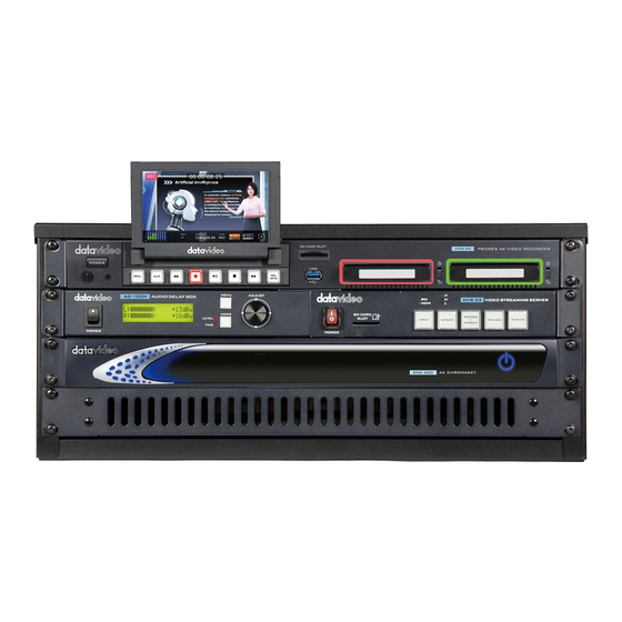
1. Introduction The VGB-4000 is a 4K Pro Presentation System and designed especially for the MOOC course video recording, TV station weather report and stock market analysis applications. The VGB-4000 system features as an all-in- one chassis system including chromakey, lumakey, audio delay and video recording, streaming functions to... -
Page 7: System Diagram
1.2 System Diagram... -
Page 8: Rear Panel
2. Rear Panel Foreground Foreground HDMI IN: This port allows you HDMI IN to input the video which is shot by the Background foreground camera. HDMI IN Background HDMI IN: This port allows you HDMI IN to connect to your laptop or other HDMI ... - Page 9 CHROMA HDMI OUT: If it is needed, this interface allows you to connect to an externally connected monitor to show the PVW screen. AUDIO IN RCA(R) This two interface allows you to use a 3.5mm (male) to RCA (male) one to two adapter cable to &...
- Page 10 DVIP control protocol and DVK-400 App to control DVK-400 related Chromakey functions which is built-in in the VGB-4000. CAMERA 1 If your foreground camera which is used to shoot the foreground is the SDI interface, please connect the foreground camera to this interface.
- Page 11 NVS-33 which is built-in in the VGB-4000. Please set your computer and the NVS-33 within the same LAN and then you can control the NVS-33 by the software interface.
-
Page 12: Pd-2A Power Center
2.2 PD-2A Power Center Powers the PD-2A On / Off when using AC On / Off Switch Power. Note: The On / Off Switch is not functional if the power input is DC. AC Inlet for connecting to suitable mains power AC In with built-in outlet –... - Page 13 LED indicator Green: DC input power connected Blinking Red: Internal ambient temperature exceeds 70°C degrees. The Input Select Switch can be set to AC or Power Source Input AUTO depending on the power input that you Select Switch (AUTO / AC) intend to use.
-
Page 14: Fs-220 Foot Switch
OFF. There are two connectors on the FS-220 cable end. The Mini-XLR is connected to the GPI port on the rear panel of the VGB-4000 and the 3.5mm ear phone connector is plugged into the LBK-1 Tally Light 3.1 Connectors... - Page 15 Mini XLR Connect to GPI port of the HDR-90 ProRes 4K Video Recorder-1U (Rear Panel of the VGB-4000). Rackmountable 3.5mm Phone Connector Connect to Tally Input (LBK-1 Look Back Kit)
-
Page 16: Front Panel
4. Front Panel 4.1 Audio Delay Box with Microphone Input Power On/Off Switches the power On / Off Switch Menu This switch allows access to the 9 mode system settings. Mode Select LEVEL or TIME information on LCD Display. LEVEL will display the audio output dBu level. -
Page 17: Nvs-33 H.264 Video Streaming Server
Adjust The ADJUST knob is for mode select and value adjustment. It can be rotated to display the correct menu option or value and then pressed in to select or confirm a chosen value. 4.2 NVS-33 H.264 Video Streaming Server Power Switch Turn on/off the device. - Page 18 BITRATE Button Switch the stream/record bitrate mode using the BITRATE button; follow the steps outlined below: Press and hold one of the RECORD+STREAM button, the RECORD button and the STREAM button until the pressed button starts blinking red. Continue holding down one of the RECORD+STREAM button, the RECORD button, and the STREAM button while pressing the BITRATE button to switch bitrate mode (H, M or...
- Page 19 Press and hold the RECORD+STREAM button for approximately 2 seconds. When the record and stream functions are terminating, the RECORD+STREAM button turns from solid red, then blinking red and finally to solid white. When the RECORD+STREAM button turns solid white, this indicates that the record and stream functions have been successfully terminated.
-
Page 20: Prores 4K Video Recorder-1U Rackmountable
STREAM Button The STREAM button activates and deactivates the STREAM Only mode; follow the steps outlined below: Start streaming When idle, the STREAM button is solid white. Press and hold the STREAM button for approximately 2 seconds. When the stream function is activating, the STREAM button turns from solid white, then blinking red and finally to solid red. - Page 21 Power On / Off Push once to switch the HDR-90 Button ON/Push and hold for at least 6 seconds to switch the HDR-90 OFF. Menu Button This calls up the menu display on the touch screen. CLIP Button Press the “CLIP” button to enable clip management on the touch screen.
- Page 22 Rew Button In playback state, press this button to Fast Rewind. In playback state, press this button to Fast Fwd Button Forward. Reserved for future development. USB Port SD Card Slot Reserved for future development. 2.5”Removable Disk The 2.5” removable Disk Slots allow you Slots to install your SSD into the Hard Disk Enclosure and then insert them into...
-
Page 23: Basic Setup
3. Please use an HDMI cable to connect from the HDMI interface of the laptop which is used to make the Lumakey object to the HDMI IN interface on the rear panel of the VGB-4000 to be the input source of the AUX Lumakey object. - Page 24 PowerPoint slide to the AUDIO IN RCA(R) and the AUDIO IN RCA (L) interfaces which are located on the rear panel of the VGB-4000 to be the input source of the PowerPoint slide audio signal.
-
Page 25: Lbk-1 Look Back Kit Setup
5.1 LBK-1 Look Back Kit Setup The LBK-1 Look Back Kit can be used in any Camera Setup. The kit contains a look back mirror, which allows the user or talent to view his/her mirrored image reflected off from a 22” monitor connected to the Webinar Presentation System (MGB-2000). -
Page 26: Parts List And Look Back Kit Exploded View
5.1.3. Parts List and Look Back Kit Exploded View Parts List Label Name Quantity Main Support Rail Spacer Block Screw (Wing Nut 1/4 20UNC 12.5mm Nickel Plated) Screw (Pan-Head 1/4" 20UNC 12mm Nickel Plated) Riser Block Screw (1/4" 20UNC Hex Head 31mm) Camera Dock Module 1/4 20UNC Screw Anti-Collision Rubber Strip... -
Page 27: Lbk-1 Look Back Kit Exploded View
LBK-1 Look Back Kit Exploded View... -
Page 28: Lbk1-1-1 Main Support Exploded View
LBK1-1-1 Main Support Exploded View... -
Page 29: Lbk1-1-2 22" Monitor And Lcd Display Mount
LBK1-1-2 22” Monitor and LCD Display Mount... -
Page 30: Lbk1-1-3 22" Glass Frame Module And Hood Support Wire
LBK1-1-3 22” Glass Frame Module and Hood Support Wire... -
Page 31: Lbk1-2 Exploded View Of Main Support, Glass Frame, Lcd Display And Tripod
LBK1-2 Exploded View of Main Support, Glass Frame, LCD Display and Tripod... -
Page 32: Lbk1-3 Look Back Kit Assembly
LBK1-3 Look Back Kit Assembly... -
Page 33: Dimensions
Dimensions 5.1.4. Specifications 5.1.5. Tally Light Color Input Interface 3.5mm Phone Jack Dimensions Length 685.33 mm Width 546 mm Height 470.4 mm Product Weight Approximately 5 Kg Remarks Not inclusive of Monitor, Camera, Tripod and Quick Release Plate Note A: Camera and tripod are not included. Please make sure the tripod is able to sustain 8 Kg load (camera included). -
Page 34: Example Of A 22" 16:9 Monitor Is Acer Ka220Hq (Ref . Price : Us$140) Or Other Equivalent Grade Monitors
which converts an HDMI source (VGB-2000) to DVI-D (18+1 pin single link or 24+1 pin dual link depending on the Monitor). Example of a 22” 16:9 Monitor is Acer KA220HQ (Ref. Price: US$140) or other equivalent grade monitors. -
Page 35: Important Notices For Calibrating The 4K Camera
FS-220 Foot Switch 5.3 Set Up for the The FS-220 is a Foot Switch designed specifically for use with the VGB-4000 4K Pro Presentation System. The FS-220 is used for controlling the start recording/stop recording for the built-in HDR-90 ProRes 4K Video Recorder-1 U Rackmountable in the VGB-4000. -
Page 36: Connectors
There are two connectors on the FS-220 cable end. The Mini-XLR is connected to the GPI port on the rear panel of the VGB-4000 and the 3.5mm ear phone connector is plugged into the LBK-1 Tally Light IN. 5.3.1 Connectors... -
Page 37: How To Use The Built-In Dvk-400 Holdout Mask Function Of The Vgb-4000
6. How to Use the Built-in DVK-400 Holdout Mask Function of the VGB-4000 The holdout mask allows you to define the area of the image that would remain unkeyed, for example a green area on the TV screen. In this section, we will show you how you can cover the green area of the image that should be kept. - Page 38 Now, follow the steps outlined below to restore the foreground with a holdout mask. 1. The diagram below is a foreground camera view consisting of a teacher presenting the slides using a TV. 2. As shown in the diagram below, the green components in the pictures and the title of the slide shown against a green rectangle at the bottom left corner of the TV are incorrectly removed after chromakey is applied.
- Page 39 3. In these cases, you can mask the part of the subject that is incorrectly keyed with a holdout mask to restore the original image. On the UI, open the Holdout Mask page, and adjust the mask edges to cover the TV area. 4.
-
Page 40: How To Use The Built-In Dvk-400 In Vgb-4000
7. How to Use the Built-in DVK-400 in VGB-4000 For the way to use the built-in DVK-400 in the VGB-4000, please go to Datavideo official website www.datavideo.com and then go to the DVK-400 product page https://www.datavideo.com/product/DVK-400 to download and to refer to the latest DVK-400 user manual. -
Page 41: How To Use Tpc-700/Tpc-700P's Dvk-400 App To Control The Vgb-4000
If you use the TPC-700P, please use an RJ-45 Ethernet cable to connect from the RJ-45 Ethernet interface on the rear panel of the VGB-4000 to the DVIP RJ-45 Ethernet interface which is located on the right side of the TPC-700P. - Page 42 2. Before starting the operation of the TPC-700/TPC-700’s built-in DVK-400 App, please make sure that all of the settings for the DVK-400 are set by the DVK-400 PC App in advance. 3. Click the “Lumakey ON/OFF” button to switch between the Lumakey ON and Lumakey OFF. If the Lumakey ON is set, the Lumakey function will be turned on.
-
Page 43: How To Get The Latest User Manuals For Dvk-400/Nvs-33/Hdr-90/Ad-100M/Pd-2A
Rackmountable, AD-100M Audio Delay Box with Microphone Input, NVS-33 H.264 Video Streaming Server and PD-2A Power Center, please refer to the latest user manuals. For the ways for obtaining the user manuals, please go to product pages on the Datavideo official website which are listed as following links. -
Page 44: How To Install The Tpc-700 Touch Panel Controller/Tpc-700P Poe Touch Panel Controller
Note: For TPC-700: Please connect a D-sub 9 pin to RJ-45 adapter cable from the D-sub 9 pin interface on the rear panel of the VGB-4000 to the RJ-45 interface which is located on the left side of the TPC- 700. -
Page 45: Dimensions
15. Dimensions... - Page 46 Unit: mm...
-
Page 47: Specifications
16. Specifications Model Name VGB-4000 Product Name Datavideo 4K Pro Presentation System Video Format 3840x2160p 60/59.94/50/30/29.97/25 1080p 60/59.94/50/30/29.97/25 1080i 60/59.94/50 Video Input 1x 12G/6G/3G-SDI 2x HDMI2.0 AUX Input 1x HDMI1.4 (Lumakey Overlay or External Matte or Camera) Video Output 2x 12G/6G/3G-SDI 1x HDMI 2.0... - Page 48 Recorded File Format QuickTime. MOV Recording Media 2x 2.5" Removable SSD Recording Storage File System exFAT Multi-channel Recording Yes, 4-CH HD Video Recording Bit Rate / Color ProRes 422 HQ Sampling ProRes 422 ProRes 422 LT ProRes 422 Proxy Preview Display 5"...
- Page 49 Note...
- Page 50 Note...
- Page 51 Note...
-
Page 52: Service And Support
May-04.2021 Version E1 Datavideo Technologies Co., Ltd. All rights reserved 2020...