Table of Contents
Advertisement
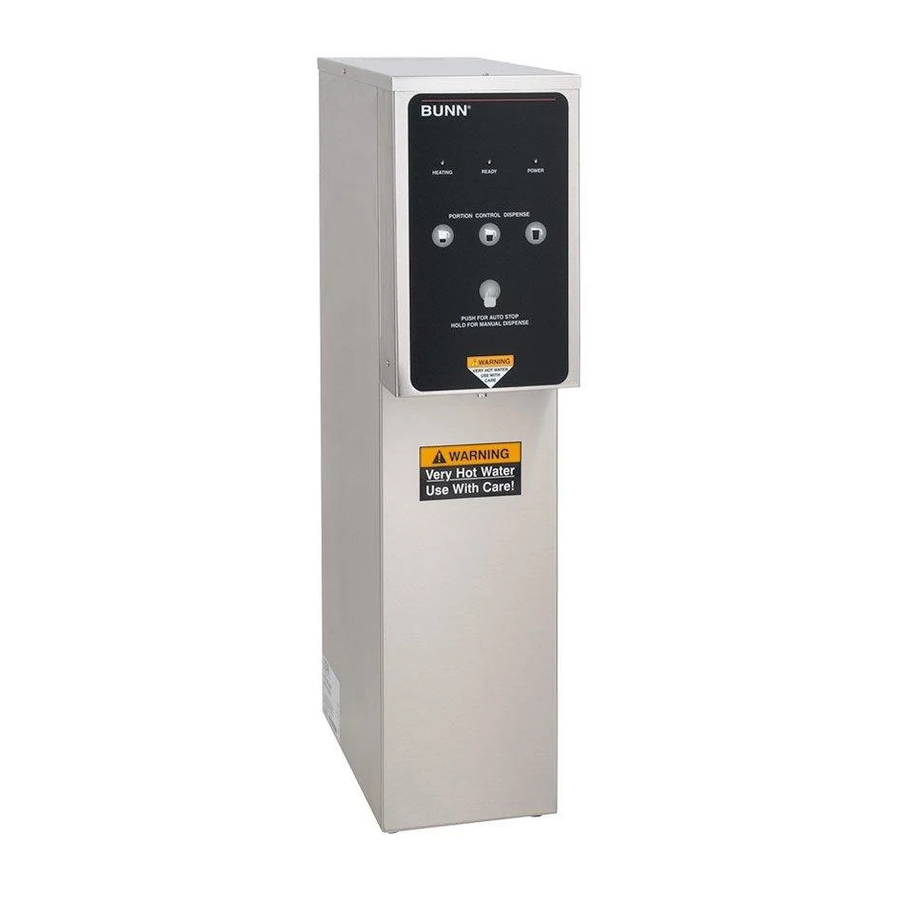
H10X/H5X
H5E/DV PC
H5 ELEMENT
With Digital Control Board
SERVICE MANUAL
BUNN-O-MATIC CORPORATION
POST OFFICE BOX 3227
SPRINGFIELD, ILLINOIS 62708-3227
PHONE: (217) 529-6601
FAX: (217) 529-6644
To ensure you have the latest revision of the manual or to obtain the illustrated parts catalog, please visit
the Bunn-O-Matic website, at www.bunn.com. This is absolutely FREE, and the quickest way to obtain
the latest catalog and manual updates. Contact Bunn-O-Matic Corporation at 1-800-286-6070 to obtain
a paper copy of the required Illustrated Parts Catalog mailed via U.S. Postal Service.
42311.0000B 05/11 © 2011 BUNN-O-MATIC CORPORATION
Advertisement
Table of Contents

Related Manuals for Bunn BUNN DV


Summary of Contents for Bunn BUNN DV
- Page 1 To ensure you have the latest revision of the manual or to obtain the illustrated parts catalog, please visit the Bunn-O-Matic website, at www.bunn.com. This is absolutely FREE, and the quickest way to obtain the latest catalog and manual updates. Contact Bunn-O-Matic Corporation at 1-800-286-6070 to obtain a paper copy of the required Illustrated Parts Catalog mailed via U.S.
- Page 2 SOLE OPTION AS SPECIFIED HEREIN, TO REPAIR, REPLACEMENT OR REFUND. In no event shall BUNN be liable for any other damage or loss, including, but not limited to, lost profi ts, lost sales, loss of use of equipment, claims of Buyer’s customers, cost of capital, cost of down time, cost of substitute equipment, facilities or services, or any other special, incidental or consequential damages.
-
Page 3: Table Of Contents
WARNING - Inspection, testing, and repair of electrical equipment should be performed only by qualifi ed service personnel. Disconnect the dispenser fromthe power source when servicing, except when electrical tests are required and the test procedure specifi cally states to connect the dispenser to the power source. TroubleShooting ... -
Page 4: Troubleshooting
TROUBLESHOOTING A troubleshooting guide is provided to suggest probable causes and remedies for the most likely problems encountered. If the problem remains after exhausting the troubleshooting steps, contact the Bunn-O-Matic Technical Service Department. • Inspection, testing, and repair of electrical equipment should be performed only by qualifi ed service person- nel. - Page 5 TROUBLESHOOTING (cont.) Problem Equipment will not operate (cont.) Automatic refi ll will not oper- ate after drawing hot water. Water fl ows into the tank con- tinuously (Dispenser discon- nected from power source). Water fl ows into the tank con- tinuously (Dispenser connect- ed to power source).
- Page 6 TROUBLESHOOTING (cont.) Problem Water boils continuously. CAUTION – Tanks and tank components should be delimed reglarly depending on local water conditions. Exces- sive mineral build-up on stainless steel surfaces can initiate corrosive reactions resulting in serious leaks. Dispenser is making unusual noises.
-
Page 7: Component Access
SERVICE WARNING – Disconnect the dispenser from the power source before the removal of any panel or the replacement of any component. WARNING - Inspection, testing, and repair of electrical equipment should be performed only by qualifi ed service personnel. Disconnect the dispenser fromthe power source when servicing, except when electrical tests are required and the test procedure specifi... -
Page 8: Electronic Controls
SERVICE Electronic Controls FIG. 8a ELECTRONIC CONTROL Triac Assy Electronic Control Board FIG. 8b ELECTRONIC CONTROL BOARD AND TRIAC Location: The electronic control board is located inside the rear of the dispenser. Access will also be needed to the temperature sensor, overfl ow tube temperature sensor, and liquid level probe located on the tank lid. - Page 9 SERVICE (cont.) Electronic Controls (cont.) Liquid Level Control Test Procedure 1. Disconnect the dispenser from the power source. 2. Check the voltage across terminals 3 & 4 of the electronic control board with a voltmeter. Connect the dispenser to the power source. The indication must be: a.) 100 to 120 volts ac for 100 to 120 volt models b.) 200 to 240 volts ac for 200 to 240 volt models...
- Page 10 Electronic Controls (cont.) 7. Reconnect the pink wire to terminal 5 of the elec- tronic control assembly. 8. Loosen the compression fi tting, remove the probe from the tank lid, and inspect it for mineral depos- its. Replace it if necessary. Keep the exposed ends of the probe away from any metal surface of the dispenser.
- Page 11 If voltage was present as described, the temperature control of the system is operating properly. If voltage was not present as described, contact Bunn-O-Matic to order an electronic control board and temperature sensor for evaluation and proceed to #9. 6. Replace the electronic control board.
-
Page 12: Limit Thermostat
SERVICE (cont.) Limit Thermostat Location: The limit thermostat is located on the tank lid. To test the limit thermostat, access will also be needed to the terminal block located at the rear of the dispenser. FIG. 12a LIMIT THERMOSTAT FIG. 12b LIMIT THERMOSTAT Test Procedure: 1. -
Page 13: Safety Overfl Ow Switch
SERVICE (cont.) Safety Overfl ow Switch FIG. 13a SAFETY OVERFLOW SWITCH FIG. 13b OVERFLOW PROTECTION SWITCH Location: The safety overfl ow switch is located inside the rear of the dispenser inside the copper overfl ow cup. For testing or removal of the safety overfl ow switch, access may also be needed by removing the two screws attaching the electronic control assembly to its mount- ing bracket. -
Page 14: Solenoid Valve (Late Models)
SERVICE (cont.) Solenoid Valve (Late Models) Location: The solenoid valve is located inside the rear of the dispenser on the right side near the bottom. To test the solenoid valve, access will also be needed to the electronic control board. F ill th e te r... -
Page 15: Solenoid Valve (Early Models)
SERVICE (cont.) Solenoid Valve (Early Models) Location: The solenoid valve is located behind the large access panel on the left side of the dispenser. To test the solenoid valve, access will also be needed to the electronic control board. H 10 FIG. -
Page 16: Tank Heater
SERVICE (cont.) Tank Heater Location: The tank heater is located in the tank lid. FIG. 16a TANK HEATER FIG. 16b TANK HEATER Test Procedure: 1. Disconnect the dispenser from the power source. 2. Check the voltage across the terminals of the tank heater with a voltmeter. -
Page 17: Steam Sensor
SERVICE (cont.) Steam Sensor (Thermistor) Location: The thermistor is located on the end of the overfl ow tube above the overfl ow cup. To test the thermistor, access will also be needed to the electronic control board. FIG. 17a LOCATION FIG. -
Page 18: Dispense Valve (Pc)
SERVICE (cont.) Dispense Valve (PC Only) Location: The Dispense Valve is located behind control panel. Dispense valve Flare nut FIG. 18a DISPENSE VALVE Test Procedures: 1. Check the valve for coil action. Turn on the valve with the dispense button. Listen carefully in the vicinity of the dispense valve for a click as the coil pulls the plunger in. -
Page 19: Electrical Schematic
PINK-22 J6-1 GRN-18 STEAM SENSOR J5-1 0-3.3VDC t° J4-1 0-3.3VDC J3-1 J1-1 J3-5 J1-5 H5-PC NO JUMPER WHT-14 REFILL WHT-18 WHT-18 DISPENSE USED ON H5X ONLY BLK-24 WHI-24 0-13.8VAC TANK t° STATIC SHIELD 39333.0000D 09/09 ©2006 BUNN-O-MATIC CORPORATION 42311 071310... - Page 20 DISPENSE VIO-18 230VAC PINK-22 J6-1 GRN-18 STEAM SENSOR J5-1 0-3.3VDC t° J4-1 0-3.3VDC J3-1 J1-1 J3-5 J1-5 H5-PC NO JUMPER RED-18 RED-18 USED ON H5X ONLY BLK-24 WHI-24 0-13.8VAC TANK t° STATIC SHIELD 39333.0001C 10/09 ©2006 BUNN-O-MATIC CORPORATION 42311 071310...
- Page 21 NO JUMPER Early H5E, H5X, H10X Install jumper thru ver. 1.04 NOTE: no jumper used on any Model starting with ver. 1.08 40707.0000C 09/09 © 2008 BUNN-O-MATIC CORPORATION L2 or N Earth Ground MAIN ON/OFF SWITCH (Late Models only) BLK-18...
- Page 22 J3-5 NO JUMPER Early H5E, H5X, H10X Install jumper thru ver. 1.04 NOTE: no jumper used on any Model starting with ver. 1.08 42375.0000A 09/09 © 2009 BUNN-O-MATIC CORPORATION Earth Ground MAIN ON/OFF SWITCH (Late Models only) Chassis Ground BLK-18...
- Page 23 FACTORY 0-3.3VDC USE ONLY Early H5E, H5X, H10X Install jumper thru ver. 1.04 NOTE: no jumper used on any Model starting with ver. 1.08 40712.0000F 05/11 © 2008 BUNN-O-MATIC CORPORATION GRN/YEL Earth Ground Chassis Ground BLK-14 LIMIT THERMOSTAT BLU-14 RFI SUPPRESSION...
- Page 24 SCHEMATIC WIRING DIAGRAM H5 ELEMENT TERMINAL BLOCK MASTER ON/OFF SWITCH WHI/BLU REFILL WHI/RED PINK J4-1 GRN/YEL STEAM SENSOR USED ON J3-1 t° H5X ONLY J2-1 J1-1 J1-5 44657.0000B 05/11 ©2011 BUNN-O-MATIC CORPORATION TEMP PROBE REFILL PROBE TANK t° 42311 050511...