Advertisement
Quick Links
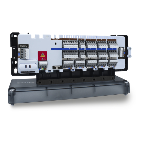
Control box extension for 5-zone UFH
Model: CB500X
Manual
SALUS Controls Plc
T: 01226 323961
Units 8-10 Northfield Business Park
E: sales@salus-tech.com
Forge Way, Parkgate
Rotherham, S60 1SD
United Kingdom
www.salus-controls.com
SALUS Controls is a member of the Computime Group.
Maintaining a policy of continuous product development SALUS Controls plc reserve the right to
change specification, design and materials of products listed in this brochure without prior notice.
AUG 2021
V15
Introduction
The CB500X extension module control box is an element of the underfloor heating / cooling control
system. The control box allows you to control 5 different zones. Number of controlled zones can be
increased up to 15 zones by connecting CB500X extension modules to the CB500 unit which is equipped
with a module system that controls the source of heating and cooling. Each individual zone can be
operated by one thermostat. Thermostat which require 230V power supply has to be powered directly
from control box. The spring clamps provide quick and convenient wiring connections. The control box is
designed to work with NC (normally-closed) type actuators. It is recommended to mount it on a surface
or on a DIN rail.
Product compliance
This product complies with the essential requirements and other relevant provisions of the following
EU Directives: EMC 2014/30/EU, Low Voltage Directive LVD 2014/35/EU and RoHS directive 2011/65/EU.
The full text of the EU Declaration of Conformity is available at the following internet address:
www.saluslegal.com.
Safety information
Use in accordance with current national and EU regulations. Device is intended for indoor use only in
dry conditions. Product for indoor use only. Installation must be carried out by a qualified person in
accordance to current national and EU regulations.
Before attempting to setup and install, make sure that the devices is not connected to any power
source. Installation must be carried out by a qualified person. Incorrect installation may cause damage
to the devices. The CB500X should not be installed in areas where it may be exposed to water or damp
conditions.
Technical Information
Power Supply
230 V AC
Total Load Max
1 A
Outputs
Actuators (AC 230V)
Dimensions [mm]
270 x 110 x 55
Control box description
1. Cartridge fuse 5 x 20 mm T2A
*
2. Power supply
3. NSB (Night Set Back reduction) function
6
6
1
*
WARNING! DO NOT connect power supply to the CB500X power supply input when it is connected together with CB500. CB500X power supply input have to be used only when control box extension works
as standalone device.
1. Fuse
Note: Replacement of the fuse to be carried out only when the control box is disconnected
from power supply (230 V ~).
Main fuse is located under the housing cover next to power supply terminals and secures the control box
and the devices connected to it. Use ceramic tube slow blow 250 V ROHS fuses (5x20 mm) with nominal
max current 2A. To replace fuse remove the fuse holder with a flat screwdriver and pull out the fuse.
2. Power Supply
Power supply for control box is 230 V ~ 50Hz.
Three wire installation should be made in accordance
with the current applicable regulations.
The
red
LED will illuminate
inidicating that the control box is
connected to the power supply.
230 V AC
L
N
4. Actuators output connections (AC 230V)
5. Thermostats input connections
6. CB500X extension input
4
3
2
5
3. NSB (Night Set Back reduction) function
The NSB (Night Set Back) function enables you automatically reduce the setpoint temperature on
non-programmable thermostats via programmable thermostat connected to the same control box or an
extension module. NSB function changes comfort to economic setpoint temperatures for each thermostat
individually. The programmable thermostat, e.g. installed in the living room, sends a signal to the
non-programmable thermostats through a control box (by wires). Then, the non-programmable
thermostats automatically reduce the setpoint temperature according to the value set on them. The NSB
terminal is marked with the clock icon - all NSB terminals are connected together within control box. The
NSB function works only in a 4-wire installations (see connection diagrams).
4. Actuators connection
Actuators wires should be plugged into the spring clamps of the respective zones. Maximum current load
for each zone is designed to handle up to 6 actuators with a power of 2W each. With more actuators in
one zone, an additional relay should be used to make sure that actuators output will be not overloaded.
Example based on T30NC 230 V actuators
6
3
Note: Depends on the
thermostat heating/cooling
state - 230 V AC may appear
on the actuators output.
Advertisement

Related Manuals for Salus CB500X


Summary of Contents for Salus CB500X
- Page 1 Maintaining a policy of continuous product development SALUS Controls plc reserve the right to WARNING! DO NOT connect power supply to the CB500X power supply input when it is connected together with CB500. CB500X power supply input have to be used only when control box extension works change specification, design and materials of products listed in this brochure without prior notice.
- Page 2 230 V AC 230V AC power is supplied only to the main CB500 control box. A maximum of two CB500X extension modules can be connected to the EXTENSION input of the main CB500 control box using a 4-wire cable (230V) - please pay attention to the terminal markings.