Bunn FMD-2 Operating & Service Manual
Bunn hot beverages or soups operating & service manual fmd-1, fmd-2
Hide thumbs
Also See for FMD-2:
- Operating & service manual (36 pages) ,
- Illustrated parts catalog (24 pages) ,
- Service & repair manual (71 pages)
Table of Contents
Advertisement
Quick Links
Download this manual
See also:
Service & Repair Manual
BUNN
OPERATING & SERVICE MANUAL
BUNN-O-MATIC CORPORATION
29112.0000 5/00 ©1998 Bunn-O-Matic Corporation
O N
T T
R E
B U
D
N
O L
H E
d H
, T
L L
a n
F U
S H
2 /3
P U
IS
L L
F U
2 /3
P IS
C U
E N
W H
N
T O
U T
E B
A S
E
L E
A C
E
R E
P L
E R
P H
C U
POST OFFICE BOX 3227
SPRINGFIELD, ILLINOIS 62708-3227
PHONE: (217) 529-6601 FAX: (217) 529-6644
®
P
C U
T IL
U N
E
A S
L E
FMD-1
FMD-2
S/N FMD0013000-UP
P
C U
T IL
U N
E
N
A S
T O
L E
U T
R E
D B
N
O L
H E
, T
d H
L L
a n
F U
S H
2 /3
P U
IS
L L
F U
2 /3
P IS
C U
N
H E
N W
T O
U T
E B
A S
E
A C
L E
E
P L
E R
R E
P H
C U
E
A C
P L
E
E R
P H
C U
Advertisement
Table of Contents

Related Manuals for Bunn FMD-2


Summary of Contents for Bunn FMD-2
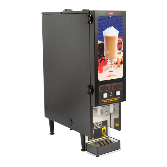
- Page 1 BUNN OPERATING & SERVICE MANUAL BUNN-O-MATIC CORPORATION SPRINGFIELD, ILLINOIS 62708-3227 PHONE: (217) 529-6601 FAX: (217) 529-6644 29112.0000 5/00 ©1998 Bunn-O-Matic Corporation ® T IL 2 /3 2 /3 P IS POST OFFICE BOX 3227 FMD-1 FMD-2 S/N FMD0013000-UP T IL...
- Page 2 SPECIFIED HEREIN, TO REPAIR OR, AT BUNN’S SOLE OPTION, REPLACEMENT OR REFUND. In no event shall Bunn be liable for any other damage or loss, including, but not limited to, lost profits, lost sales, loss of use of equipment, claims of Buyer’s customers, cost of capital, cost of down time, cost of substitute equipment, facilities or services, or any other special, incidental or consequential damages.
- Page 3 USER NOTICES (Cont.) 00656.0000 00831.0000 27096.0000 FMD-1 ONLY 28368.0001 PUSH and HOLD BUTTON UNTIL CUP PUSH and HOLD BUTTON UNTIL CUP IS 2/3 FULL, THEN RELEASE IS 2/3 FULL, THEN RELEASE 28964.0000 28964.0001 29112 101598...
- Page 4 It can be purchased direct from Bunn-O-Matic (part number 00326-0000). Bunn-O-Matic does not recommend the use of a saddle valve to install the brewer. The size and shape of the hole made in the supply line by this type...
- Page 5 The system automatically maintains the hot water tank’s level by energizing the refill solenoid when the water level drops below the liquid level probe. If the system for the FMD-2 only has not successfully refilled in 7 1/2 minutes, a refill error occurs.
- Page 6 COLD BEVERAGE SET-UP (OPTIONAL FMD-2 ONLY) Cold beverages may be dispensed from the left dispense position as follows: 1. Disconnect the dispenser from the power source. 2. Remove the lower front access panel. 3. Locate the Hot/Cold jumper connection near the whipper panel in the main wiring harness.
- Page 7 6. Insert a tube to the bottom of the tank and syphon ALL of the water out. (Bunn-O-Matic has a syphon assembly #12440.0000 available for this purpose.) NOTE - The dispenser must be refilled using the INITIAL FILL & HEAT steps before reconnecting to the power source.
- Page 8 TROUBLESHOOTING A troubleshooting guide is provided to suggest probable causes and remedies for the most likely problems encountered. If the problem remains after exhausting the troubleshooting steps, contact the Bunn-O-Matic Technical Service Department. • Inspection, testing, and repair of electrical equipment should be performed only by qualified service personnel.
- Page 9 6. A) Level Control Board and Probe - FMD-1 B) Control Board and Probe - FMD- 7. A) Auger Drive - FMD-1 B) Auger Drive - FMD-2 8. Water Strainer 9. Lime build-up CAUTION - Tank and tank compo- nents should be delimed regularly depending on local water conditions.
- Page 10 TROUBLESHOOTING (cont.) PROBLEM Water is not hot (Cont.) Spitting or excessive steaming Dripping from dispense tip Water flows into tank continuously PROBABLE CAUSE 4. Tank Heater Switch 1. Lime build-up CAUTION - Tank and tank compo- nents should be delimed regularly depending on local water conditions.
- Page 11 7. Auger Motor - FMD-1 Auger Motor - FMD-2 8. Rinse/Run Switch - FMD-1 Rinse/Run Switch - FMD-2 9. Rinse Timer - FMD-2 REMEDY Refer to Service - Dispense Switch for testing procedures. See page 21 Remove the solenoid valve and clear any obstructions.
- Page 12 PROBABLE CAUSE 1. Plumbing Lines 2. Water Supply 3. Tank Heater 1. Fan 2. A) Hopper Drive Board - FMD-1 B) Control board - FMD-2 1. Lamp 2. Lamp Holder 3. Starter - Lamp 4. Ballast REMEDY Plumbing lines should not be rest- ing on the counter top.
-
Page 13: Table Of Contents
Level Control Board and Level Probe (FMD-1) ... 29 Limit Thermostat ... 31 Rinse/Run Switch (FMD-1) ... 31 Rinse/Run Switch (FMD-2) ... 32 Solenoid (Cold Water - Optional FMD-2 Only) ... 33 Solenoid (Dispense) ... 34 Solenoid (Inlet) ... 35 Tank Heater ... 36 Tank Heater Switch ... - Page 14 SERVICE AUGER DRIVE COMPONENTS - FMD-1 (CONT.) 5. Check the voltage across the positive (red wire) terminal and the negative (black wire) terminal on the auger motor with a voltmeter. With the rinse/ run switch in the run (lower) position press and hold the dispense switch.
-
Page 15: Auger Drive Components (Fmd-1)
Control Board (+) BLK to Hopper Speed Control Board (-) FIG. 3 AUGER MOTOR TERMINALS AUGER DRIVE COMPONENTS - FMD-2 FIG. 4 AUGER DRIVE COMPONENTS Location The auger components are located inside the bottom part of the hopper except for the auger drive bracket, washer and locknut, which are located on the outside bottom rear of the hopper. - Page 16 SERVICE (cont.) AUGER DRIVE COMPONENTS - FMD-2 (CONT.) 4. Disconnect the dispenser from the power supply. If voltage is present as described and the auger does not turn, replace the auger motor. If voltage is not present as described, refer to the wir- ing diagrams and check the dispenser wiring harness.
- Page 17 SERVICE (cont.) AUGER DRIVE COMPONENTS - FMD-2 (cont.) Auger Drive Motor (Refer to Fig. 5) 1. Remove all hopper assemblies (20) and set aside for reassembly. 2. Remove the four #8-32 screws securing the hop- per support plate (19), remove plate and set aside for reassembly.
-
Page 18: Ballast
SERVICE (cont.) BALLAST - FMD-1 & FMD-2 (cont.) Location FMD-1 The front door lamp ballast is located behind the front access panel on the left front side of the com- ponent bracket. FMD-2 The front door lamp ballast is located behind the front access panel on the left rear side of the com- ponent bracket. -
Page 19: Control Board (Fmd-2)
SERVICE (cont.) CONTROL THERMOSTAT - FMD-1 & FMD-2 (cont.) a) 120 volts ac for two wire 120 volt models. b) 208 volts ac for three wire 120/208 volt models. c) 240 volts ac for three wire 120/240 volt models. 5. Disconnect the dispenser from the power source. - Page 20 SERVICE (cont.) CONTROL BOARD - FMD-2 ONLY (CONT.) 6. Disconnect the four pin connector from J4 of the control board. 7. Check the voltage across pins 1 & 4 of the four pin connector on the wiring harness with a voltmeter.
-
Page 21: Dispense Switch
SERVICE (cont.) CONTROL BOARD - FMD-2 ONLY (CONT.) 7. Check the voltage across the red (+) terminal and the black (-) terminal of the auger motor with a voltmeter. Connect the dispenser to the power source. Press and hold the appropriate dispense switch. - Page 22 SERVICE (cont.) DISPENSE SWITCH(S) - FMD-1 & FMD-2 (cont.) Test Procedure: FMD-1 1. Disconnect the dispenser from the power source. 2. Open the dispenser door and remove the bottom door cover. 3. Disconnect the wires from the door interconnect wiring harness to the dispense switch.
-
Page 23: Fan
SERVICE (cont.) DISPENSE SWITCH(S) - FMD-1 & FMD-2 (cont.) FMD-1 RED/WHI LEFT FMD-2 BLU/WHI FIG. 14 DISPENSE SWITCH TERMINALS FAN - FMD-1 & FMD-2 FIG. 15 FAN Location: ing on the right rear of the dispenser base plate. Test Procedures: 1. -
Page 24: Frother
2. Disconnect the red and white wires (FMD-1 & FMD-2 left motor) or orange and white wires (FMD-2 right motor) of the main harness from the black leads of the motor. 3. Press and hold the dispense switch and check the voltage across the disconnected harness wires with a voltmeter. - Page 25 SERVICE (cont.) FROTHER AND WHIPPER MOTOR - FMD-1 (shown) & FMD-2 (cont.) 5. Remove the steam collector (1) by pulling it for- ward and at the same time twisting it clockwise. 6. Pull the mixing chamber (2) out of the whipper chamber (4).
-
Page 26: Hopper Drive Board(Fmd-1)
SERVICE (cont.) HOPPER DRIVE BOARD - FMD-1 ONLY FIG. 20 HOPPER DRIVE BOARD Location The hopper drive board is located inside the dispenser mounted on the auger motor mounting bracket. Test Procedures: 1. Disconnect the dispenser from the power source. 2. -
Page 27: Increase/Decrease Switch (Fmd-2)
RED/WHI from Main Harness WHI from Main Harness FIG. 21 HOPPER DRIVE BOARD TERMINALS INCREASE/DECREASE SWITCH - FMD-2 ONLY FIG. 22 INCREASE/DECREASE SWITCH Location: The increase/decrease switch is located on the lower left front of the whipper motor mounting panel. -
Page 28: Lamp Holder
SERVICE (cont.) LAMP HOLDER - FMD-1 (shown) & FMD-2 FIG. 24 LAMP HOLDERS Door Assy Upper Panel Lamp Holders Lower Panel Lamp Starter W/Socket Location: The lamp holders are located on the front of the upper panel behind the display panel. -
Page 29: Lamp Starter And Socket
SERVICE (cont.) LAMP REPLACEMENT (Refer to Fig.24)(cont.) 9. Reconnect the plug on the door wiring harness to the connector on the door interconnect wiring harness. 10. Install the door lower panel (5) using four #8-32 screws. LAMP STARTER and SOCKET (Refer to Fig. 24) Location: The lamp starter (6) is located inside the door assy (1) on the top of the door lower panel (5). - Page 30 SERVICE (cont.) LEVEL CONTROL BOARD AND LEVEL PROBE - FMD-1 ONLY (cont.) Test Procedure: 1. Disconnect the dispenser from the power source. 2. Remove the violet wire from terminal 1 & pink wire from terminal 4 of the circuit board. 3.
-
Page 31: Limit Thermostat
SERVICE (cont.) LIMIT THERMOSTAT - FMD-1 (shown) & FMD-2 FIG. 27 LIMIT THERMOSTAT Location: The limit thermostat is located in the center of the tank lid. Test Procedures: Disconnect the dispenser from the power source. Disconnect both black wires from the limit ther- mostat. -
Page 32: Rinse/Run Switch (Fmd-2)
RED from Main Wiring Harness WHI/RED to Main Harness FIG. 30 RINSE/RUN SWITCH TERMINALS RINSE/RUN SWITCH - FMD-2 FIG. 31 RINSE/RUN SWITCH Location: The rinse/run switch is located on the lower center of the whipper motor mounting panel. Test Procedures: Disconnect the dispenser from the power source. - Page 33 SERVICE (cont.) SOLENOID VALVE (COLD WATER OPTIONAL)(FMD-2 ONLY) FIG. 33 COLD WATER SOLENOID VALVE Location: The cold water solenoid valve is located on the left side of the dispenser base just behind the com- ponent bracket. Test Procedures: Disconnect the dispenser from the power source.
- Page 34 SERVICE (cont.) SOLENOID VALVE (DISPENSE) - FMD-1 & FMD-2 FMD-1 FMD-2 FIG. 36 DISPENSE SOLENOID VALVE Location: The dispense solenoid is located on the upper left center of the tank. Test Procedures: Disconnect the dispenser from the power source. For FMD-1 disconnect the red and white wires from the solenoid valve.
- Page 35 SERVICE (cont.) SOLENOID VALVE (DISPENSE) - FMD-1 & FMD-2 (cont.) Remove panel and set aside. 3. Remove the two #8-32 securing the auger motor mounting panel to the dispenser housing and the two rear #8-32 screws from the side panels.
-
Page 36: Solenoid (Cold Water - Optional Fmd-2 Only)
SERVICE (cont.) SOLENOID VALVE (INLET) - FMD-1 & FMD-2 (cont.) 7. Disconnect the dispenser from the power source. If the sound is heard as described and water will not pass through the solenoid valve, there may be a blockage in the water line before the solenoid valve or, the solenoid valve may require inspection for wear, and removal of waterborne particles. -
Page 37: Tank Heater
SERVICE (cont.) TANK HEATER - FMD-1 (shown) & FMD-2 (cont.) NOTE - If the tank heater remains unable to heat, remove and inspect heater for cracks in the sheath. Removal and Replacement: 1. Disconnect the dispenser from the power source. - Page 38 BLK to Main Harnesss BLK from Main Harness FIG. 42 TANK HEATER SWITCH TERMINALS TRANSFORMER - FMD-2 ONLY FIG. 43 TRANSFORMER Location: The transformer is located behind the lower front access cover, mounted on the right rear side of the component bracket.
- Page 39 DISPENSE FLUORESCENT LAMP BALLAST CHASSIS DOOR 120 VOLTS A C - 2 WIRE 120/208-240 VOLTS AC - 3WIRE SINGLE PHASE 29096.0000C 8/98 © 1998 BUNN-O-MATIC CORPORATION CONTROL LIMIT THERMOSTAT TANK HEATER BLK-16 BLK-16 HOPPER SPEED ADJUST WHI/RED 1 2 3...
-
Page 40: Tank Heater Switch
RIGHT HOPPER LEFT HOPPER JUMPER PLUG MUST BE USED WHEN COLD DRINK FEATURE NOT INSTALLED 120 VOLTS AC - 2 WIRE 120/208-240 VOLTS AC - 3 WIRE SINGLE PHASE, 60 HZ 29096.0001C 10/98 © 1998 BUNN-O-MATIC CORPORATION STARTER 29112 101598...