Table of Contents
Advertisement
Quick Links
Manual
Model 3301T
Digital Instrumentation
» Software Device Profile: 103.0.0.0 «
Curtis Instruments, Inc.
200 Kisco Avenue
Mt. Kisco, NY 10549
www.curtisinstruments.com
Read Instructions Carefully!
Specifications are subject to change without notice.
© 2021 Curtis Instruments, Inc. ® Curtis is a registered trademark of Curtis Instruments, Inc.
© The design and appearance of the products depicted herein are the copyright of Curtis Instruments, Inc.
53245 Rev A September 2021
Advertisement
Table of Contents

Summary of Contents for Curtis 3301T
- Page 1 Specifications are subject to change without notice. © 2021 Curtis Instruments, Inc. ® Curtis is a registered trademark of Curtis Instruments, Inc. © The design and appearance of the products depicted herein are the copyright of Curtis Instruments, Inc. 53245 Rev A September 2021...
-
Page 2: Table Of Contents
OPEN THE 3301T’S MAIN MENU .................... 10 OPEN THE 3301T’S PARAMETER MENUS ................10 OPEN READ-WRITE PARAMETER MENUS FOR OTHER CURTIS DEVICES ........12 OPEN READ-ONLY PARAMETER MENUS OF DEVICES CONNECTED TO THE SERIAL PORT ..13 USING THE PARAMETER MENU SCREENS ................13 ALARM BUZZER ........................... - Page 3 TABLE OF CONTENTS cont’d PRESET USER INTERFACES — 3301T-7001 MODEL ..............15 SPEED MODE ........................17 SIGNAL ICONS ........................17 DIRECTION ICONS ......................... 18 BDI ............................18 SPEEDOMETER ........................19 CARGO WEIGHT AND LIFT HEIGHT ..................19 CONTROLLER HOUR METERS ....................19 KEYSWITCH HOUR METER .....................
- Page 4 MISC MENU ..........................42 5: MONITOR PARAMETERS ........................ 43 HOURMETERS MENU ........................43 MAINTENANCE MENU ........................44 ODOMETERS MENU ........................44 SENDERS MENU .......................... 44 OUTPUT MENU ..........................45 TEMPERATURE MENU ........................45 pg. iv Curtis Model 3301T Digital Instrumentation – September 2021...
- Page 5 PDO TIMING .......................... 48 PRECONFIGURED PDOS ......................49 STANDARD CANOPEN OBJECTS ....................53 DISPLAY HOUR METERS OBJECT ....................54 APPENDIX A: CURTIS PROGRAMMING DEVICES .................. 55 APPENDIX B: SPECIFICATIONS ......................57 pg. v Curtis Model 3301T Digital Instrumentation – September 2021...
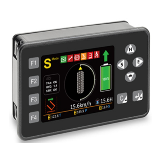
- Page 6 FIGURE 1 CURTIS 3301T HMI ......................1 FIGURE 2 COUNTERBALANCED FORKLIFTS APPLICATION — 3301T-7001 .......... 15 FIGURE 3 REACH TRUCKS AND ORDER PICKERS APPLICATION — 3301T-7001 ........16 FIGURE 4 SPEEDOMETER — COUNTERBALANCED FORKLIFTS ............19 FIGURE 5 SPEEDOMETER — REACH TRUCKS AND ORDERS PICKERS ..........19 FIGURE 6 MOUNTING DIMENSIONS ....................
-
Page 7: 1: Overview
An LCD heater is optional for operation in cold temperatures. Vehicle operators use buttons to work with the user interface. The buttons make the 3301T ideal for gloved operators and for applications that require precise tactile feedback. -
Page 8: Using This Manual
• Hour meter: Hour meters provide a resolution of 0.1 hours and a maximum of 99999.9 hours. There are four hour meters: one is for the 3301T and three are for Curtis devices on the CANbus. -
Page 9: Programming
The 3301T provides the basic functions of the Curtis 1313 Handheld Programmer. Users can read and write parameters for the 3301T and for other Curtis devices that are on the CANbus or connected through the serial port. For more information, see View and Edit Parameters. -
Page 10: Conventions
Curtis Model 3301T Digital Instrumentation – September 2021 Return to TOC CONVENTIONS The following topics describe terms and notations used in this manual. Numeral System Notation The following table describes how this manual denotes decimal, binary, and hexadecimal numbers. Note: The letter n in the format column represents a digit. -
Page 11: 2: Using The 3301T
Return to TOC 2 — USING THE 3301T This chapter describes how to use the 3301T’s buttons and screens. BUTTONS The following table describes the 3301T’s buttons. The buttons’ functions depend upon which screen is active. Button Home Screen Parameter Menu Screens Password Screens Specifies the high speed mode. -
Page 12: Power-On 3301T Password Or Ecs Authorization
Curtis Instruments website. The following topics describe the two methods. Power-On 3301T Password If the 3301T is configured to require a password after the device is powered on, the following screen is displayed: pg. 6 2 — USING THE 3301T... - Page 13 Curtis Model 3301T Digital Instrumentation – September 2021 Return to TOC If this screen is visible, take the following steps to access the 3301T: 1. Use the F1–F4 buttons to enter the four-digit password, which consists of the numbers 1–4.
-
Page 14: Ecs Authorization
Return to TOC ECS Authorization If the 3301T is configured to allow only authorized ECS users to access the device, the following screen is displayed when a user is not logged onto the ECS: If this screen is visible, log onto the ECS by swiping an RFID tag or by entering an ECS user ID and PIN code on the ECS keypad. -
Page 15: View Fault Names
VIEW AND EDIT PARAMETERS You can use the 3301T to view and edit parameters for the 3301T and for other Curtis devices connected through the CANbus or the serial port. The 3301T parameters are contained by the menus described in the... -
Page 16: Open The 3301T's Main Menu
Open the 3301T’s Parameter Menus You must enter a password to open all of the 3301T’s menus, which include the main menu, Program menu, and Monitor menu. Take the following steps to open these menus. 1. Go to the home screen. - Page 17 Curtis Model 3301T Digital Instrumentation – September 2021 Return to TOC 3. To change the active access level, press the , or button. 4. Use the F1–F4 buttons to enter the four-digit password, which consists of the numbers 1–4. Pressing an F1–F4 button enters the number that follows the letter “F”...
-
Page 18: Open Read-Write Parameter Menus For Other Curtis Devices
Open Read-Write Parameter Menus for Other Curtis Devices The 3301T allows you to view and edit parameters of Curtis devices that are connected through the CANbus or that support the ESP/SP protocol and are connected through the serial port. Take the following steps to open other Curtis devices’... -
Page 19: Open Read-Only Parameter Menus Of Devices Connected To The Serial Port
Open Read-Only Parameter Menus of Devices Connected to the Serial Port The 3301T provides read-only access to the main and Monitor menus of Curtis devices that support the ESP/SP protocol and are connected through the serial port. Take the following steps to open these menus: 1. - Page 20 Curtis Model 3301T Digital Instrumentation – September 2021 Return to TOC In addition, you can rapidly change parameter values by factors of 10, 100, or 1000 times the parameter’s step size. For example, suppose that you need to increase a parameter’s value by 1000 step sizes.
-
Page 21: Alarm Buzzer
Curtis Model 3301T Digital Instrumentation – September 2021 Return to TOC ALARM BUZZER The 3301T has a buzzer that emits sounds through the rear of the device. The buzzer is activated when the 3301T receives a fault code through the CANbus or through the fault code inputs for the DC traction and pump controllers. -
Page 22: Figure 3 Reach Trucks And Order Pickers Application - 3301T-7001
Curtis Model 3301T Digital Instrumentation – September 2021 Return to TOC Figure 3 Reach Trucks and Order Pickers Application — 3301T-7001 The following table describes the areas contained by the home screens. Unless otherwise indicated, these areas are contained by both home screens. -
Page 23: Speed Mode
Right hand Roadway mode Oil filter Chain Lift lockout Fault active Note: The fault icon blinks when a fault is detected or when the 3301T is not receiving fault signals from other devices. 2 — USING THE 3301T pg. 17... -
Page 24: Direction Icons
Curtis Model 3301T Digital Instrumentation – September 2021 Return to TOC Direction Icons The following icons indicate the vehicle’s direction: Icon Description Forward Backward Neutral Left turn Right turn The BDI area uses the following gauges to indicate the battery’s state of charge. The gauge colors... -
Page 25: Speedometer
The counterbalanced forklifts application can be configured to display the vehicle’s cargo weight or lift height or both: Controller Hour Meters The 3301T-7001 provides hour meters for the controllers listed in the following table: Icon Hour Meter Pump controller hour meter... -
Page 26: Keyswitch Hour Meter
Curtis Model 3301T Digital Instrumentation – September 2021 Return to TOC Keyswitch Hour Meter The keyswitch hour meter indicates the number of hours that the 3301T’s keyswitch has been on since the hour meter was last reset: Steering Angle Both preset user interfaces provide gauges that display the steering angle; however, the gauges have different appearances. -
Page 27: Forklift Status
Curtis Model 3301T Digital Instrumentation – September 2021 Return to TOC A fault code displays if a component has active faults. In the following example, the steering controller has an active fault identified by the fault code 1, 8: Note: The 3301T also displays fault names. See View Fault Names. -
Page 28: 3: Installation And Wiring
This chapter explains how to install and wire the 3301T. INSTALLING THE 3301T Install the 3301T in a location that will keep the device clean and dry. The recommended panel cutout is 74.3 + 0.8/–0 × 125.3 + 0.8/–0 mm, with a panel thickness between 2.0–4.0 mm. -
Page 29: I/O Connector
The mating connector is a 16-pin Mini-Universal MATE-N-LOK housing from TE Connectivity. The face is sealed to IP65. The rear is sealed to IP65 for electronic components and IP40 for the connector. Curtis recommends that you increase the connector’s protection to IP54 by using the parts listed in Table 4. -
Page 30: I/O Pins
Curtis Model 3301T Digital Instrumentation – September 2021 Return to TOC I/O PINS Table 5 I/O Pins Signal Name Description SCI Rx Serial communications — Rx. SCI GND Serial communications — ground. CAN_L CAN low. CAN_L Termination CAN 120Ω termination resistor — low. -
Page 31: Wiring Diagram
Note: The diagram may differ from your application’s requirements. However, the controller provides the I/Os and programmable parameters needed to meet almost all requirements. To discuss how to implement your application, contact your Curtis distributor or the Curtis sales and support office in your region. -
Page 32: Operating Voltage
9VDC 10VDC 12–96VDC 120VDC Applying B+ voltages above 120V may damage the 3301T and is not recommended. The device is designed to withstand continuous reverse polarity connections. Note: All voltages listed in this manual are DC voltages. OPERATING CURRENT The following tables describe the B+ pin’s operating current with the LCD heater off and on: Table 6 Operating Current —... -
Page 33: Battery Connections
Return to TOC BATTERY CONNECTIONS Connect the battery to the B+ and B– inputs (pins 16 and 15). Curtis recommends that you include a fuse in the circuit that connects the battery to the B+ input, as shown in Figure 7. -
Page 34: Fault Code Inputs
CAN CONNECTIONS To connect the 3301T to the CANbus, connect CAN Low and CAN High to pins 3 and 11, respectively. Use twisted-pair wiring to minimize the likelihood of picking up a voltage bias on only one signal. -
Page 35: 4: Programmable Parameters
Curtis Model 3301T Digital Instrumentation – September 2021 Return to TOC 4 — PROGRAMMABLE PARAMETERS MAIN MENU........p. 31 BDI MENU......... p. 37 OUTPUT MENU........p. 40 — Model Number — Nominal Voltage — Output Mode — Serial Number — Charge Full — Driver Output Setting —... - Page 36 Curtis Model 3301T Digital Instrumentation – September 2021 Return to TOC The programmable parameters allow you to configure the 3301T so that it meets your application’s requirements. Curtis programming devices provide a user-friendly way to read and write to the parameters.
-
Page 37: Main Menu Parameters
Curtis Model 3301T Digital Instrumentation – September 2021 Return to TOC MAIN MENU PARAMETERS The 3301T’s main menu contains the following parameters: MAIN MENU PARAMETER VALUES ACCESS LEVEL CAN INDEX RAW VALUES DATA SIZE DEFAULT VALUE DESCRIPTION Model Number –32768 to 32767... -
Page 38: Set Hourmeters Menu
Set Hourmeters submenu is displayed. The submenu contains parameters that reset the hour meters. Note: The default password for resetting the hour meters is 1234. Curtis recommends that you change the default password. Take the following steps to specify the password: 1. -
Page 39: Can Menu
Curtis Model 3301T Digital Instrumentation – September 2021 Return to TOC CAN MENU The following table describes the parameters on the CAN menu. Note: The CAN menu also contains the RPDO 1–4 Byte Map and TPDO 1–4 Byte Map menus, which specify the objects for which the PDOs transmit and receive data. -
Page 40: Rpdo And Tpdo Byte Map Menus
Curtis Model 3301T Digital Instrumentation – September 2021 Return to TOC RPDO and TPDO Byte Map Menus The parameters on the RPDO 1–4 Byte Map and TPDO 1–4 Byte Map menus are used to configure PDOs. RPDO 1–3 and TPDO 1–2 are preconfigured to transmit and receive messages; see Preconfigured PDOs. -
Page 41: Table 8 Pdo Byte Map Menus - Can Indexes And Default Values
Curtis Model 3301T Digital Instrumentation – September 2021 Return to TOC Table 8 PDO Byte Map Menus — CAN Indexes and Default Values PARAMETER CAN INDEX DEFAULT VALUE 0x1600:00 Length RPDO1 Map 1 RPDO1 0x1600:01 0x66010008 Map 2 RPDO1 0x1600:02... - Page 42 Curtis Model 3301T Digital Instrumentation – September 2021 Return to TOC Table 8 PDO Byte Map Menus — CAN Indexes and Default Values, cont’d PARAMETER CAN INDEX DEFAULT VALUE 0x1A02:00 Length TPDO3 Map 1 TPDO3 0x1A02:01 Map 2 TPDO3 0x1A02:02...
-
Page 43: Bdi Menu
Curtis Model 3301T Digital Instrumentation – September 2021 Return to TOC BDI MENU The source of the BDI percentage displayed by the 3301T can be either the 3301T’s internal BDI calculations or RPDO1. The parameters on the BDI menu are used for the internal calculations. BDI MENU... -
Page 44: Password Menu
Curtis Model 3301T Digital Instrumentation – September 2021 Return to TOC PASSWORD MENU The Password parameters specify the passwords for powering on the 3301T and for viewing and editing parameters. Note: The passwords’ ranges of values are 1111–4444. However, passwords can only consist of the digits 1, 2, 3, and 4. -
Page 45: Odometers Menu
Curtis Model 3301T Digital Instrumentation – September 2021 Return to TOC ODOMETERS MENU The 3301T provides three odometers. The Odometers parameters reset the odometers. Note: The parameters on the Odometers menu of the Monitor menu indicate the odometer data. ODOMETERS MENU... -
Page 46: Output Menu
Curtis Model 3301T Digital Instrumentation – September 2021 Return to TOC OUTPUT MENU The Output Mode parameter specifies how pin 8 (Switch Input5/MOSFET OUTPUT) is used. The Driver Output Setting parameter and the parameters on the following submenus apply when the pin is used as a driver: •... -
Page 47: Initial Menu
Curtis Model 3301T Digital Instrumentation – September 2021 Return to TOC Initial Menu The following table describes the parameters on the Initial menu. INITIAL MENU PARAMETER VALUES ACCESS LEVEL CAN INDEX RAW VALUES DATA SIZE DEFAULT VALUE DESCRIPTION Initial PWM Duty 0.0–100.0%... -
Page 48: Pi Menu
Curtis Model 3301T Digital Instrumentation – September 2021 Return to TOC PI Menu The 3301T has a proportional/integral current controller, which is configured by the parameters on the PI menu. PI MENU PARAMETER VALUES ACCESS LEVEL CAN INDEX RAW VALUES... -
Page 49: 5: Monitor Parameters
Curtis Model 3301T Digital Instrumentation – September 2021 Return to TOC 5 — MONITOR PARAMETERS HOURMETERS MENU......p. 43 SENDERS MENU........ p. 44 — Hourmeter 1 — Sender 1 — Hourmeter 2 — Sender 2 — Hourmeter 3 — Sender 3 — Hourmeter 4 —... -
Page 50: Maintenance Menu
Curtis Model 3301T Digital Instrumentation – September 2021 Return to TOC MAINTENANCE MENU The following table describes the parameters on the Maintenance menu. MAINTENANCE MENU PARAMETER VALUES CAN INDEX RAW VALUES DATA SIZE ACCESS LEVEL DESCRIPTION Maintenance 1 0–3276.7 hours... -
Page 51: Output Menu
Curtis Model 3301T Digital Instrumentation – September 2021 Return to TOC OUTPUT MENU The following table describes the parameters on the Output menu. OUTPUT MENU PARAMETER VALUES CAN INDEX RAW VALUES DATA SIZE ACCESS LEVEL DESCRIPTION PWM Duty 0.0–100.0% 16-bit... -
Page 52: 6: Canopen Communications
334C-01h: Control Byte Index Sub-index Data Strings are read from left to right. The following example shows how the 3301T transmits an SDO segment for the string “3301T-7”: Control Byte Data 33h = “3” 33h = “3”... -
Page 53: Node Ids
Return to TOC NODE IDS The 3301T’s node ID is specified with the CAN Node ID parameter. The default node ID is 0x2E. If the Curtis Electronic Code Switch (ECS) is on the CANbus, the ECS CAN Node ID parameter specifies its node ID. -
Page 54: Pdos
PDOs. The following list describes the PDOs’ event times: • RPDOs: 60,000ms (1 minute). If the 3301T does not receive data within one minute, the LCD will display *.* to indicate that data is not being received. -
Page 55: Preconfigured Pdos
• 4: Whether the data for the seat icon is from pin 5 (Switch Input1/Analog Input1/Frequency Input 1) or the CANbus. 0b indicates pin 5. • 5: Whether BDI data is from the 3301T or from the CANbus. 0b indicates the data is from the 3301T. - Page 56 • 6–7: Reserved. The BDI percentage. 2–5 The keyswitch hour meter data. The 3301T hour meters provide a resolution of 0.1 hours. For example, F423Fh indicates 99999.9 hours. The vehicle unlock control status. 0b = lock, 1b = unlock. Reserved.
- Page 57 Curtis Model 3301T Digital Instrumentation – September 2021 Return to TOC RPDO2 Byte(s) Description The following bits indicate hour meter data: • 0–2: The hour meter for which the data specified with bytes 1–4 applies: – 001b: Keyswitch hour meter.
- Page 58 Curtis Model 3301T Digital Instrumentation – September 2021 Return to TOC TPDO2 Byte(s) Description The following bits indicate whether an hour meter is being reset. 1b = reset: • 0: Keyswitch hour meter. • 1: Traction controller hour meter. • 2: Pump controller hour meter.
-
Page 59: Standard Canopen Objects
Curtis Model 3301T Digital Instrumentation – September 2021 Return to TOC STANDARD CANOPEN OBJECTS The following table describes objects required by the CANopen standard: Values Name Index Sub-Index Description Read / Write Data Size Device Type 1000h Indicates whether a device follows a standard CiA device profile. -
Page 60: Display Hourmeters Object
Curtis Model 3301T Digital Instrumentation – September 2021 Return to TOC Values Name Index Sub-Index Description Read / Write Data Size Heartbeat Rate 1017h Specifies the cyclic rate of the device’s 100–1000 heartbeat messages. 16-bit Identity Object 1018h Provides information on the device. -
Page 61: Appendix A: Curtis Programming Devices
• Field Intermediate • Field Basic A Curtis programmer can perform the actions available at or below its access level. For example, a Field Basic programmer can only perform actions available for the Field Basic access level, while an OEM Factory programmer can perform all actions available for any of these access levels. - Page 62 Curtis Model 3301T Digital Instrumentation – September 2021 Return to TOC The following example shows the same menu in the Curtis 1313 Handheld Programmer: To edit a parameter with the 1313 programmer, select the parameter: For more information on Curtis programming devices, see the Curtis Instruments Programming page at https://www.curtisinstruments.com/products/programming.
-
Page 63: Appendix B: Specifications
• Z indicates whether the model includes the optional LCD heater: – 5 = not included – 7 = included • YYY is a sequential number code. Note: Regulatory compliance of the complete system with the 3301T installed is the responsibility of the OEM. APPENDIX B — SPECIFICATIONS pg. 57...