Table of Contents
Advertisement
Quick Links
Advertisement
Table of Contents

Summary of Contents for Thinicon GM8010
- Page 1 Manual GM8010/8011/8012 Genset controller TH101132ER1...
- Page 2 Manual THINICON TH101132ER1 The Interpretation of the symbol WARNING: A WARNING indicates a potentially hazardous situation which, if not avoided, could result in death, or equipment damage. NOTE: Provide the user's help is very useful information and tips or alert the operator to the correct operation.
- Page 3 Manual THINICON TH101132ER1 WARNING: Read this entire manual pertaining to the work to be performed before installing, operating, or servicing this controller. Practice all plant and safety instructions and precautions. Failure to follow instructions can cause personal injury and/or property damage.
-
Page 4: Table Of Contents
Manual THINICON TH101132ER1 Contents Description ........................ 2 The Outline Dimension Drawings and Controller Wiring ........3 Panel Operation ...................... 13 Control and Operation Instruction ................ 15 Measure and Display Data ..................21 Pre-alarm and Shutdown Alarm ................22 Parameters Setting ....................23 Installation Guide .................... -
Page 5: Description
TH101132ER1 Description GM8010/GM8011/GM8012 is a new generation of generator set intelligent controller, using a new form structure, refine and improve the performance of the controller, so that the product fully meet of generator users or professional assembly plants of different types of generator sets , including oil and gas generator sets to open automatic stop control and protection needs. -
Page 6: The Outline Dimension Drawings And Controller Wiring
Manual THINICON TH101132ER1 The Outline Dimension Drawings and Controller Wiring 2.1 Following Details: W118mm×H92mm Module Dimensions Panel Cutout W98mm×H77mm Thickness D37.5mm GM8010 Page 3/57... - Page 7 Manual THINICON TH101132ER1 GM8011 Page 4/57...
- Page 8 Manual THINICON TH101132ER1 Page 5/57...
- Page 9 Manual THINICON TH101132ER1 GM8012 Page 6/57...
- Page 10 Manual THINICON TH101132ER1 Page 7/57...
- Page 11 Manual THINICON TH101132ER1 2.2 Terminal Connections: GM8010 Terminal Function Signal Connection Battery supply (+B) 2.5mm² 12V/24V (8-35Vdc continuous) Battery supply (-B) 2.5mm² Relay output 1 N.O. contact, 3A/30Vdc, defined (1) 1mm² Relay output 2 N.O. contact, 3A/30Vdc, defined (2) 1mm²...
- Page 12 Manual THINICON TH101132ER1 GM8012 Terminal Function Signal Connection Battery supply (+B) 2.5mm² 12V/24V (8-35Vdc continuous) Battery supply (-B) 2.5mm² Relay output 1 N.O. contact, 3A/30Vdc, defined (1) 1mm² Relay output 2 N.O. contact, 3A/30Vdc, defined (2) 1mm² Relay output 3 N.O.
- Page 13 Manual THINICON TH101132ER1 2.3 Typical Wiring Diagram: GM8010 Page 10/57...
- Page 14 Manual THINICON TH101132ER1 GM8011 Page 11/57...
- Page 15 Manual THINICON TH101132ER1 GM8012 Page 12/57...
-
Page 16: Panel Operation
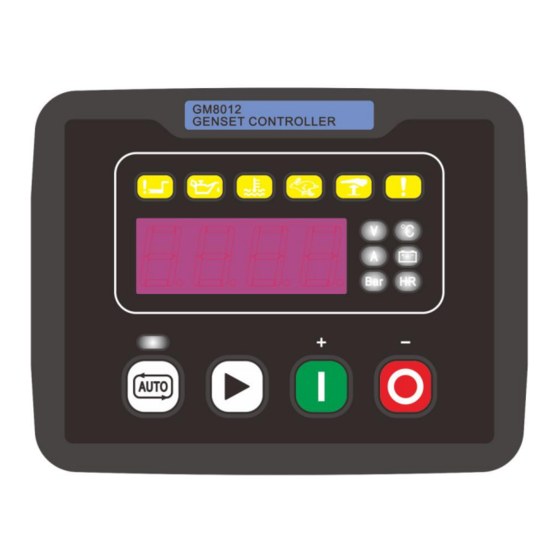
Manual THINICON TH101132ER1 Panel Operation The operation panel consists of 3 sections: 4-digit LED digital tube displays measurement parameters and operating status, common warning/fault indicator, operation buttons and control mode selection buttons The LED digital tube display and its control buttons provide the operator with a friendly operator interface that allows the operator to read information and set operating parameters. - Page 17 Manual THINICON TH101132ER1 High water temperature lamp When the controller has a high water temperature warning, the indicator light flashes. When the controller has a high water temperature shutdown fault, the indicator light is on. Overspeed light The indicator flashes when the controller has an overspeed warning.
-
Page 18: Control And Operation Instruction
Manual THINICON TH101132ER1 Control and Operation Instruction The controller has a variety of control mode, the operator panel can be set to automatic mode and the non-automatic mode. Non-automatic mode there are two kinds of situations, such as no definable switch is set to "activate the test mode", for the manual operation mode;... - Page 19 Manual THINICON TH101132ER1 4.2 AUTO Control Sequence The controller is running in ―AUTO‖ mode. Generator Auto Start Sequence: Generator in the standby mode, only in the following situations occur, generator start-up program began: Definable input port for the remote control load a definition.
- Page 20 Manual THINICON TH101132ER1 CAUTION: If the control system does not use the speed sensor, that is, the engine cut off the signal from the generator frequency, must ensure that the generator in the process of turning, the output voltage is greater than the controller measure the voltage to avoid damage to the motor.
- Page 21 Manual THINICON TH101132ER1 4.3 MAN control Sequence The controller is running in ―MANUAL‖ mode. Generator starting sequence: Pressing ―START‖ button the fuel relay action, and open the fuel solenoid of engine. After 300ms delay, the start relay closed output, the start motor engages and begins to crank, When the engine speed reaches the crank cutout RPM, the controller output is de-energised and the safety-on delay starts.
- Page 22 Manual THINICON TH101132ER1 4.4 Start and stop sequence of engine whose fuel solenoid is N.O.type: There are two kinds of fuel solenoids for an engine, one is N.C. type, the valve of this solenoid is closed when the engine is in standby and it can be opened by switching on power; another is N.O. type, the valve of this solenoid is opened when engine is in standby and it can be closed by switching on power.
- Page 23 Manual THINICON TH101132ER1 4.7 The function of forcing start: Reason to add this function to the controller is that when the engine under abnormal conditions, e.g. the battery voltage is too low or ambient temperature is too low, or generator only outputs voltage at a high speed when magnetic pick-up is not used, the Genset cannot be started successfully when it implements the build-up cranking process of controller.
-
Page 24: Measure And Display Data
Manual THINICON TH101132ER1 Measure and Display Data Gen 3 phase line voltage L1-L2 L2-L3 L3-L1 Gen frequency Hz (L1) Gen V (L1-N) Ph-N Gen current I1 Gen single-phase active power P1 Engine oil pressure Bar (signal from engine LOP sensor) Engine coolant temperature ℃(signal from engine HET sensor) -
Page 25: Pre-Alarm And Shutdown Alarm
Manual THINICON TH101132ER1 Pre-alarm and Shutdown Alarm Controller to configure different levels of alarm, according to actual application requirements for each limit beyond the protection function is triggered and control procedures to be configured, different grade configuration table is as follows:... -
Page 26: Parameters Setting
Manual THINICON TH101132ER1 Parameters Setting 7.1 SYSTEM Items Setting Range Preset Quit Password 0000 to 9999 Comm. address 1 to 247 Startup mode 0 Man/1 Auto/ 2 Last CT ratio 5:5 to 6000:5 1000:5 PT ratio 1.0:1 to 10.0:1 1.0:1... - Page 27 Manual THINICON TH101132ER1 Rated voltage For the definition of the power generation rated voltage. As a reference value for high / low voltage. Rated current Used to define the generator rated current. As a reference value for overcurrent limit.
- Page 28 Manual THINICON TH101132ER1 7.2 GENERATOR Parameter Setting range Preset Quit GEN V-monitor type 0 ph-ph/1 ph-n GEN-V under 1 Function 0 N/1 Y Limit 20 to 200% Delay 0 to 999s Delay by 0 to 3 ALM. class 0 to 6...
- Page 29 Manual THINICON TH101132ER1 GEN-Hz over 2 Function 0 N/1 Y Limit 10.0 to 500.0Hz 57.0Hz Delay 0 to 999s Delay by 0 to 3 ALM. class 0 to 6 2.10 GEN-I over 1 Function 0 N/1 Y Limit 50 to 300%...
- Page 30 In different voltage input type, select "phase - phase" or "phase - zero" , monitoring voltage is different, specifically in the following table: Parameter Ph - ph Ph - N Voltage type ,V ,V GM8010 - - - GM8011 - GM8012 -...
- Page 31 Manual THINICON TH101132ER1 GEN-V over 1&2 Controller provides two levels of high-voltage limit monitoring for users to choose for warning, fault shutdown and control. If you select 1/2/3 alarm level when the protection function triggered, LED digital tube displays "!W:GEN-V over 1" or "!W:GEN-V over 2"; if select 4/5/6 alarm level when protection function triggered, LED digital tube display ―!A:GEN-V over 1 "or"...
- Page 32 Manual THINICON TH101132ER1 GEN-Hz over 1&2 Controller provides two levels of high-frequency limit monitoring for users to choose for warning, fault shutdown and control. If you select 1/2/3 alarm level when the protection function triggered, LED digital tube displays "!W:GEN-Hz over 1" or "!W:GEN-Hz over 2"; if select 4/5/6 alarm level when protection function triggered, LED digital tube display‖...
- Page 33 Manual THINICON TH101132ER1 GEN-KW over 1&2 Controller provides two levels of overload monitoring for users to choose for warning, fault shutdown and control. If you select 1/2/3 alarm level when the protection function triggered, LED digital tube displays "!W:GEN-KW over 1" or "!W:GEN-KW over 2"; if select 4/5/6 alarm level when protection function triggered, LED digital tube displays ―!A:GEN-KW over 1 "or"!A:GEN-KW over 2".
- Page 34 Manual THINICON TH101132ER1 ENGINE Parameter Setting range Preset Quit Engine rated speed 99 to 9999RPM 1500 MPU input 0 N/1 Y Fly wheel teeth 5 to 300 Set pickup now Pair of poles 1 to 20 Fuel mode 0 N.C/1 N.O...
- Page 35 Manual THINICON TH101132ER1 3.27 Batt. Overvolt Function 0 N/1 Y Limit 1.0 to 40.0 V 35.0 V Delay 0 to 999s Delay by 0 to 3 ALM. class 0 to 6 3.28 Batt. Undervolt Function 0 N/1 Y 1.0 to 40.0 V Limit 8.0 V...
- Page 36 Manual THINICON TH101132ER1 Pair of poles Used to define the generator exciter poles. Controller speed measurement value from the frequency signal of the generator, for the measurement operation of speed. Fuel mode Used to define the type of fuel ( details refer to section 4.4).
- Page 37 Manual THINICON TH101132ER1 Pre-heat mode Used to configure the mode of preheat. There are 5 pre-heat modes for selection, please read the description of preheat function for details. Pre-heat time The warm-up duration before the engine starts to drive;...
- Page 38 Manual THINICON TH101132ER1 Overspeed level1&2 Controller provides two levels of overspeed monitoring for users to choose for warning, fault shutdown and control. If you select 1/2/3 alarm level when the protection function triggered, LED digital tube displays "!W:Overspeed level1" or "!W:Overspeed level2"; If you select 4/5/6 alarm level when protection function triggered, LED digital tube displays‖...
- Page 39 Manual THINICON TH101132ER1 Batt. overvolt The controller detects the battery voltage, and provide a high limit protection for users to choose for warning, fault shutdown and control. If you select 1/2/3 alarm level when the protection function triggered, LED digital tube displays "!W:Batt.Overvolt‖; If select 4/5/6 alarm level when protection function triggered, LED digital tube displays"...
- Page 40 Manual THINICON TH101132ER1 Analog INPUT Parameter Setting range Preset Quit P-sensor type 1 to 16 /not used Oil-P low level1 Function 0 N/1 Y Limit 0.0 to 150.0 Bar 1.4Bar Delay 0 to 999s Delay by 0 to 3 ALM. class...
- Page 41 Manual THINICON TH101132ER1 Menu descriptions: P-sensor type Used to define the type of pressure sensor. The controller built-in a variety of pressure sensor types to choose,as follow: Code Mode Note Not used Close for LOP Closed (low) is valid...
- Page 42 Manual THINICON TH101132ER1 Murphy 7 bar: P(Bar) P(PSI) 10.0 20.0 30.0 40.0 50.0 60.0 70.0 80.0 90.0 100.0 R(Ω) Pre-set 1: P(Bar) 10.0 P(PSI) 14.5 29.0 43.5 58.0 72.5 87.0 101.5 116.0 130.5 145.0 R(Ω) Pre-set 2: P(Bar) 10.0 P(PSI) 14.5...
- Page 43 Manual THINICON TH101132ER1 Oil-P low level 1&2 Controller provides two levels of low oil pressure limit monitoring for users to choose for warning, fault shutdown and control. If you select 1/2/3 alarm level when protection function triggered, LED digital tube displays "...
- Page 44 Manual THINICON TH101132ER1 The parameters appendix of HEP sensor: VDO 120℃: T(℃) T(℉) R(Ω) VDO 150℃: T(℃) T(℉) R(Ω) Datcon: T(℃) T(℉) R(Ω) Murphy: T(℃) T(℉) R(Ω) 1029 PT100: T(℃) -100 T(℉) -148 R(Ω) Pre-set 1: T(℃) T(℉) R(Ω) Pre-set 2:...
- Page 45 Manual THINICON TH101132ER1 NOTE: ―Configurable‖ means user can input the data manually according to the sensor curve. Configurable 1 only can be set through the software; configurable 2 or 3 can be done through the push buttons on the front panel or software.
- Page 46 Manual THINICON TH101132ER1 Discrete IN/OUT Parameter Setting range Preset Quit D-Input 1 Config 0 to 30 D-Input 2 Config 0 to 30 D-Input 3 Config 0 to 30 D-Input 4 Config 0 to 30 Relay 1 Config 0 to 120 Relay 1 logic 0 N.O /1 N.C...
- Page 47 Manual THINICON TH101132ER1 Menu descriptions: D-Input * Config Used to define the D-input function. The digital input is active when closed (low level); Defined the function of discrete input, controller built-in a variety of functions for user to Function choose, as follows "definable D-input function menu.
- Page 48 Manual THINICON TH101132ER1 Select this function of discrete input port connected to the GEN closed aux. GCB auxiliary contacts of power generation load switch, for monitoring the status of the closing or opening of the GCB. Select this function of discrete input port connected to the fuel...
- Page 49 Manual THINICON TH101132ER1 Select this function, the discrete input signal function is Start button equivalent to control panel "start" button, it provides users with a remote start buttons. When selecting this digital input signal of function is active, the Inhibit Genset controller can not issue a closing signal in any mode.
- Page 50 Manual THINICON TH101132ER1 Relay * Config Use to configure the relay function selection. Define the role of the relay output, controller built-in a variety of functions for the user Function to choose, as follows " configure relay output menu".
- Page 51 Manual THINICON TH101132ER1 Output relay action, after the generator closing failure GCB fail to close occurred . The crank attempts of engine reaches the setting have been not Fail to start successful ignition, the output relay action. The engine is still running after the end of the downtime Fail to stop timing set, the output relay action.
- Page 52 Manual THINICON TH101132ER1 When the generator frequency is lower than the setting GEN-Hz under1 of power generation of low-frequency level 1 while delay confirm, its action. When the generator frequency is lower than the setting GEN-Hz under2 of power generation of low-frequency level 2 while delay confirm, its action.
- Page 53 Manual THINICON TH101132ER1 Select this function of output relay, when the cooling temperature of engine is below the lower limit of preheat Heater control open level value of setting, its action, and keep until the cooling temperature higher than the high limit of the...
- Page 54 Manual THINICON TH101132ER1 CALIBRATION MENU Parameter Setting range Preset Quit GEN. V1 offset -9.9% to 9.9% GEN. V2 offset -9.9% to 9.9% GEN. V3 offset -9.9% to 9.9% Current I1 offset -9.9% to 9.9% Pressure offset -9.9% to 9.9% Temperature offset -9.9% to 9.9%...
-
Page 55: Installation Guide
Manual THINICON TH101132ER1 Installation Guide 8.1 The cutout dimensional drawing installed on panel as follows: Cutout dimension:98mm(W) x 77mm (H) . Dashed box dimensions for the controller.. The controller is fixed by 2 special fittings. NOTE: If the installation of the controller installed directly on the chassis of the generator or other violent vibration of the device, must be installed shock absorber. -
Page 56: Lcd Displays And Menu System
Fault status information. Example: GM8010 Operation Description Status display when no light is on Press ―... - Page 57 Manual THINICON TH101132ER1 Example:GM8011 Operation Description This page shows the power generation phase voltage L1 Press ― ‖ to switch the display interface This page shows the generator current I1 Press ― ‖ to switch the display interface This page shows the active power P1 Press ―...
- Page 58 Manual THINICON TH101132ER1 9.2 Setting running parameter Press and hold ― ‖ button 2sec to enter into settings menu, parameter setting modification is incremented or decremented bit by bit, then use ― ‖or― ‖ to scroll page in the same menu list, press ―...
- Page 59 Manual THINICON TH101132ER1 Example: (the parameters of the controller reverts to the factory default values) Operation Description Press and hold ― ‖ 2sec, enter into parameters settings menu, then LED displays Press ― ‖ button and then press ― ‖ 3 times, then LED displays: Press ―...
- Page 60 Manual THINICON TH101132ER1 9.3 Fault Code Table Name Code Name Code GEN-V under 1 Underspeed level 2 GEN-V under 2 Fail to start GEN-V over 1 Fail to stop GEN-V over 2 Batt. over volt GEN-Hz under 1 Batt. under volt...
-
Page 61: 10 Technical Specification
Manual THINICON TH101132ER1 10 Technical Specification 10.1 AC voltage: Type True RMS Phase voltage 15 to 346VAC Line voltage 25 to 600VAC <0.1W Max power wastage per line Accuracy Display 0 to 600KV 10.2 AC voltage frequency: Input frequency 3 to 500Hz(voltage≥15VAC)... - Page 62 Manual THINICON TH101132ER1 10.7 Analog Inputs Number 2 (Max) Sensor type Resistance Resolution 10 bits 0 to1 KΩ Range Accuracy 2% When full scale, except for sensor error 10.8 Speed sensor Voltage range 1 to 70V Max. frequency 10000Hz Fly wheel teeth 5 to 300 10.9 Environmental parameters...