
Related Manuals for Emerson Rosemount 1408A


Summary of Contents for Emerson Rosemount 1408A
- Page 1 Reference Manual 00809-0200-4480, Rev AA May 2021 ™ Rosemount 1408A Level and Flow Transmitter Non-Contacting Radar...
- Page 2 • 1-800-654-7768 (24 hours a day — includes Canada) • Outside of these areas, contact your local Emerson representative. WARNING Failure to follow safe installation and servicing guidelines could result in death or serious injury. Ensure the transmitter is installed by qualified personnel and in accordance with applicable code of practice.
-
Page 3: Table Of Contents
Reference Manual Contents 00809-0200-4480 May 2021 Contents Chapter 1 Introduction......................5 1.1 Using this manual........................5 1.2 Open source licenses........................5 1.3 Product recycling/disposal......................5 Chapter 2 Transmitter overview....................7 2.1 Measurement principle........................ 7 2.2 Process characteristics......................... 7 2.3 Vessel characteristics........................8 2.4 Application examples........................8 2.5 Components of the transmitter.................... - Page 4 B.8 Radio/EMC Republic of Korea.....................78 Appendix C Configuration parameters..................79 C.1 Menu tree..........................79 C.2 Basic setup..........................80 C.3 Digital output..........................81 C.4 Analog output........................... 83 C.5 Geometry..........................85 C.6 Volume flow..........................86 C.7 Advanced setup.........................87 Rosemount 1408A Level and Flow Transmitter...
-
Page 5: Chapter 1 Introduction
Open source licenses This device uses open source software. Further information can be found in the License Information Document available at Emerson.com/Rosemount. Product recycling/disposal Recycling of equipment and packaging should be taken into consideration and disposed of in accordance with local and national legislation or regulations. - Page 6 Introduction Reference Manual May 2021 00809-0200-4480 Rosemount 1408A Level and Flow Transmitter...
-
Page 7: Chapter 2 Transmitter Overview
A. Frequency (GHz) B. Time (s) C. Transmitted signal D. Reflected signal The Rosemount 1408A can also calculate the volume flow rate in an open channel. Process characteristics 2.2.1 Dielectric constant A key parameter for measurement performance is reflectivity. A high dielectric constant of the media provides better reflection and enables a longer measuring range. -
Page 8: Vessel Characteristics
The Rosemount 1408A uses Frequency Modulated Continuous Wave (FMCW) technology and smart algorithms to maximize measurement accuracy and reliability, even in small tanks and challenging fast-filling vessels. - Page 9 Open air applications Get reliable level measurements of sumps or ponds, regardless of challenging surface and weather conditions. Open channel flow Use the Rosemount 1408A for volume flow measurement of water and wastewater in open channels. Reference Manual...
-
Page 10: Components Of The Transmitter
Related information Dimensional drawings Easy integration with IO-Link The Rosemount 1408A provides both conventional 4-20 mA and digital switch outputs, enabled by IO-Link connectivity. This supports easy integration into any automation system. Each IO-Link system consists of an IO-Link master and one or more IO-Link devices (sensors and actuators). - Page 11 Reference Manual Transmitter overview 00809-0200-4480 May 2021 Figure 2-3: Example of an IO-Link System A. Industrial ethernet B. Programmable logic controller (PLC) C. Industrial Fieldbus D. IO-Link master E. IO-Link devices Reference Manual...
- Page 12 Transmitter overview Reference Manual May 2021 00809-0200-4480 Rosemount 1408A Level and Flow Transmitter...
-
Page 13: Chapter 3 Mechanical Installation
Reference Manual Mechanical installation 00809-0200-4480 May 2021 Mechanical installation Safety messages Instructions and procedures in this section may require special precautions to ensure the safety of the personnel performing the operations. Information that potentially raises safety issues is indicated by a warning symbol ( ). - Page 14 • Do not mount close to or above the inlet stream. • Multiple Rosemount 1408A transmitters can be used in the same tank without interfering with each other. Figure 3-1: Recommended Mounting Position 3.2.2 Free space requirements If the transmitter is mounted close to a wall or other tank obstruction such as heating coils and ladders, noise might appear in the measurement signal.
- Page 15 Reference Manual Mechanical installation 00809-0200-4480 May 2021 Table 3-1: Distance to Tank Wall (L) Minimum Recommended 8 in. (200 mm) ½ of tank radius 3.2.3 Inclination The transmitter should be mounted vertically to ensure a good echo from the product surface.
- Page 16 19.7 ft. (6 m) 2.8 ft. (0.8 m) 3.5 ft. (1.1 m) 26.2 ft. (8 m) 3.7 ft. (1.1 m) 4.6 ft. (1.4 m) 32.8 ft. (10 m) 4.7 ft. (1.4 m) 5.8 ft. (1.8 m) Rosemount 1408A Level and Flow Transmitter...
- Page 17 Reference Manual Mechanical installation 00809-0200-4480 May 2021 3.2.6 Nozzle requirements To allow the microwaves to propagate undisturbed, the nozzle dimensions should be kept within the specified limits as given in Table 3-3. The inside of the nozzle must be smooth (i.e.
-
Page 18: Mounting Preparations
Remove the protective cap The protective cap protects the PTFE sealing from impacts during transport and storage. Procedure Before installing, carefully remove the protective cap. Note Be careful not to scratch or otherwise damage the PTFE sealing. Rosemount 1408A Level and Flow Transmitter... -
Page 19: Mount Transmitter On Tank
Reference Manual Mechanical installation 00809-0200-4480 May 2021 Mount transmitter on tank 3.4.1 Bracket mounting Procedure 1. Mount the bracket on the wall/ceiling or other flat surface. 2. Apply lubricating paste on the transmitter thread. Note The paste must be approved for the application and compatible with the elastomers used. - Page 20 3. Tighten the bolts and nuts with sufficient torque for the flange and gasket choice. 0.75 in. (19 mm) 4. Apply lubricating paste on the transmitter thread. Note The paste must be approved for the application and compatible with the elastomers used. Rosemount 1408A Level and Flow Transmitter...
- Page 21 Reference Manual Mechanical installation 00809-0200-4480 May 2021 5. Mount the transmitter on the tank. Torque 310 in-lb (35 N-m) 39 mm Note Be careful not to scratch or otherwise damage the PTFE sealing. 3.4.3 Mount the threaded adapter version Procedure 1.
- Page 22 Mechanical installation Reference Manual May 2021 00809-0200-4480 4. Mount the transmitter on the tank. Torque 310 in-lb (35 N-m) 39 mm Note Be careful not to scratch or otherwise damage the PTFE sealing. Rosemount 1408A Level and Flow Transmitter...
- Page 23 Reference Manual Mechanical installation 00809-0200-4480 May 2021 3.4.4 Mount on a threaded connection Procedure 1. Apply lubricating paste on the transmitter thread. Note The paste must be approved for the application and compatible with the elastomers used. 2. Mount the transmitter on the tank. Torque 310 in-lb (35 N-m) 39 mm Note...
- Page 24 Mechanical installation Reference Manual May 2021 00809-0200-4480 Rosemount 1408A Level and Flow Transmitter...
-
Page 25: Chapter 4 Electrical Installation
Reference Manual Electrical installation 00809-0200-4480 May 2021 Electrical installation Safety messages Instructions and procedures in this section may require special precautions to ensure the safety of the personnel performing the operations. Information that potentially raises safety issues is indicated by a warning symbol ( ). - Page 26 OUT2 OUT1/IO-Link Table 4-1: Pin Assignment Wire color Signal Brown 24 V White OUT2 Digital output or active 4-20 mA analog output Blue Black OUT1/IO-Link Digital output or IO-Link mode According to IEC 60947-5-2. Rosemount 1408A Level and Flow Transmitter...
- Page 27 Reference Manual Electrical installation 00809-0200-4480 May 2021 Figure 4-2: Example Circuits 2: OUT2 4: OUT1 2: OUT2 4: OUT1 2: OUT2 4: OUT1 2: OUT2 4: OUT1 A. 2 x Digital output PnP B. 2 x Digital output NpN C. 1 x Digital output PnP / 1 x Analog output D.
-
Page 28: Power Up Transmitter
Power up transmitter Prerequisites Procedure Verify the power supply is disconnected. 2. Insert the M12 connector and screw tight. See the manufacturer’s instruction manual for recommended torque. 3. Connect the power supply. Related information Ingress protection Rosemount 1408A Level and Flow Transmitter... -
Page 29: Chapter 5 Configuration
Reference Manual Configuration 00809-0200-4480 May 2021 Configuration Safety messages Instructions and procedures in this section may require special precautions to ensure the safety of the personnel performing the operations. Information that potentially raises safety issues is indicated by a warning symbol ( ). -
Page 30: Connect The Transmitter To The Io-Link
Rosemount IO-Link Assistant Get the latest IODD files The Rosemount IO-Link Assistant software checks and lets you download the latest IODDs for your device catalog. Prerequisites For an online update, an internet connection is required. Rosemount 1408A Level and Flow Transmitter... - Page 31 An IODD DTM Interpreter is required to integrate IODDs into an FDT/DTM environment (e.g PACTware). Prerequisites The IODD DTM Interpreter is usually included in the FDT/DTM software installation package. It can also be downloaded from Emerson.com/Rosemount1408A. Procedure 1. Start the IODD DTM Interpreter software. Reference Manual...
- Page 32 3. Browse to the IODD file (.xml) and select Open. 4. Start the configuration tool and update the device catalog. Need help? If the new DTM is not added automatically at start-up, then select View → Device Catalog → Update Device Catalog. Rosemount 1408A Level and Flow Transmitter...
-
Page 33: Perform The Basic Setup
Reference Manual Configuration 00809-0200-4480 May 2021 Perform the basic setup 5.5.1 Set the engineering units Procedure 1. Under Menu, select Parameter → Basic Setup. 2. In the Engineering Units list, select Metric or Imperial. Option Description Metric Length: m Temperature: °C Volume flow: m Imperial Length: in. - Page 34 2. In the Volume Flow Calculation Method list, select the preferred method. Choose from: • Linearization table • Parshall flume • Khafagi-Venturi flume 3. Select Volume Flow Table/Formula, and then set the parameters as desired. 4. Select Write to device. Related information Volume flow Rosemount 1408A Level and Flow Transmitter...
-
Page 35: Operation And Maintenance
Reference Manual Operation and maintenance 00809-0200-4480 May 2021 Operation and maintenance Safety messages Instructions and procedures in this section may require special precautions to ensure the safety of the personnel performing the operations. Information that potentially raises safety issues is indicated by a warning symbol ( ). - Page 36 A value that triggers an alert, such as a high or low temperature indication, will change the overall status of the device, but the measurement might still be indicated as “Good” if the reliability of the data is good. Rosemount 1408A Level and Flow Transmitter...
-
Page 37: Enter The Demonstration Mode
Reference Manual Operation and maintenance 00809-0200-4480 May 2021 Enter the demonstration mode In this mode, the signal processing method is optimized for demo situations when simulating a product surface with, for example, a measurement target plate. Note This mode is intended for demonstration purposes only, and should not be used for normal operations. - Page 38 Operation and maintenance Reference Manual May 2021 00809-0200-4480 Rosemount 1408A Level and Flow Transmitter...
-
Page 39: Service And Troubleshooting
Reference Manual Service and troubleshooting 00809-0200-4480 May 2021 Service and troubleshooting Safety messages Instructions and procedures in this section may require special precautions to ensure the safety of the personnel performing the operations. Information that potentially raises safety issues is indicated by a warning symbol ( ). -
Page 40: Diagnostic Messages
The software has detected an internal error. Recommended actions 1. Restart the device. 2. Restore default settings and reconfigure the device. 3. If the condition persists, replace the device. Related information Perform a device reset Restore to factory settings Rosemount 1408A Level and Flow Transmitter... - Page 41 Reference Manual Service and troubleshooting 00809-0200-4480 May 2021 7.2.3 General power supply fault – Check availability Alarm classification Device status Failure Class Error Possible cause Power supply drops below 18 Vdc during transmitter start-up. Recommended actions Verify voltage is 18-30 Vdc at the transmitter terminal. 7.2.4 Parameter error –...
- Page 42 The device is in simulation mode and is not reporting actual information. Recommended actions 1. If this behavior is not desired, stop simulation mode. 2. If the condition persists, restart the device. Related information Use the simulation mode Perform a device reset Rosemount 1408A Level and Flow Transmitter...
- Page 43 Reference Manual Service and troubleshooting 00809-0200-4480 May 2021 7.2.7 Level measurement lost – Check application Alarm classification Device status Failure Class Error Possible cause No valid level reading. Reasons may be multiple: • No valid surface echo peak in the measuring range •...
- Page 44 Device status Out of specification Class Warning Possible cause The electronics temperature is outside the operating range. Recommended actions 1. Verify ambient temperature is within the operating range. 2. Insulate device. Related information Ambient temperature Rosemount 1408A Level and Flow Transmitter...
- Page 45 Reference Manual Service and troubleshooting 00809-0200-4480 May 2021 7.2.10 Short circuit – Check installation Alarm classification Device status Out of Specification Class Error Possible cause Short circuit on the digital output. Recommended actions Check cable and connections. 7.2.11 Primary supply voltage over-run – Check tolerance Alarm classification Device status Out of specification...
- Page 46 Frequent writing of parameters from master to device. Recommended actions 1. Check the master configuration. 2. Restart the device. 3. If error persists, contact your local Emerson representative. Related information Perform a device reset Rosemount 1408A Level and Flow Transmitter...
- Page 47 Reference Manual Service and troubleshooting 00809-0200-4480 May 2021 7.2.15 Measurement range over-run – Check application Alarm classification Device status Out of Specification Class Error Possible cause The level measurement is outside the configured range for the volume flow. Recommended actions Ensure that level values within operating range are included in the volume flow table.
-
Page 48: Troubleshooting Incorrect Level Readings
Reference Height). • Analyze the Echo Peaks and check General Threshold. • Restore default settings and reconfigure the device. Related information Reference height Analyze the echo peaks Adjust the general threshold Restore to factory settings Rosemount 1408A Level and Flow Transmitter... - Page 49 Reference Manual Service and troubleshooting 00809-0200-4480 May 2021 7.3.2 Level is stuck in measuring range Figure 7-2: Symptom A. Level B. Time C. Actual level D. Reported level Possible cause Disturbing object in the tank. Recommended actions • Analyze the Echo Peaks and check General Threshold. •...
- Page 50 Move the transmitter to another position. Possible cause Product build-up on the antenna. Recommended actions • Clean the antenna. Related information Analyze the echo peaks Adjust the general threshold Change the upper null zone Mounting position Rosemount 1408A Level and Flow Transmitter...
- Page 51 Reference Manual Service and troubleshooting 00809-0200-4480 May 2021 7.3.4 Level value drops when close to antenna Level value drops to a lower value when product surface is close to antenna. Figure 7-4: Symptom A. Level B. Time C. Actual level D.
- Page 52 Figure 7-5: Symptom A. Level B. Time C. Reported level Possible cause Excessive foaming or turbulence. Recommended actions • Under turbulent conditions with low level rates, consider increasing the Damping value. Related information Damping value Rosemount 1408A Level and Flow Transmitter...
- Page 53 Reference Manual Service and troubleshooting 00809-0200-4480 May 2021 7.3.6 Measured level is occasionally unstable Figure 7-6: Symptom A. Level B. Time C. Actual level D. Reported level Possible cause The product surface is close to a suppressed false echo. Recommended actions •...
- Page 54 D. Reported level Possible cause Damping value is set too high. Recommended actions • If there is a problem with lag during rapid level changes, consider decreasing the Damping value. Related information Damping value Rosemount 1408A Level and Flow Transmitter...
- Page 55 Reference Manual Service and troubleshooting 00809-0200-4480 May 2021 7.3.8 Incorrect level at 100% (20 mA) Symptom Measured level is correct at 0% (4 mA) but incorrect at 100% (20 mA). Figure 7-8: Symptom A. Level B. Time C. Actual level D.
- Page 56 B. Time C. Actual level D. Reported level Possible cause A strong double bounce echo is interpreted as the product surface. Recommended actions • Move the transmitter to another position. Related information Mounting position Rosemount 1408A Level and Flow Transmitter...
- Page 57 Reference Manual Service and troubleshooting 00809-0200-4480 May 2021 7.3.10 Dropping of level close to tank bottom Symptom Measured value drops to zero level in the tank bottom region. Figure 7-10: Symptom A. Level B. Time C. Actual level D. Reported level Possible cause Transmitter has locked on a strong tank bottom echo.
- Page 58 Recommended actions • Before opening the manway door, disconnect power to the transmitter. • After closing, restart the device. • Move the transmitter to another position. Related information Mounting position Perform a device reset Rosemount 1408A Level and Flow Transmitter...
-
Page 59: Managing Disturbance Echoes
Reference Manual Service and troubleshooting 00809-0200-4480 May 2021 7.3.12 Alarm mode close to tank bottom Symptom When the product surface is near the sloped tank bottom, the transmitter enters alarm mode. Figure 7-12: Symptom A. Level B. Time C. Actual level D. - Page 60 View the echo peaks to find out if there are disturbing echoes close to tank top. 2. Set the desired Upper Null Zone value. a) Under Menu, select Parameter → Geometry → Advanced. b) Enter the desired Upper Null Zone value. c) Select Write to device. Rosemount 1408A Level and Flow Transmitter...
-
Page 61: Service And Troubleshooting Tools
Reference Manual Service and troubleshooting 00809-0200-4480 May 2021 Figure 7-13: Upper Null Zone A. Upper Null Zone B. Disturbance echo C. 100% (20 mA) D. General threshold E. Product surface echo Related information Upper null zone Service and troubleshooting tools 7.5.1 Analyze the echo peaks Measurement problems can be understood by studying the position and amplitude of the... - Page 62 1. Under Menu, select Parameter → Service Tools → Simulation. 2. In the Simulated Level box, enter the desired value. This value will also be used for the volume flow calculation. 3. Select Write to device. 4. Select Start simulation (60 min). Rosemount 1408A Level and Flow Transmitter...
-
Page 63: Service Support
20±0.01 mA. 4. Select Exit Fixed Current Mode. Service support To expedite the return process outside of the United States, contact the nearest Emerson representative. Within the United States, call the Emerson Instrument and Valve Response Center using the 1-800-654-RSMT (7768) toll-free number. This center, available 24 hours a day, will assist you with any needed information or materials. - Page 64 Returned products must include a copy of the required Safety Data Sheet (SDS) for each substance. Emerson Instrument and Valve Response Center representatives will explain the additional information and procedures necessary to return goods exposed to hazardous substances.
-
Page 65: Appendix A Specifications And Reference Data
Reference Manual Specifications and reference data 00809-0200-4480 May 2021 Specifications and reference data Performance specifications A.1.1 General Reference conditions • Measurement target: Stationary metal plate, no disturbing objects • Temperature: 59 to 77 °F (15 to 25 °C) • Ambient pressure: 14 to 15 psi (960 to1060 mbar) •... - Page 66 • Radio Equipment Directive (2014/53/EU): ETSI EN 302 372 (without antenna extension), ETSI EN 302 729 (with antenna extension), and EN 62311 • Part 15 of the FCC Rules • Industry Canada RSS 211 Rosemount 1408A Level and Flow Transmitter...
-
Page 67: Functional Specifications
Reference Manual Specifications and reference data 00809-0200-4480 May 2021 Related information Product certifications Functional specifications A.2.1 General Field of application Continuous measurement of level and open channel flow. Minimum dielectric constant Measurement principle Frequency Modulated Continuous Wave (FMCW) Frequency range 77 to 81 GHz Maximum output power 3 dBm (2 mW) - Page 68 Maximum loop resistance is determined by the voltage level of the external power supply: Maximum Loop Resistance = 43.5 × (External Power Supply Voltage - 18) + 600 Ω Figure A-2: Load Limits 1200 1121 1100 1000 A. Loop Resistance (Ω) B. External Power Supply Voltage (Vdc) Rosemount 1408A Level and Flow Transmitter...
- Page 69 Reference Manual Specifications and reference data 00809-0200-4480 May 2021 Analog signal on alarm The transmitter automatically and continuously performs self-diagnostic routines. If a failure or a measurement error is detected, the analog signal will be driven offscale to alert the user. High or low failure mode is user-configurable. Table A-1: Signal on Alarm Level Custom levels...
- Page 70 Signal strength Volume flow calculations • Linearization table • Parshall flume • Khafagi-Venturi flume A.2.7 Process pressure -15 to 116 psig (-1 to 8 bar) Atmospheric pressure at temperatures below -4 °F (-20 °C) Rosemount 1408A Level and Flow Transmitter...
-
Page 71: Physical Specifications
Emerson is not in a position to evaluate or guarantee the compatibility of the process fluid or other process parameters with the product, options, configuration or materials of construction selected. - Page 72 Material exposed to tank atmosphere • PTFE sealing: PTFE fluoropolymer • O-ring: FVMQ • G1 thread: 316L (EN 1.4404) • Profile ring: FKM IP68 at 9.8 ft. (3 m) for more than 30 minutes. Rosemount 1408A Level and Flow Transmitter...
-
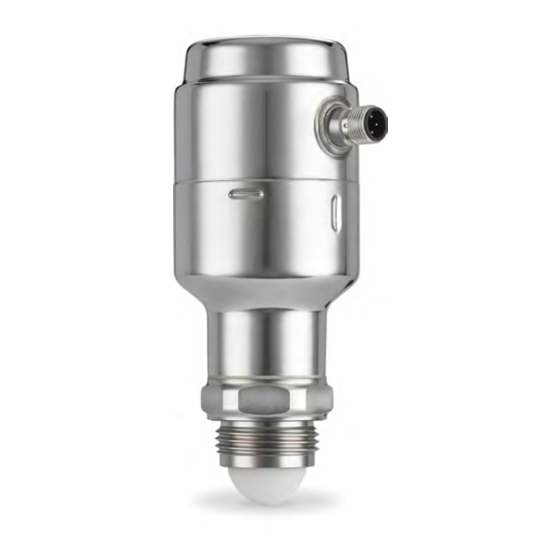
Page 73: Dimensional Drawings
Reference Manual Specifications and reference data 00809-0200-4480 May 2021 Dimensional drawings Figure A-4: Rosemount 1408A Ø 2.32 (59) 2.99 (76) 5.79 4.76 (147) (121) A. ISO 228/1-G1 thread B. M12 connector (A-coded) Dimensions are in inches (millimeters). Reference Manual... - Page 74 A. Antenna extension for open air installations Dimensions are in inches (millimeters). A.4.1 Bracket hole pattern Figure A-6: Hole Pattern 0.28 (7) 0.43 (11) 1.97 (50) Ø 0.28 (7) 30° Dimensions are in inches (millimeters). Rosemount 1408A Level and Flow Transmitter...
-
Page 75: Appendix B Product Certifications
1310. Telecommunication compliance Rosemount 1408A, with the antenna extension fitted, is a device for measurement of level in the open air or in an enclosure. When used for measurement in an enclosure (i.e metallic or reinforced concrete or fiberglass tanks, or similar enclosure structures made of comparable attenuating material), the antenna extension may be omitted. -
Page 76: Fcc
Okanagan Valley, British Columbia,) the installer/user must coordinate with, and obtain the written concurrence of, the Director of the DRAO before the equipment can be installed or operated. The Director of the DRAO may be contacted at Rosemount 1408A Level and Flow Transmitter... -
Page 77: Radio Equipment Directive (Red) 2014/53/Eu And Radio Equipment Regulations S.i. 2017/1206
Radio Equipment Regulations S.I. 2017/1206 Open air installations Rosemount 1408A, when fitted with the antenna extension, complies with ETSI EN 302 729 and EN 62311. Install at a separation distance of >4 km from Radio Astronomy sites, unless a special authorization has been provided by the responsible National regulatory authority (a list of Radio Astronomy sites may be found at www.craf.eu). -
Page 78: Radio/Emc Republic Of Korea
May 2021 00809-0200-4480 Closed tanks Rosemount 1408A without the antenna extension complies with ETSI EN 302 372 and EN 62311. The device must be installed in closed tanks (metal, reinforced concrete tanks or similar enclosure structures made of comparable attenuating material). Install according to requirements in ETSI EN 302 372 (Annex E). -
Page 79: Appendix C Configuration Parameters
Reference Manual Configuration parameters 00809-0200-4480 May 2021 Configuration parameters Menu tree Figure C-1: Parameter Menu > Parameter Basic Setup Engineering Units Reference Height Digital Outputs P-n Write Protection OUT1 Digital Output OUT1 Configuration DO Control Variable Alarm Configuration Alarm On/Off Delay Set Point Configuration High Alarm SP1-High Alarm Set Point... -
Page 80: Basic Setup
D. 0.6 in. (15 mm) Ensure the Reference Height is set as accurate as possible. The transmitter measures the distance to the product surface and subtracts this value from the Reference Height to determine the level. Rosemount 1408A Level and Flow Transmitter... -
Page 81: Digital Output
Reference Manual Configuration parameters 00809-0200-4480 May 2021 Related information Enter the reference height C.2.3 Digital output P-n The output polarity for the switching outputs (PnP or nPn). C.2.4 Write protection The transmitter can be software write protected to prevent unintentional configuration changes. - Page 82 Lost surface A. Level B. Time C. SP1 - High alarm set point D. Alarm on delay E. Lost surface (invalid level) C.3.3 Set point configuration High alarm Enable or disable the high alarm. Rosemount 1408A Level and Flow Transmitter...
-
Page 83: Analog Output
Reference Manual Configuration parameters 00809-0200-4480 May 2021 Low alarm Enable or disable the low alarm. Alarm set points SP1 - High alarm set point If the measured value is above this set point, the digital output is set to alarm state. SP2 - Low alarm set point If the measured value is below this set point, the digital output is set to alarm state. - Page 84 The high/low alarm current for the analog output when the device enters the alarm mode. Related information Analog signal on alarm High/low saturation value The device will continue to set a current that corresponds with the measurement until reaching the upper/lower limit (and then freeze). Rosemount 1408A Level and Flow Transmitter...
-
Page 85: Geometry
Reference Manual Configuration parameters 00809-0200-4480 May 2021 Related information Analog saturation levels Geometry C.5.1 Advanced Calibration offset Difference between surface distance measured by transmitter and the same distance measured by, for example, hand-dipping with a measurement tape. A positive Calibration Offset value will increase the presented level value. -
Page 86: Volume Flow
Volume flow calculation method Select the preferred volume flow calculation method. The are three options to choose from: • Linearization table • Parshall flume • Khafagi-Venturi flume Related information Set up the volume flow measurement Rosemount 1408A Level and Flow Transmitter... -
Page 87: Advanced Setup
Reference Manual Configuration parameters 00809-0200-4480 May 2021 C.6.2 Volume flow table The volume flow table is used to convert the measured level into a volume flow rate. Up to 30 level-volume flow pairs can be entered. C.6.3 Volume flow formula Table C-2: Parshall Flume Parameters Parameter Description... - Page 88 Configuration parameters Reference Manual May 2021 00809-0200-4480 Figure C-8: Threshold Principle A. General threshold B. Product surface echo Related information Adjust the general threshold Rosemount 1408A Level and Flow Transmitter...
- Page 89 Reference Manual 00809-0200-4480 May 2021 Reference Manual...
- Page 90 2021 Emerson. All rights reserved. Emerson Terms and Conditions of Sale are available upon request. The Emerson logo is a trademark and service mark of Emerson Electric Co. Rosemount is a mark of one of the Emerson family of companies. All other marks are the property...