
Related Manuals for Tecumseh F31HC

Summary of Contents for Tecumseh F31HC
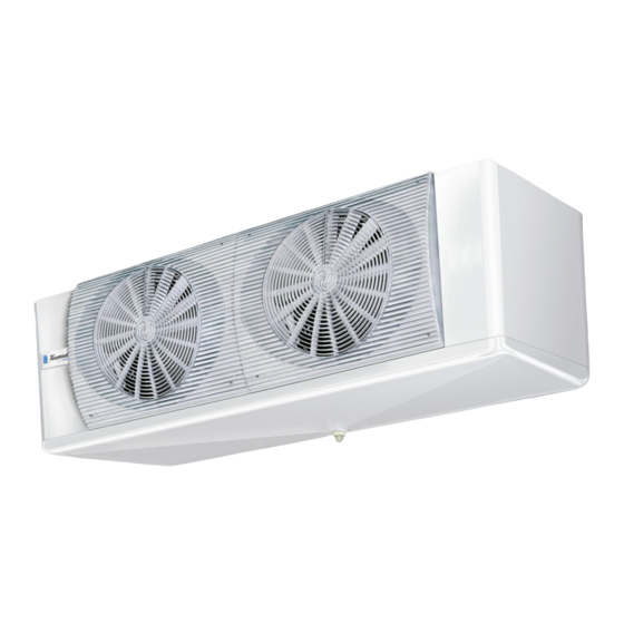
- Page 1 Model Series ENGLISH F31HC / F35HC Installation, Operation, Service Maintenance Instructions “UNIT COOLERS FOR COLD ROOMS” UNIT FOR USE WITH WALK-IN COOLER, FREEZER OR REFRIGERATED WAREHOUSE...
-
Page 2: Table Of Contents
INSTALLATION AND OPERATION MANUAL TABLE OF CONTENTS SUBJECT PAGE # Warning Symbols And Placards General Safety Information Product Warranty Statement Receiving And Inspection Uncrating And Rigging 5 - 6 Unit Mounting 6 - 8 Locating Equipment Drain Line Piping 8 - 9 Refrigerant Piping Refrigerant Piping (Distributor / TXV / Solenoid Valve) Leak Testing, Evacuation And Charging... -
Page 3: Warning Symbols And Placards
WARNING SYMBOLS AND THEIR MEANING Hand Injury Pos- Forklift Traffic Electricity Toxic Substan- sible Hot Surfaces Automatic Start Overhead Load Sharp Element MANDATORY SIGNS AND THEIR MEANING Hand Protection Eye Protection Ear Protection Check Guard Required Required Required Protective Clo- Use Safety Connect To Earth Hard Hat Area... -
Page 4: General Safety Information
EC fan and motor assemblies are not designed for replacement or servicing of individual parts. Replace only as a complete assembly. Tecumseh designed by LU-VE products are manufactured using the following primary materials; - Plastic Material; Polyethylene, ABS, Rubber - Ferrous Materials; Iron, Stainless Steel, Copper, Aluminum (possibly coated / treated for corrosion protection) ... -
Page 5: Product Warranty Statement
For more information please contact your local Tecumseh Sales representative or Corporate office at: Tecumseh Products Company / 5683 Hines Drive / Ann Arbor, MI 48108 / Ph. 734.585.9500 / www.tecumseh.com RECEIVING AND INSPECTION... -
Page 6: Unit Mounting
F35HC Fig. 2 14.8 Fig. 2 14.8 0.39 Fig. 5 F31HC 375 (14.8) Fig. 4 375 (14.8) Check coil pressure with an (0.39 accurate service gauge. If pressure is “low” or “0” the unit must be checked for leaks before installation. - Page 7 RECOMMENDED UNIT COOLER PLACEMENT Air flow within the refrigerated space is critical to achieving optimum cooling and freezing results. If air flow is compromised for any reason the unit may not provide satisfactory cooling performance. There are many potential reasons for poor air flow - few of which are the result of inadequate system capacity or unit malfunction.
- Page 8 UNIT MOUNTING DETAIL Units should be mounted flush to a level ceiling panel using 3/8” stainless steel bolts, hangar rods or lag screws. There is no need to block or pitch the unit to ensure proper condensate drainage if the unit is mounted level. NSF SANITATION Seal the gap between the top of the unit and the ceiling with NSF approved sealant to prevent accumulation of dirt and foreign material.
-
Page 9: Drain Line Piping
CONDENSATE DRAIN LINES It is the installers responsibility to ensure that all drain line piping is installed in accordance with local and national plumbing codes. Drain line piping runs should be kept as short as possible within the conditioned space whenever possible. ... -
Page 10: Refrigerant Piping
REFRIGERANT PIPING Use only clean, sealed ACR grade copper tubing for refrigerant duty. Unit warranty cover- age may be voided if system is installed with any other type of tubing. All piping must be CAUTION! UNIT IS PRESSURIZED installed according to local and national codes as well as accepted commercial refrigeration WITH DRY AIR OR INERT GAS FOR SHIPPING industry standards and practices. -
Page 11: Refrigerant Piping (Distributor / Txv / Solenoid Valve)
REFRIGERANT PIPING — CONTINUED All F31HC and F35HC model series unit coolers are equipped with a venturi-flo refrigerant distributor which ensures maximum efficiency of the coil under most all operating conditions. There is no orifice or nozzle plate to select / install in the distributor inlet. For optimum coil performance the TXV should be mounted within the end compartment of the unit and as short a distance as possible from the dis- tributor inlet. -
Page 12: Leak Testing, Evacuation And Charging
LEAK TESTING Once all field piping connections have been made and the braze joints visually inspected for any obvious voids or gaps introduce a trace amount of the system refrigerant through a service gauge manifold to achieve an equalized, static pressure of 25 to 30 PSIG. Make sure that all service and shut off valves are in the open position and slowly introduce a regulated, inert gas such as nitrogen to increase the static system pressure to approx. -
Page 13: Refrigerant Blends / Temperature Glide
REFRIGERANT BLENDS — TEMPERATURE GLIDE The majority of HFC refrigerants in use today are referred to as refrigerant “blends” (composed of two or more different refrigerants). As such, each component within this “blend” evaporates (or condenses) at different temperatures. The temperature range within which each of these different refrigerants completely changes state from a liquid to a gas (or vice versa) is referred to as “temperature glide”. -
Page 14: Typical Field Wiring Diagrams
FIELD WIRING DIAGRAMS — TYPICAL AIR DEFROST — 115/1/60 OR 208/230/1/60 UNIT COOLER IMPORTANT WIRING NOTES - INSTALLER PLEASE READ CAREFULLY! Sub-circuit fusing or service disconnect switches are not shown but may be required as per the NEC and / or local codes. It is the responsibility of the installing contractor to interpret and comply with all applicable electrical codes. - Page 15 FIELD WIRING DIAGRAMS — TYPICAL ELECTRIC DEFROST — 208/230/1/60 — (1) UNIT COOLER (TIMER ONLY) IIMPORTANT WIRING NOTES - INSTALLER PLEASE READ CAREFULLY! Sub-circuit fusing or service disconnect switches are not shown but may be required as per the NEC and / or local codes. It is the responsibility of the installing contractor to interpret and comply with all applicable electrical codes.
- Page 16 FIELD WIRING DIAGRAMS — TYPICAL ELECTRIC DEFROST — 208/230/1/60 — (1) UNIT COOLER WITH HEATER CONTACTOR IMPORTANT WIRING NOTES - INSTALLER PLEASE READ CAREFULLY! Sub-circuit fusing or service disconnect switches are not shown but may be required as per the NEC and / or local codes. It is the responsibility of the installing contractor to interpret and comply with all applicable electrical codes.
- Page 17 FIELD WIRING DIAGRAMS — TYPICAL ELECTRIC DEFROST — 208/230/1/60 — (2) UNIT COOLERS / TIMER ONLY IMPORTANT WIRING NOTES - INSTALLER PLEASE READ CAREFULLY! Sub-circuit fusing or service disconnect switches are not shown but may be required as per the NEC and / or local codes. It is the responsibility of the installing contractor to interpret and comply with all applicable electrical codes.
- Page 18 FIELD WIRING DIAGRAMS — TYPICAL ELECTRIC DEFROST — 208/230/1/60 — (2) UNIT COOLERS / (1) HEATER CONTACTOR IMPORTANT WIRING NOTES - INSTALLER PLEASE READ CAREFULLY! Sub-circuit fusing or service disconnect switches are not shown but may be required as per the NEC and / or local codes. It is the responsibility of the installing contractor to interpret and comply with all applicable electrical codes.
- Page 19 FIELD WIRING DIAGRAMS — TYPICAL ELECTRIC DEFROST — 208/230/3/60 — (1) UNIT COOLER WITH HEATER CONTACTOR IMPORTANT WIRING NOTES - INSTALLER PLEASE READ CAREFULLY! Sub-circuit fusing or service disconnect switches are not shown but may be required as per the NEC and / or local codes. It is the responsibility of the installing contractor to interpret and comply with all applicable electrical codes.
- Page 20 FIELD WIRING DIAGRAMS — TYPICAL ELECTRIC DEFROST — 208/230/3/60 — (2) UNIT COOLERS / (1) HEATER CONTACTOR IMPORTANT WIRING NOTES - INSTALLER PLEASE READ CAREFULLY! Sub-circuit fusing or service disconnect switches are not shown but may be required as per the NEC and / or local codes. It is the responsibility of the installing contractor to interpret and comply with all applicable electrical codes.
- Page 21 FIELD WIRING DIAGRAMS — TYPICAL ELECTRIC DEFROST — 208/230/3/60 — (2) UNIT COOLERS / (2) HEATER CONTACTORS IMPORTANT WIRING NOTES - INSTALLER PLEASE READ CAREFULLY! Sub-circuit fusing or service disconnect switches are not shown but may be required as per the NEC and / or local codes. It is the responsibility of the installing contractor to interpret and comply with all applicable electrical codes.
- Page 22 FIELD WIRING DIAGRAMS — OPTIONSs TWO SPEED FAN MOTOR RELAY WIRING OPTION Installing this relay will allow the unit cooler fans to operate at low speed whenever the room thermostat is satisfied or the unit is in defrost (when optional, off-cycle “air” defrost timer is used), resulting in reduced operating costs over the life of the equipment.
-
Page 23: Start Up
IMPORTANT NOTES AND INFORMATION Tecumseh designed by LU-VE unit coolers are designed to operate with the following commonly used refrigerants; R-404A, R-507, R-134A; R-407A, R-407C, R-407F, R-448A and R-449A For field retrofit applications it is also generally acceptable to use R-438A, R-449B or similar field service replacement refrigerants which have been designed to closely match the operating characteristics of the original refrigerant they replace. -
Page 24: Service - Maintenance (Fan / Motor Assy)
SERVICE — MAINTENANCE TROUBLESHOOTING EC MOTOR AND FAN ASSEMBLY Observation Possible Cause Corrective Action Fan Motor Rocks Back And Normal pre-start alignment for EC motor Not Applicable Forth No power to unit Check breaker or incoming power from defrost timer (check voltage at power term block) Bad connection at motor lead plug or terminal Repair / replace burned, damaged or... -
Page 25: Service - Maintenance (Defrost Cycle / Heaters)
SERVICE — MAINTENANCE TROUBLESHOOTING DEFROST CYCLE AND DEFROST HEATERS Observation Possible Cause Corrective Action Relocate unit away from doors / other openings Seal / repair all sources of air leaks into walk-in box Excessive moisture infiltration into cool- er / freezer (fan guard, motor / fan assem- Install strip curtains on access doors bly, unit housing, wall / ceiling panels may Limit door openings / close door when entering / exiting walk-in... -
Page 26: Remove / Replace Fan And Motor Assy
Note: In some cases more than (1) power source (breaker or service disconnect switch) may be supplied. BE SURE TO LOCK OUT / TAG OUT ALL SOURCES OF POWER! MODEL SERIES F35HC — MOTOR / FAN ASSEMBLY REMOVAL MODEL SERIES F31HC — MOTOR AND FAN ASSEMBLY REMOVAL... -
Page 27: Remove / Replace Defrost Heaters
SERVICE — MAINTENANCE IMPORTANT! Before any service / maintenance operations are performed to the unit, locate and lock out the main power supply to the unit. Note: In some cases more than (1) power source (breaker or service disconnect switch) may be supplied. BE SURE TO LOCK OUT / TAG OUT ALL SOURCES OF POWER! COIL AND DRAIN PAN HEATER REPLACEMENT PROCEDURE 1. -
Page 28: Start Up / Service / Maintenance Notes
START UP — SERVICE — MAINTENANCE NOTES... -
Page 29: Factory Contact Information
Customer Service Number: 888-254-1033 Customer Service Email: customer.service@tecumseh.com...