
Related Manuals for Dimplex PLXE Series


Summary of Contents for Dimplex PLXE Series
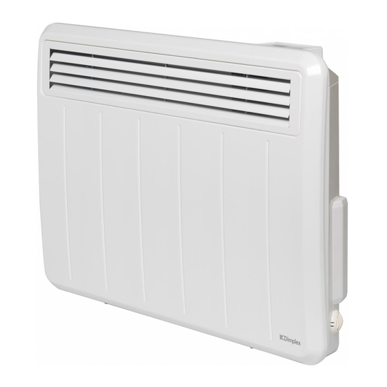
- Page 1 INSTRUCTION MANUAL Installation and Operating PLXE Panel Heater Models: PLX050E / PLX075E / PLX100E / PLX125E / PLX150E / PLX200E / PLXC300E *Note: PLXC300E features a slotted grille 08/54284/0 ISSUE: 1 Series: B...
- Page 2 IMPORTANT THESE INSTRUCTIONS SHOULD BE READ CAREFULLY AND RETAINED FOR FUTURE REFERENCE. Note also the information presented on the appliance IMPORTANT SAFETY ADVICE When using electrical appliances, basic precautions should always be followed to reduce the risk of fire, electrical shock, and injury to persons, including the following: IMPORTANT: The wall bracket supplied with the appliance must be used.
- Page 3 Note that due care and consideration must be taken when using this heater in series with a thermal control, a program controller, a timer or any other device that switches on the heat automatically, since a fire risk exists when the heater is accidentally covered or displaced.
- Page 4 Supplementary Earth Bonding Should Equipotential Earth Bonding be required the earthing conductor in the supply cord is deemed to provide the supplementary bonding connection (see Regulation 544.2.5, 17th Edition I.E.E. Wiring Regulations). Please note that lit cigarettes, candles and oil burners, combined with the convection effect of electric heaters can cause soot deposits to build up on the surface directly above and to the sides of the heater.
-
Page 6: Technical Details
With adaptive start control Contact details Glen Dimplex Heating and Ventilation Millbrook House, Grange Drive, Hedge End, Southampton, SO30 2DF Tel: 0344 879 3588 This product meets the Ecodesign requirements for an electric storage local space heater. Commission Regulation (EU) 2015/1188. - Page 7 Class I, with earth wire Colour / Finish Metal Chassis, Air Outlet Grille & Control Moulding - Traffic White (RAL 9016) Approvals CE, BEAB Guarantee 2 years Country of Origin United Kingdom Glen Dimplex Heating & Ventilation Manufacturer (GDC Group Ltd.)
-
Page 8: Wall Mounting
General The heater is designed for wall mounting using the wall bracket supplied. It should only be operated when in the upright position as shown - see Fig. 1 and Fig. 2. All models are splash proof to IP24. Before connecting the heater check that the supply voltage is the same as that stated on the heater. - Page 9 To mount the heater to the wall: 1. Remove wall mounting bracket from the back of the heater by depressing the spring latch at the side of each bracket - see Fig.2. 2. Fix the wall bracket securely to the wall through the four screw holes. Ensure only screw fittings provided are used for the particular wall type.
-
Page 10: First Time Power-On
First Time Power-On A setup wizard will display when the product is powered on for Important the first time. This will set the following: During initial heat-up, some odour may be emitted due to the newness of materials • Time, Date, Daylight Savings Time used in manufacture. - Page 11 This product is Dimplex Control capable * **. Control and monitor your heating and hot water with Dimplex Control. Group heaters into zones to easily control and track their energy usage. Any time. Anywhere. Search for Dimplex Control on your device’s app store.
-
Page 12: Operation
Operation WARNING: FAILURE TO FOLLOW THESE OPERATING INSTRUCTIONS MAY RESULT IN INJURY AND/OR DAMAGE. The controls are located on top of the heater consisting of a display screen and six touch sensitive buttons. Display Screen ‘Menu’ Button Out All Day ‘Back’... - Page 13 The heater controls can be easily adjusted by using the six buttons on the User Interface. 1. The Home Screen shows the options available at each stage of adjustment. Here the current target room temperature is displayed along with the User Timer mode of operation.
-
Page 14: Timer Modes
Timer Modes Timer Modes offer the most efficient mode of operation for a predictable heat demand. Additional functions such as Advance and Boost allow the User to make temporary adjustments to timer schedules for a more flexible operation. Each timer is broken down into 4 definable ‘Heating On’ time periods and temperatures per day, for each day of the week. - Page 15 Available Timer Modes To choose a timer mode, press Menu from the home screen. Use the Up / Down keys to highlight ‘Mode’, then press Enter to select. ‘Timer Mode’ should be highlighted. Press Enter to select. Manual Main Menu Mode ADVANCE ADVANCE...
-
Page 16: Copy And Paste
Modifying a Timer Mode Each timer is broken down into 4 definable ‘Heating On’ periods NOTE: and temperatures per day. Once modified a Timer Mode must be selected if you want to When Modify is chosen, ‘Heating On’ period 1 of 4 for the current begin using it. -
Page 17: Away Mode
The ‘Advance’ Function The Advance button is only used when a Timer Mode is active and allows the timer schedule to be changed temporarily. This button allows a ‘Heating On’ period to begin or end early. This is useful if you are at home when you had not planned to be, or need to leave when you had planned to have the heating on. - Page 18 Return Return Timer Mode ADVANCE Date/Time ADVANCE Date/Time ADVANCE User Timer MENU MENU MENU Saturday Home All Day 31-2-18 BACK BACK BACK Out All Day 07:00 ENTER ENTER ENTER Away ° Away Set Away NOTE: ADVANCE ° MENU The Back button can be used to end the Away Mode countdown BACK early.
-
Page 19: Boost Mode
Boost Mode Boost can be activated at any time, when the product is set to any Timer or Continuous heat mode; even if Advance is active, this mode will provide a temporary ‘Boost’ of heat. For settings, see Boost settings on Page 22. Boost Mode can be activated from the Home Screen by pressing Menu to access the Main Menu, then pressing Enter to select ‘Boost’. - Page 20 Product Locks Product Locks are methods of locking the heater’s controller to restrict access to functions. This can be activated and configured via the Settings Menu. When Product Lock is activated, the heater continues to run in whichever mode is currently active and any/all wireless communications remain active if enabled. Child Lock This is the simplest locking method and does not utilise a PIN code.
- Page 21 ‘Advance Function’ Operation during PIN Lock If Advance has been enabled during PIN Lock, the Advance button will remain active when PIN Lock is active. This will function in the same way it would if the controls were not locked: only if the Heater is Locked into a Timer Mode. •...
- Page 22 Settings To navigate to the settings menu, from the home screen: Main Menu Settings ADVANCE Heater Lock Boost MENU Boost Press the Menu button to access the Main Menu. Use the Setback Modes BACK Up / Down buttons to highlight ‘Settings’, then press the Date / Time ENTER Sound...
- Page 23 Boost Settings Default Boost Target Temperature This is the default Boost Target Temperature that is used when ‘Boost Mode’ is activated. Defined as a temperature value, this must be within the Heater’s Target Temperature Range. If the Target Temperature Range settings are changed then the Default Boost Temperature Range will be automatically changed to the closest valid temperature within Target Temperature Range.
- Page 24 Adaptive Settings Open Window Detection This is a global setting that can interrupt any active mode. Activating this setting enables Open Window Detection to switch the Heater to a ‘Heating Off’ state if it detects an open window in the room it’s operating Adaptive Start Adaptive Start is predictive function that only modifies Timer Mode operation.
-
Page 25: Advanced Settings
Advanced Settings These settings can be used to significantly change the operation of the heater. While useful for very specific requirements, there is a much higher risk of User error and unintended consequences of changing these settings compared to the top-level settings menu. It is recommended that these settings are only modified by trained professionals. -
Page 26: Error Codes
Error Codes Error codes are to be defined as a list. Each error code must be defined as a parameter that Central Control can read. Fault Code Description Component thermistor hardware fault Component overheat Internal serial comms error Heating element fault Open window detected Heat output disabled Time loss error... -
Page 28: Maintenance
Maintenance IMPORTANT: Before replacing the battery ensure the heater is isolated from the electricity supply. NOTE: Battery should be disposed of in an appropriate manner his product is fitted with a replaceable battery in the controls. To replace the battery, follow the steps below. 1. - Page 29 RF Module Installation 1. Unhinge the heater from the wall using the clips shown in Fig. 2 (page 7) and locate the battery module, indicated in Fig. 5 2. Slide the catch and pull module from the controls (See Fig 5; 1-3). 3.
- Page 30 For ROI please email serviceireland@glendimplex.com or call +353(0)1 842 833. We will need details of your Dimplex product, its serial number and a description of the fault which has occurred. You can find the model number and serial number for your Dimplex product on the heaters side. Once we receive your information and proof of purchase we will contact you to make the necessary arrangements.
- Page 31 • You must provide to Dimplex or its authorised agents on request the original receipt as proof of purchase and - if required by Dimplex - proof of delivery. If you are unable to provide this documentation, you will be required to pay for any repair work required.
- Page 32 Glen Dimplex Heating and Ventilation Millbrook House, Grange Drive, Hedge End, Southampton, SO30 2DF © Glen Dimplex. All rights reserved. Material contained in this publication may not be reproduced in whole or in part, without prior permission in writing of Glen Dimplex This product complies with the European Safety Standards EN60335-2-30 and the European Standard Electromagnetic Compatibility (EMC) EN55014, EN60555-2 and EN60555-3.