Table of Contents
Advertisement
Quick Links
Advertisement
Table of Contents
Troubleshooting

Related Manuals for Denso MOVINCOOL Climate pro k18


Summary of Contents for Denso MOVINCOOL Climate pro k18
- Page 1 SERVICE MANUAL CLIMATE PRO K18...
-
Page 2: Serial Number Location
SERIAL NUMBER LOCATION 00 0000 Month Year Sequential Model number name © 2020 DENSO PRODUCTS AND SERVICES AMERICAS, INC. All rights reserved. MovinCool® and Climate Pro® are registered trademarks of DENSO Corporation. -
Page 3: Table Of Contents
TABLE OF CONTENTS SERIAL NUMBER LOCATION ································································2 SAFETY PRECAUTIONS ········································································5 CONSTRUCTION ···················································································7 Dimensions ········································································································· 7 Names of Parts ·································································································· 8 Internal Structure ······························································································ 9 SPECIFICATIONS ················································································· 10 Technical Specifications ···················································································10 Characteristics ··································································································12 SERVICE INFORMATION ····································································· 13 Machine Status ·································································································13 Machine Records ······························································································14 TROUBLESHOOTING ··········································································... - Page 4 TABLE OF CONTENTS INSPECTION OF PARTS ······································································ 40 Capacitor ··········································································································40 Drain Switch ·····································································································40 Fan Motor ··········································································································41 Compressor ······································································································ 42 Thermistor ········································································································ 43 REFRIGERATION SYSTEM REPAIR ····················································· 44 Brazing ··············································································································44 Replacement of Refrigeration Cycle Parts ···················································46 Charging the System with R-410A Refrigerant ············································48 REASSEMBLY ·····················································································52 Wiring Diagram ································································································...
-
Page 5: Safety Precautions
SAFETY PRECAUTIONS To reduce the risk of injury or malfunction, read “Safety Precautions” carefully before servicing the unit. The seriousness is classified by the following indicators. Indicates a hazardous situation which, if not avoided, could WARNING result in death or serious injury. Indicates a hazardous situation which, if not avoided, could CAUTION result in minor or moderate injury, damage to the unit or its... - Page 6 WARNING Maintain the temperature of the refrigerant container below 104 °F (40 °C). Failure to do so may lead to explosion or fire. Brazing must be performed by a qualified technician only. Failure to do so may lead to fire, burns, injury or malfunction. When brazing, always wear eye protection and gloves.
-
Page 7: Construction
CONSTRUCTION Dimensions DIA. 11.8 27.4 22.1 Unit: inch... -
Page 8: Names Of Parts
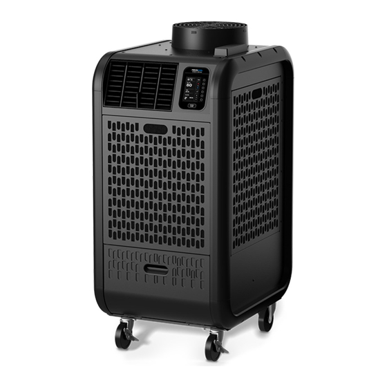
Names of Parts Condenser Air Outlet Flange Antenna Cold Air Control Panel Outlet Grill Condenser Air Inlet Panel Evaporator Air Inlet Panel Drain Tank Cover Top Panel Logo Side Panel Upper Rear Panel Service Panel Lower Rear Panel Power Cord Holder Caster Power Cord... -
Page 9: Internal Structure
Internal Structure Communication Module Condenser Fan Drain Tank Compressor Drain Switch Control Box Evaporator Condenser Evaporator Fan Capillary Tube Fan Motor Drain Pan... -
Page 10: Specifications
SPECIFICATIONS Technical Specifications ITEM SPECIFICATIONS Electronic Features Control Programmable Cooling Capacity * Total Capacity 16,800 Btu/h Power Requirement 115V, 1Phase, 60Hz Total Power Consumption * 1.7 kW Current Consumption * 14.5 amps Electrical Characteristics Starting Current 65 amps Recommended Fuse Size 20 amps Min. - Page 11 Technical Specifications ITEM SPECIFICATIONS Internal Overload Relay for 320°F ± 9°F (160°C ± 5°C) Compressor 39.5 amps Safety Device Anti-Freezing Thermostat for On: 60°F ± 1.8°F (16°C ± 1°C) Evaporator Off: 27°F ± 1.8°F (-3°C ± 1°C) No voltage contact input Fire Alarm lnput Contact resistance: less than 100 ohm...
-
Page 12: Characteristics
Characteristics <Cooling Capacity Curve> <Cool Air Temperature Difference Curve> 25.2(14) 23.4(13) 21.6(12) 19.8(11) 18.0(10) 16.2(9) 14.4(8) 12.6(7) 95(35) 10.8(6) 86(30) 9.0(5) 77(25) 68(20) Relative Humidity (%) (10) (15) (20) (25) Wet Bulb Temp. °F (°C) <Power Consumption Curve> <Current Consumption Curve> 95(35) 95(35) 86(30) -
Page 13: Service Information
SERVICE INFORMATION Machine Status The status of functional parts can be displayed while the unit is running. HOME > MENU > SERVICES > MACHINE INFORMATION > MACHINE STATUS CLIMATE PRO MON 12:00 PM MACHINE BACK STATUS 75 F Multi-function buttons CTS1 54 F CTS2... -
Page 14: Machine Records
Machine Records The history of connection time, compressor operating time, defrosting time, fan operating time, and self-diagnostic codes are displayed while the unit is running. HOME > MENU > SERVICES > MACHINE INFORMATION > MACHINE RECORDS CLIMATE PRO MON 12:00 PM MACHINE BACK RECORDS... -
Page 15: Troubleshooting
TROUBLESHOOTING Initial Inspection Before troubleshooting, the following inspection should be performed. 1. Check the voltage of the power source. 115 V, 1 Phase, 60 Hz 2. Check the operation and condition of the fuse or circuit breaker in the power source. 3. -
Page 16: Self-Diagnostic Codes
Self-Diagnostic Codes When a self-diagnostic code is displayed on the LCD, the unit stops operation, relay contact RL07 for terminal OS-1 and OS2 is closed. CODE CONDITION POSSIBLE CAUSE SOLUTION Alarm device connected to 1. Check FA-1, FA-2 connection Alarm device 1 is FA-1 and FA-2 of terminal 2. -
Page 17: Troubleshooting Chart
Troubleshooting Chart PROBLEM POSSIBLE CAUSE SOLUTION Check and fix power Power failure supply and connection Ground fault protective breaker is tripped Reset breaker No display on LCD screen Defective ground fault protective breaker Repair or replace breaker Unit does not operate LCDI Power cord is tripped Reset power cord... - Page 18 Troubleshooting Chart PROBLEM POSSIBLE CAUSE SOLUTION Operating near minimum or maximum of Review room environment operating temperature range Dirt in indoor or outdoor heat exchanger Clean heat exchanger Poor cooling Air volume Compressor Frosting on the refrigerant line caused due Service refrigeration performance normal...
- Page 19 Troubleshooting Chart PROBLEM POSSIBLE CAUSE SOLUTION Cracks in drain pan Replace drain pan Drain hose is blocked or damaged Unblock or repair drain Water leaking from unit (Optional drain pump) hose Reversed air flow from drain hole due to Clean air filters excessive negative pressure inside of unit Fan interference Adjust interfering section...
-
Page 20: Inspection Before Disassembly
Inspection Before Disassembly 1. Inspection of plate fins on heat exchangers Remove air filters and check plate fins for any dirt, dust, lint, or debris that may cause insufficient cooling performance. If necessary, clean the plate fins. Plate Fins 2. Inspection of cooling capacity performance Measure the difference in air temperature between the inlet of the evaporator and the cool air vent. -
Page 21: Disassembly
DISASSEMBLY WARNING • Electrical work must be performed by qualified electrical personnel. Failure to use qualified electrical personnel for electrical work may cause fire, electric shock, injury, malfunction or water leaks. • Use genuine MovinCool parts for servicing. Non-genuine parts may cause fire, electric shock or water leaks. -
Page 22: Removal Of Panels
Removal of Panels 1. Open the drain tank cover and remove the tank. 2. Remove the evaporator and condenser filter panels. 3. Loosen the bottom two (2) screws and remove the other seven (7) M4 x L10 screws. Move the service panel upward and remove it from the logo side panel. - Page 23 Removal of Panels 5. Power cord holder can be removed from the lower rear panel. Remove the four (4) M4 x L10 screws and remove the power cord holder. Screw (4) M4 x L10 6. Remove the ten (10) M4 x L10 screws and one (1) M4 x L12 screw.
- Page 24 Removal of Panels 9. Remove the five (5) M4 x L10 screws and remove the upper front panel. Screw (5) M4 x L10 10. Remove the four (4) wires of the antenna from Wire of Antenna (4) the communication module in the control box. Communication Module 11.
-
Page 25: Removal Of Louver
Removal of Louver Louver can be removed from the upper front panel by releasing either of the lock tabs from notches. Notch Lock Tab Louver Upper Front Panel 1. Lift the bottom of the louver upward. 2. Slide the louver a little to the right or left so as to release the lock tab from the notch and pull out the louver. -
Page 26: Removal Of Bumpers
Removal of Bumpers Logo side panel 1. Remove the five (5) M4 x L12 screws and remove the bumper 2. Remove the five (5) M4 x L12 screws and remove the bumper 3. Remove the five (5) M4 x L12 screws and remove the bumper 4. - Page 27 Removal of Bumpers Condenser side panel 1. Remove the five (5) M4 x L12 screws and remove the bumper 2. Remove the five (5) M4 x L12 screws and remove the bumper 3. Remove the five (5) M4 x L12 screws and remove the bumper 4.
-
Page 28: Removal Of Electrical Parts
Removal of Electrical Parts 1. Control box a) Remove the service panel from the logo side panel. (See step 3 on page 22) b) Remove the following number of screws and remove each electrical part from the control box. - Communication module: two (2) screws - Terminal block 1: two (2) screws - Terminal block 2: two (2) screws - Compressor motor capacitor: one (1) screw... - Page 29 Removal of Electrical Parts 2. Relay Board a) Remove the six (6) supports with needle-nose pliers and remove relay board from the control box. Note: Be careful not to damage the relay board. b) Disconnect the ten (10) connectors from the relay board. CN21 (Red, Blue, Brown, Orange, White) To Fan Motor Supports (6)
- Page 30 Removal of Electrical Parts 3. Control Panel (see "Removal of Panels") a) Follow step 2, 3, 4, 6, and 7 in “Removal of Panels” section. b) Disconnect the CN1 and CN2 connectors from the control board. c) Remove the five (5) M4 x L10 screws and remove the upper front panel. Screw (5) M4 x L10 Control board...
-
Page 31: Removal Of Antenna
Removal of Antenna 1. Follow step 2, 3, 4, and 7 in “Removal of Panels” section. 2. Remove the four (4) wires of the antenna from Wire of Antenna (4) the communication module in the control box. Communication Module 3. Remove the two (2) M4 x L10 screws from underneath the top panel to detach antenna from the top panel. -
Page 32: Removal Of Communication Module
Removal of Communication Module Communication Module Hardware Description Battery Cover Reset button Mode Button Battery Cover Screws Battery ON/OFF Switch Service Cover LED Indicators... - Page 33 Removal of Communication Module Table of LED Indication LABEL NAME COLOR LED “ON” LED “OFF” LED BLINKING Power LED Working Sleeping Error NOT in Receiving data via Device LED Orange In Inspection Mode* Inspection Mode DEVICE I/F Port GNSS Fixed GNSS Not Fixed GNSS LED Blue...
- Page 34 Removal of Communication Module 2. Battery Removal and Installation Model SC-04002-02 Battery Specification Nominal Voltage 3.7V Nominal Capacity 2500 mAh Note: Before disconnecting the battery, place the battery switch to “OFF” position. (See section 4, Set Communication Module to Operate by Internal Battery) a) Remove two screws from battery cover.
- Page 35 Removal of Communication Module 3. I/F Cable (see “Removal of Electrical Parts”) a) Follow step in control panel removal then disconnect CN2 from the control board. b) Disconnect I/F connector from communication module. 4. Set Communication Module to Operate by Internal Battery Service Cover a) Remove service cover...
- Page 36 Removal of Communication Module 5. Reset Communication Module a) Remove service panel b) Use a nylon or wooden tool to press RESET button of the communication module CAUTION • Do not use sharp objects to press the reset button as it may damage the control panel. c) “P”...
-
Page 37: Removal Of Blower Assembly
Removal of Blower Assembly Condenser Fan Casing Condenser Fan Condenser Fan Casing Evaporator Fan Casing Evaporator Fan Motor Stay Fan Motor Frame-Sub Assy... - Page 38 Removal of Blower Assembly 1. Remove the five (5) M4 x L12 screws and remove the half condenser fan casing. Screw (5) M4 x L12 2. Loosen the set screw and remove the Set Screw condenser fan. Note: When reinstalling the condenser fan, fasten the set screw at the torque of 12.6 ±...
- Page 39 Removal of Blower Assembly 5. Remove the four (4) nuts and remove the fan motor assembly. Nuts (4) 6. Loosen the set screw and remove the evaporator fan. Note: When reinstalling the evaporator fan, fasten the set screw at the torque of 5.5 ± 0.5 ft·lbf Set Screw (7.4 ±...
-
Page 40: Inspection Of Parts
INSPECTION OF PARTS Capacitor 1. Ohmmeter method Set the ohmmeter to the 10M range. Place the two probes against the two terminals of the capacitor. At first, the ohmmeter should indicate a small value, and then the reading should gradually increase towards infinity. This indicates that the capacitor is charging. If the reading indicates infinity immediately (open) or the ohmmeter fails to move from 0 (short), replace the capacitor. -
Page 41: Fan Motor
Fan Motor Check the resistance values across the two pins listed in the table below on the 8-pin fan motor connector with an ohm-meter. If the measured values are outside of the acceptable values, then replace the fan motor. 8-pin connector 8 7 6 5 Connector Pin No. -
Page 42: Compressor
Compressor 1. Remove the nut and remove the cover from the compressor. Cover 2. Compressor Motor Disconnect the terminals: C, R and S from the compressor motor and check resistance across the terminals: Between terminals at 68 °F (20 °C) - R-C Approx. -
Page 43: Thermistor
Thermistor Check the resistance value across the 2 pins of 7- pin thermistor connector with an ohm-meter. - RTS (Evaporator air inlet thermistor): Pin-2 and pin-7 - CTS1 (Evaporator pipe thermistor): Pin-1 and pin-4 If the measured value is outside of the thermistor specification, replace the thermistor. 7-pin connector CTS1 CTS1... -
Page 44: Refrigeration System Repair
REFRIGERATION SYSTEM REPAIR Brazing If a problem with refrigerant system is found, replace or repair the relevant part. After replacing any part, all connections must be brazed. WARNING To avoid burns, lack of oxygen or unit malfunction: • Brazing must be performed by a qualified technician only. •... - Page 45 Brazing 4. Use of dry nitrogen gas The brazing flame oxidizes the inner surface of the pipe. To prevent this, introduce dry nitrogen gas from the pinch-off tube of the refrigeration cycle at a rate of 0.27 gal/min (1 L/min); adjust with the flow regulator.
-
Page 46: Replacement Of Refrigeration Cycle Parts
Replacement of Refrigeration Cycle Parts The parts of refrigeration system are connected with copper tubes by brazing each connection. Condenser Evaporator Evaporator Outlet Pipe Condenser Inlet Pipe Capillary Tube Evaporator Pipe Condenser Outlet Pipe Compressor Discharge Pipe Compressor Suction Pipe Accumulator Compressor... - Page 47 Replacement of Refrigeration Cycle Parts Before replacing the parts, recover the refrigerant using standard recovery procedures and equipment. When recovering the refrigerant, use the pinch-off tubes on the low pressure side (tube 1) and high pressure side (tube 2) as shown. To prevent oxidation, introduce dry nitrogen gas from the pinch-off tube at a rate of 0.27 gal/min (1 L/min);...
-
Page 48: Charging The System With R-410A Refrigerant
Charging the System with R-410A Refrigerant Prepare the following items: - Gauge manifold - Vacuum pump - R-410A refrigerant cylinder (Use a max of 90% of the initial weight) - Scale - Safety goggles - Heavy-duty work gloves WARNING When handling refrigerant, the following precautions should always be observed. Failure to do so may cause explosion, fire, loss of vision, lack of oxygen, burns, injury or unit malfunction. - Page 49 Charging the System with R-410A Refrigerant 1. Connection of gauge manifold Process Tube Fitting a) Remove the crushed end of the pinch- Charging Hose off tube on the high pressure side of the Side refrigerant cycle with a pipe cutter. Refrigerant b) Connect the process tube fitting to the Cycle Side...
- Page 50 Charging the System with R-410A Refrigerant WARNING Avoid working near flammable materials. Working near flammable materials may cause explosion or fire. Refrigerant may generate toxic gas if it comes into contact with an open flame or heated metal. 4. Checking gas leak Valve Setting a) Remove the charging hose from the Closed...
- Page 51 Charging the System with R-410A Refrigerant 6. Checking gas leak Valve Setting a) Remove the charging hose from the vacuum Closed Closed pump and connect it to the refrigerant Air Purging cylinder. Open Valve b) Loosen the nut on the gauge manifold side of the charging hose and open the valve of the refrigerant cylinder.
-
Page 52: Reassembly
REASSEMBLY Reassemble the unit in the reverse order of removal. The following parts require special care in reassembling the unit. Wiring Diagram Perform all wiring or rewiring as referenced in the wiring diagram. AC115V 60Hz OL C CN21 CN01 CN02 CN22 CN23 RL01... -
Page 53: Compressor Mounting
Compressor Mounting 1. Install the three (3) cushions on the bolts . 2. Mount the compressor in the unit. 3. Insert the three (3) nuts and fasten at the torque of 8.3 ± 2.1 ft·lbf (11.3 ± 2.9 N·m) Nut (3) Cushion (3) Caster Maintenance Lubricate bearings in caster as needed with standard bearing grease using the zerk fitting. -
Page 54: Data Privacy Disclosure
DATA PRIVACY DISCLOSURE Tracking of Machine Operation Data This Unit is equipped with an embedded module that collects and transmits to us data on the Unit’s operational performance (“Machine Operation Data”), including 1. Hours of operation 2. Control Panel settings 3. - Page 55 Sharing of Data We shall use Machine Operation Data primarily for our own business purposes. We may also share your Unit’s Machine Operation Data with the distributor, reseller or owner that sells or leases the Unit to you. This means that they will be able to determine the geolocation of the Unit.
- Page 56 DENSO PRODUCTS AND SERVICES AMERICAS, INC. Long Beach, CA 90810 www.movincool.com First Edition: May 2020 P/N: SVM02-00...