Table of Contents
Advertisement
Quick Links
Advertisement
Table of Contents

Related Manuals for Gigabyte R161-R12


Summary of Contents for Gigabyte R161-R12
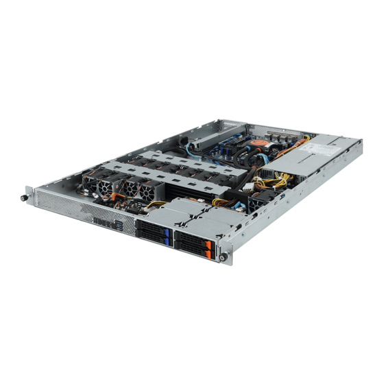
- Page 1 R161-R12 High Efficiency Liquid Cooling System User Manual Rev. 1.1...
- Page 2 GIGABYTE's prior written permission. Documentation Classifications In order to assist in the use of this product, GIGABYTE provides the following types of documentation: User Manual: detailed information & steps about the installation, configuration and use this product (e.g. motherboard, server barebones), covering hardware and BIOS.
- Page 3 Conventions The following conventions are used in this user's guide: NOTE! Gives bits and pieces of additional information related to the current topic. CAUTION! Gives precautionary measures to avoid possible hardware or software problems. WARNING! Alerts you to any damage that might result from doing or not doing specific actions.
- Page 4 Server Warnings and Cautions Before installing a server, be sure that you understand the following warnings and cautions. WARNING! To reduce the risk of electric shock or damage to the equipment: • Do not disable the power cord grounding plug. The grounding plug is an important safety feature.
- Page 5 Electrostatic Discharge (ESD) CAUTION! ESD CAN DAMAGE DRIVES, BOARDS, AND OTHER PARTS. WE RECOMMEND THAT YOU PERFORM ALL PROCEDURES AT AN ESD WORKSTATION. IF ONE IS NOT AVAILABLE, PROVIDE SOME ESD PROTECTION BY WEARING AN ANTI-STATIC WRIST STRAP AT- TACHED TO CHASSIS GROUND -- ANY UNPAINTED METAL SURFACE -- ON YOUR SERVER WHEN HANDLING PARTS.
- Page 6 CAUTION! Risk of explosion if battery is replaced incorrectly or with an incorrect type. Replace the battery only with the same or equivalent type recommended by the manufacturer. Dispose of used bat- teries according to the manufacturer’s instructions.
-
Page 7: Table Of Contents
Table of Contents Chapter 1 Hardware Installation ...................10 Installation Precautions .................. 10 Product Specifications ..................11 System Block Diagram ................... 14 Chapter 2 System Appearance ..................15 Front View ...................... 15 Rear View ....................... 15 Front Panel LED and Buttons ................ 16 Rear System LAN LEDs ................. - Page 8 5-2-6 Acoustic Management Configuration ..............49 5-2-7 SIO Configuration ....................50 5-2-8 PCI Subsystem Settings ..................51 5-2-9 Network Stack Configuration ..................52 5-2-10 Post Report Configuration ..................53 5-2-11 NVMe Configuration ....................54 5-2-12 USB Configuration ....................55 5-2-13 Chipset Configuration .....................56 5-2-14 Tls Auth Configuration ....................57 5-2-15 Intel(R) I350 Gigabit Network Connection ..............58 5-2-16 VLAN Configuration ....................60 5-2-17 Driver Health ......................62...
- Page 9 5-9-4 Intel UPI POST Codes ..................120 5-9-5 Intel UPI Error Codes ...................120 5-9-6 Intel MRC POST Codes ..................121 5-9-7 Intel MRC Error Codes ..................121 5-9-8 Intel PM POST Codes ..................122 5-9-9 Intel PM POST Codes ..................122 5-10 BIOS POST Beep code (AMI standard) ............123 5-10-1 PEI Beep Codes ....................123 5-10-2 DXE Beep Codes ....................123...
-
Page 10: Chapter 1 Hardware Installation
Chapter 1 Hardware Installation Installation Precautions The motherboard/system contain numerous delicate electronic circuits and components which can become damaged as a result of electrostatic discharge (ESD). Prior to installation, carefully read the service guide and follow these procedures: • Prior to installation, do not remove or break motherboard S/N (Serial Number) sticker or warranty sticker provided by your dealer. -
Page 11: Product Specifications
Product Specifications Intel® Core™ X series 44-lane/28-lane processors Š Socket Intel® Core™ X series 44-lane/28-lane processors Š Chipset System on Chip Š Memory 8 x DIMM slots Š DDR4 memory modules supported only Š Quad channel memory architecture Š Support for non-ECC Un-buffered DIMM Š... - Page 12 Internal 3 x Power supply connectors Š Connectors 5 x SlimSAS connectors Š 2 x fan headers Š 1 x USB 3.0 header Š 1 x TPM header Š 1 x VROC connector Š 1 x Front panel header Š 1 x HDD back plane board header Š...
- Page 13 System Aspeed® AST2500 management controller Š Management Avocent® MergePoint IPMI 2.0 web interface: Š Network settings Š Network security settings Š Hardware information Š Users control Š Services settings Š IPMI settings Š Sessions control Š LDAP settings Š Power control Š...
-
Page 14: System Block Diagram
System Block Diagram PCIe x16 PCIe3.0 x16 Switch Slot4 PCIe x16 + x16 PCIe3.0 x16 Slot6 PCIe3.0 x8 2-bay 2.5” NVMe Skylake-X PCIe3.0 x4 Cascade Lake-X 4-Channel Non-ECC UDIMM DDR4, 8 x DIMM slots LGA2066 (Socket R4) 5 x SlimLine 2 x USB3.0 2 x USB3.0 (Rear Side) -
Page 15: Chapter 2 System Appearance
Chapter 2 System Appearance Front View HDD #2 HDD #0 NVMe Compa bile HDD #3 HDD #1 NVMe Compa bile Description Front Panel LEDs and buttons Front USB 3.0 ports Orange HDD Latches Support NVMe • Please Go to Chapter 2-3 Front Panel LED and Buttons for detail description of function LEDs. -
Page 16: Front Panel Led And Buttons
Front Panel LED and Buttons Name Color Status Description ID Button Press the button to activate system identification Green System is powered on Green Blink System is in ACPI S1 state (sleep mode) Power button • System is not powered on or in ACPI S5 state with LED (power off) •... -
Page 17: Rear System Lan Leds
Rear System LAN LEDs Name Color Status Description Yellow 1 Gbps data rate 1GbE Green 100 Mbps data rate Speed LED 10 Mbps data rate Link between system and 1GbE Green network or no access Link/ Blink Data transmission or receiving is occurring Activity No data transmission or receiving is occurring... -
Page 18: Hard Disk Drive Leds
Hard Disk Drive LEDs HDD Present RAID SKU LED1 Locate Rebuilding Fault Access (No Access) Disk LED Green Green ON(*1) (LED on Back Panel) Amber Amber No RAID configuration Green ON(*1) Green (via HBA, ICH) Removed HDD Slot (LED on Back Panel) Amber Amber Green... -
Page 19: Chapter 3 System Hardware Installation
Chapter 3 System Hardware Installation Pre-installation Instructions Computer components and electronic circuit boards can be damaged by discharges of static electricity. Working on computers that are still connected to a power supply can be extremely dangerous. Follow the simple guidelines below to avoid damage to your computer or injury to yourself. -
Page 20: Removing Chassis Cover
Removing Chassis Cover Before you remove or install the system cover • Make sure the system is not turned on or connected to AC power. Follow these instructions to remove the system cover: Loosen and the two thumbscrew at the rear of the system. Remove the single secrew at the front of the system. -
Page 21: Installing The Liquid Cooling Module
Installing the Liquid Cooling Module Before you remove or install the liquid cooling module: • Make sure the system is not turned on or connected to AC power. Follow these instructions to install the liquid cooling module: Remove the screws securing brackets . Remove the brackets from the system. - Page 22 Blue Orange Orange Pump Cable Connector Blue (CPU_FAN) System Hardware Installation - 22 -...
-
Page 23: Installing The Memory
Installing the Memory Read the following guidelines before you begin to install the memory: • Make sure that the motherboard supports the memory. It is recommended that memory of the same capacity, brand, speed, and chips be used. • Always turn off the computer and unplug the power cord from the power outlet before installing the memory to prevent hardware damage. -
Page 24: Installing A Memory
3-3-2 Installing a Memory Before installing a memory module, make sure to turn off the computer and unplug the power cord from the power outlet to prevent damage to the memory module. Be sure to install DDR4 DIMMs on this motherboard. Follow these instructions to install the Memory: Insert the DIMM memory module vertically into the DIMM slot, and push it down. -
Page 25: Installing The Pci Expansion Card
Installing the PCI Expansion Card • Voltages can be present within the server whenever an AC power source is connected. This voltage is present even when the main power switch is in the off position. Ensure that the system is powered-down and all power sources have been disconnected from the server prior to installing a PCI card. -
Page 26: Installing The Hard Disk Drive
Installing the Hard Disk Drive Read the following guidelines before you begin to install the Hard disk drive: • Take note of the drive tray orientation before sliding it out. • The tray will not fit back into the bay if inserted incorrectly. •... -
Page 27: Replacing The Fan Assemblly
Replacing the FAN Assemblly Follow these instructions to replace the fan assembly: Lift up the fan assembly from the chassis. Reverse the previous steps to install the replacement fan assembly. - 27 - System Hardware Installation... -
Page 28: Replacing The Power Supply
Replacing the Power Supply Follow these instructions to replace the power supply: Press the retaining clip on the right side of the power supply along the direction of the arrow. Pull up the power supply handle at the same time and pull out the power supply. Insert the replacement power supply firmly into the chassis. -
Page 29: Cable Routing
Cable Routing System Power Cable Front IO Board Power Cable OLD_REV OLD_REV OLD_REV OLD_REV OLD_REV OLD_REV OLD_REV OLD_REV OLD_REV OLD_REV OLD_REV OLD_REV OLD_REV OLD_REV OLD_REV OLD_REV Front Panel USB 3.0 Cable Front IO Board Power Cable OLD_REV OLD_REV OLD_REV OLD_REV OLD_REV OLD_REV OLD_REV... - Page 30 HDD Back Plane Board Power Cable HDD Back Plane Board Signal Cable OLD_REV OLD_REV OLD_REV OLD_REV OLD_REV OLD_REV OLD_REV OLD_REV OLD_REV OLD_REV OLD_REV OLD_REV OLD_REV OLD_REV OLD_REV OLD_REV On-Board SATA to HDD Back Plane Board NVMe Cable Cable OLD_REV OLD_REV OLD_REV OLD_REV OLD_REV...
- Page 31 System Fan Cable OLD_REV OLD_REV OLD_REV OLD_REV OLD_REV OLD_REV OLD_REV OLD_REV OLD_REV OLD_REV OLD_REV OLD_REV OLD_REV OLD_REV OLD_REV OLD_REV OLD_REV OLD_REV OLD_REV OLD_REV OLD_REV OLD_REV OLD_REV OLD_REV OLD_REV OLD_REV OLD_REV OLD_REV OLD_REV OLD_REV OLD_REV OLD_REV CAUTION! To connect system fan connector, follow the instruction: •...
- Page 32 SMBus Cable PMBus Cable OLD_REV OLD_REV OLD_REV OLD_REV OLD_REV OLD_REV OLD_REV OLD_REV OLD_REV OLD_REV OLD_REV OLD_REV OLD_REV OLD_REV OLD_REV OLD_REV System Hardware Installation - 32 -...
-
Page 33: Chapter 4 Motherboard Components
Chapter 4 Motherboard Components Motherboard Components 14 15 16 17 Item Description 2 x 4 Pin CPU Power Connector Auxiliary Power Connector for Overclocking 2 x 12 Pin System Power Connector Front Panel Header VROC Upgrade Module CPU Fan Connector (for Liquid Cooling Pump) SlimLine 4i Connector (PCIe Signal) SlimLine 4i Connector (PCIe Signal) SlimLine 4i Connector (PCIe Signal) - Page 34 USB 3.0 Connector TPM Connector System Battery Cable Connector PMBus Connector M.2 slot (PCIe Gen3 x4, Support NGFF-2280, M-Key) IPMB Connector Proprietary Riser Slot 2 x 15 Pin HDD Back Plane Board Connector PCIe x16 Slot Motherboard Components - 34 -...
-
Page 35: Jumper Setting
Jumper Setting Default Recovery Enable ME_RCVR ME Force Enable Update Default ME_UPDATE BIOS Default Recovery Password Enable Enable BIOS_RCVR Clear Default BIOS_PWD Enable Clear CMOS CLR_CMOS Default - 35 - Motherboard Components... -
Page 36: Chapter 5 Bios Setup
Chapter 5 BIOS Setup BIOS (Basic Input and Output System) records hardware parameters of the system in the EFI on the motherboard. Its major functions include conducting the Power-On Self-Test (POST) during system startup, saving system parameters and loading operating system, etc. BIOS includes a BIOS Setup program that allows the user to modify basic system configuration settings or to activate certain system features. - Page 37 Main This setup page includes all the items in standard compatible BIOS. Advanced This setup page includes all the items of AMI BIOS special enhanced features. (ex: Auto detect fan and temperature status, automatically configure hard disk parameters.) ...
-
Page 38: The Main Menu
The Main Menu Once you enter the BIOS Setup program, the Main Menu (as shown below) appears on the screen. Use arrow keys to move among the items and press <Enter> to accept or enter other sub-menu. Main Menu Help The on-screen description of a highlighted setup option is displayed on the bottom line of the Main Menu. - Page 39 Parameter Description BIOS Information Access Level Display the privileges level information. Project Name Displays the project name information. Project Version Displays version number of the BIOS setup utility. Build Date and Time Displays the date and time when the BIOS setup utility was created. BMC Information (Note) BMC Firmware Version...
-
Page 40: Advanced Menu
Advanced Menu The Advanced menu display submenu options for configuring the function of various hardware components. Select a submenu item, then press <Enter> to access the related submenu screen. BIOS Setup - 40 -... -
Page 41: Pch-Fw Configuration
5-2-1 PCH-FW Configuration Parameter Description ME Firmware Version Displays the ME firmware version information. ME Firmware Mode Displays the ME firmware mode. ME Firmware SKU Displays the ME firmware SKU information. ME File System Integrity Value Displays the ME file system integrity value information. ME Firmware Status 1/2 Displays the ME firmware status 1/2 information. -
Page 42: Trusted Computing
5-2-2 Trusted Computing Parameter Description Configuration Enable/Disable the TPM support feature. Security Device Support Options available: Enable/Disable. Default setting is Enable. BIOS Setup - 42 -... -
Page 43: Smart Settings
5-2-3 SMART Settings Parameter Description SMART Settings Enable/Disable SMART Self Test on all HDDs during POST. SMART Self Test Options available: Enabled/Disabled. Default setting is Enabled. - 43 - BIOS Setup... -
Page 44: Serial Port Console Redirection
5-2-4 Serial Port Console Redirection Parameter Description Console redirection enables the users to manage the system from a COM1 Console remote location. Redirection (Note)) Options available: Enabled/Disabled. Default setting is Disabled. Press [Enter] to configure advanced items. Please note that this item is configurable when COM1 Console Redirection is set to Enabled. - Page 45 Parameter Description Parity Š – A parity bit can be sent with the data bits to detect some transmission errors. – Even: parity bit is 0 if the num of 1's in the data bits is even. – Odd: parity bit is 0 if num of 1's in the data bits is odd. –...
- Page 46 Parameter Description Legacy Console Redirection Press [Enter] to configure advanced items. Redirection COM Port Š – Selects a COM port for Legacy serial redirection. – Default setting is COM1. Resolution Š – Selects the number of rows and columns used in Console Redirection for legacy OS support.
- Page 47 Parameter Description Flow Control Š – Flow control can prevent data loss from buffer overflow. When sending data, if the receiving buffers are full, a 'stop' signal can Serial Port for Out-of-Band be sent to stop the data flow. Once the buffers are empty, a 'start' EMS Console Redirection signal can be sent to re-start the flow.
-
Page 48: Intel Txt Information
5-2-5 Intel TXT Information Parameter Description Intel TXT Information Chipset Displays the chipset is production or debug fused. BiosAcm Displays the Bios Acm is production or debug fused. Chipset Txt Displays the chipset status of TXT support. Cpu Txt Displays the CPU status of TXT support. Error Code Displays the Intel TXT shut down error code. -
Page 49: Acoustic Management Configuration
5-2-6 Acoustic Management Configuration Parameter Description Enable/Disable the automatic acoustic management function. Acoustic Management Configuration Options available: Enabled/Disabled. Default setting is Disabled. - 49 - BIOS Setup... -
Page 50: Sio Configuration
5-2-7 SIO Configuration Parameter Description AMI SIO Driver Version Displays the AMI SIO driver version information. Super IO Chip Logical Device(s) Configuration Press [Enter] to configure advanced items. Use This Device Š – When set to Enabled allows you to configure the serial port settings. When set to Disabled, displays no configuration for the serial port. -
Page 51: Pci Subsystem Settings
5-2-8 PCI Subsystem Settings Parameter Description PCI Bus Driver Version Displays the PCI Bus Driver version information. PCI Devices Common Settings Enable/Disable PCI device to generate PERR#. PERR# Generation Options available: Enabled/Disabled. Default setting is Disabled. Enable/Disable PCI device to generate SERR#. SERR# Generation Options available: Enabled/Disabled. -
Page 52: Network Stack Configuration
5-2-9 Network Stack Configuration Parameter Description Enable/Disable the UEFI network stack. Network Stack Options available: Enabled/Disabled. Default setting is Enabled. Enable/Disable the Ipv4 PXE feature. Ipv4 PXE Support (Note) Options available: Enabled/Disabled. Default setting is Enabled. Enable/Disable the Ipv4 HTTP feature. Ipv4 HTTP Support (Note) Options available: Enabled/Disabled. -
Page 53: Post Report Configuration
5-2-10 Post Report Configuration Parameter Description Post Report Configuration Error Message Report Enable/Disable the POST Error Message support. Post Error Message Options available: Enabled/Disabled. Default setting is Enabled. - 53 - BIOS Setup... -
Page 54: Nvme Configuration
5-2-11 NVMe Configuration Parameter Description NVMe Configuration Displays the NVMe devices connected to the system BIOS Setup - 54 -... -
Page 55: Usb Configuration
5-2-12 USB Configuration Parameter Description USB Configuration USB Devices: Displays the USB devices connected to the system. Enable/Disable the XHCI (USB 3.0) Hand-off support. XHCI Hand-off Options available: Enabled/Disabled. Default setting is Enabled. USB Mass Storage Driver Enable/Disable the USB Mass Storage Driver Support. Support Options available: Enabled/Disabled. -
Page 56: Chipset Configuration
5-2-13 Chipset Configuration Parameter Description Defines the power state to resume to after a system shutdown that is due to an interruption in AC power. When set to Last State, the system will return to the active power state prior to shutdown. When set to Restore on AC Power Loss (Note) Power Off, the system remains off after power shutdown. -
Page 57: Tls Auth Configuration
5-2-14 Tls Auth Configuration Parameter Description Press [Enter] for configuration of advanced items. Enroll Cert Š – Press [Enter] to enroll a certificate • Enroll Cert Using File • Cert GUID Server CA Configuration Input digit character in 1111111-2222-3333-4444-1234567890ab format. –... -
Page 58: Intel(R) I350 Gigabit Network Connection
5-2-15 Intel(R) I350 Gigabit Network Connection Parameter Description Press [Enter] to configure advanced items. Link Speed Š – Allows for automatic link speed adjustment. – Options available: Auto Negotiated, 10 Mbps Half, 10 Mbps Full, 100 Mbps Half, 100 Mbps Full. Default setting is Auto Negotiated. NIC Configuration Wake On LAN Š... - Page 59 Parameter Description Chip Type Displays the technical specifications for the Network Interface Controller. PCI Device ID Displays the technical specifications for the Network Interface Controller. PCI Address Displays the technical specifications for the Network Interface Controller. Link Status Displays the technical specifications for the Network Interface Controller. MAC Address Displays the technical specifications for the Network Interface Controller.
-
Page 60: Vlan Configuration
5-2-16 VLAN Configuration BIOS Setup - 60 -... - Page 61 Parameter Description Press [Enter] to configure advanced items. Create new VLAN Š VLAN ID Š – Sets VLAN ID for a new VLAN or an existing VLAN. – Press the <+> / <-> keys to increase or decrease the desired values. –...
-
Page 62: Driver Health
5-2-17 Driver Health Parameter Description Driver Health Displays driver health status of the devices/controllers if installed BIOS Setup - 62 -... -
Page 63: Chipset Setup Menu
Chipset Setup Menu Chipset Setup menu displays submenu options for configuring the function of Platform Controller Hub(PCH). Select a submenu item, then press <Enter> to access the related submenu screen. - 63 - BIOS Setup... -
Page 64: Pch-Io Configuration
5-3-1 PCH-IO Configuration Parameter Description PCH-IO Configuration Press [Enter] to configure advanced items. SATA Controller Š – Enable/Disable SATA device. – Options available: Enabled/Disabled. Default setting is Enabled. SATA Mode Selection Š – Configures on chip SATA type. – AHCI Mode: the SATA controller enables its AHCI functionality. Then the RAID function is disabled and cannot be access the RAID setup utility at boot time. - Page 65 Parameter Description Spin Up Device Š SATA And RST – Enable/Disable the SATA ports straggerred spin up function. Configuration (continued) – Options available: Enabled/Disabled. Default setting is Disabled - 65 - BIOS Setup...
- Page 66 5-3-2 Processor Configuration BIOS Setup - 66 -...
-
Page 67: Processor Configuration
Parameter Description Processor Configuration Press [Enter] to configure advanced items. CPU Socket 0 Configuration Š – Press [Enter] to configure advanced items. Core Disable Bitmap(Hex) (for CPU socket 0/1) Š Per-Socket Configuration – Number of Cores to enable. 0 means all cores. FFFFFFF means to disable all cores. -
Page 68: Common Refcode Configuration
5-3-3 Common RefCode Configuration Parameter Description Common RefCode Configuration Selects MMCFG size. MMCFG Size Options available: 64M, 128M, 256M, 512M, 1G, 2G. Default setting is 256M. Selects the MMIO High Base setting. MMIO High Base Options available: 56T, 40T, 24T, 16T, 4T, 1T. Default setting is 56T. Selects the allocation size used to assign mmioh resources. -
Page 69: Memory Configuration
5-3-4 Memory Configuration Parameter Description Integrated Memory Controller (iMC) When set to Enable, the system enforces Plan Of Record restrictions for DDR4 frequency and voltage programming. When Enforce POR set to Auto, the system sets it to the MRC default settings. Options available: Auto, POR, Disable. - Page 70 Parameter Description Press [Enter] to configure advanced items. Static Virtual Lockstep Mode Š – Enable/Disable the Static Virtual Lockstep mode. – Options available: Disable/Enable. Default setting is Disable. Mirror Mode Š – Mirror Mode will set entire 1LM/2LM memory in system to be mirrored, consequently reducing the memory capacity Memory RAS Configuration by half.
-
Page 71: Iio Configuration
5-3-5 IIO Configuration Parameter Description IIO Configuration Press [Enter] to configure advanced items. ® Intel VT for Directed I/O (VT-d) Š – Enable/Disable the Intel VT for Directed I/O (VT-d) support function by reporting the I/O device assignment to VMM through DMAR ACPI Tables. - Page 72 Parameter Description Press [Enter] to configure advanced items. ® Intel VMD technology Š ® Intel VMD technology ® Intel VMD Configuration Š – Enable/Disable the Intel VMD support function. – Options available: Enable/Disable. Default setting is Disable. BIOS Setup - 72 -...
-
Page 73: Advanced Power Management Configuraiton
5-3-6 Advanced Power Management Configuraiton Parameter Description Advanced Power Management Configuration Press [Enter] to configure advanced items. SpeedStep (Pstates) Š – Conventional Intel SpeedStep Technology switches both voltage and frequency in tandem between high and low levels in response to processor load. –... - Page 74 Parameter Description Press [Enter] to configure advanced items. Autonomous Core C-State Š – Enable/Disable the Autonomous Core C-State Control. – Options available: Enable/Disable. Default setting is Disable. CPU C6 Report Š – Allows you to determine whether to let the CPU enter C6 mode in system halt state.
-
Page 75: Miscellaneous Configuration
5-3-7 Miscellaneous Configuration Parameter Description Miscellaneous Configuration Enable/Disable BIOS Guard Platform Protection Technology. BIOS Guard Options available: Enabled/Disabled. Default setting is Disabled. Enable/Disable the function to protect the flash part from malicious Flash Wear Out Protection writes intended to wear it out. Options available: Enabled/Disabled. -
Page 76: Runtime Error Logging
5-3-8 Runtime Error Logging BIOS Setup - 76 -... - Page 77 Parameter Description System Event Log Enable/Disable system error logging function. System Errors Options available: Enable/Disable. Default setting is Enable. When enabled, software error injection is supported by unlocking MSR S/W Error Injection Support 0x790. Options available: Enable/Disable. Default setting is Disable. Enable/Disable system memory poison function.
- Page 78 5-3-8-1 eMCA Settings Parameter Description eMCA Settings Enable/Disable EMCA logging function. EMCA Logging Support Options available: Enable/Disable. Default setting is Enable. Enable/Disable Local MCE firmware support. LMCE Support Options available: Enable/Disable. Default setting is Enable. Enable/Disable Ignore OS EMCA Opt-in and log feature. Ignore OS EMCA Opt-in Options available: Enable/Disable.
- Page 79 5-3-8-2 Error Injection Settings Parameter Description Error Injection Settings Mca Bank Error Injection Enable/Disable Mca Bank Error Injection Support. Support Options available: Enable/Disable. Default setting is Disable. Enable/Disable WHEA Error Injection support. Please disable DIRECTORY WHEA Error Injection MODE for memory error injection. Support Options available: Enable/Disable.
- Page 80 Parameter Description ME Seg Error Injection Enable/Disable ME Seg Error Injection Support. Support Options available: Enable/Disable. Default setting is Disable. Enable/Disable HA Parity Check feature. Enable HA Parity Check Options available: Enable/Disable. Default setting is Disable. Mca Bank Warm Boot Clear Enable/Disable Mca Bank Warm Boot Clear Errors feature.
- Page 81 5-3-8-3 Memory Error Enabling Parameter Description Memory Error Enabling Enable/Disable Memory Error. Memory Error Options available: Enable/Disable. Default setting is Enable. Enable/Disable Memory Corrected Error. Memory Corrected Error Options available: Enable/Disable. Default setting is Enable. Memory Leaky Bucket Value Sets Memory Leaky Bucket Value. (0x0000 - 0xffff) Selects Spare Interrupt type.
- Page 82 Parameter Description Press [Enter] to configure advanced items. CLR Max OC Ratio Š – Sets the maximum OC Ratio for the CLR Domain. CLR Min Ratio Š – Sets the minimum ratio for the CLR Domain. CLR Voltage Mode Š –...
- Page 83 5-3-8-4 IIO Error Enabling - 83 - BIOS Setup...
- Page 84 Parameter Description IIO Error Enabling IIO/PCH Global Error Enable/Disable IIO/PCH Error Support. Support Options available: Enable/Disable. Default setting is Enable. Enable/Disable IIO MCA Support. IIO MCA Support Options available: Enable/Disable. Default setting is Disable. Enable/Disable IIO Error Pin Programming. IIO Error Pin Programming Options available: Enable/Disable.
- Page 85 Parameter Description Enable/Disable IIO Coherent Interface Write Cache Un-correctable ECC IIO IRP0 wrcache uncecccs0 error reporting. error Options available: Enable/Disable. Default setting is Enable. Enable/Disable IIO Coherent Interface Write Cache Un-correctable ECC IIO IRP0 wrcache uncecccs1 error reporting. error Options available: Enable/Disable. Default setting is Enable. Enable/Disable IIO Coherent Interface protocol layer received poisoned IIO IRP0 protocol rcvd poison packet error reporting.
- Page 86 5-3-8-5 PCIe Error Enabling Parameter Description PCIe Error Enabling Enables and escalates Correctable Errors to error pins. Corrected Error Options available: Enable/Disable. Default setting is Enable. Enables and escalates Uncorrectable/Recoverable Errors to error pins. Uncorrected Error Options available: Enable/Disable. Default setting is Enable. Enables and escalates Fatal Errors to error pins.
- Page 87 Parameter Description PCIE Corrected Error Configures PCIe corrected error threshold. (0x001 - 0xfff) Threshold Enable/Disable PCIe AER corrected error. PCIE AER Corrected Errors Options available: Enable/Disable. Default setting is Enable. PCIE AER Advisory Nonfatal Enable/Disable PCIe AER nonfatal error. Error Options available: Enable/Disable.
-
Page 88: Oc Configuration Menu
OC Configuration Menu OC Configuration menu displays submenu options for configuring the function of Processor OverClocking, Memory OverClocking, Voltage Setting and Power & Performace. Select a submenu item, then press <Enter> to access the related submenu screen. BIOS Setup - 88 -... - Page 89 5-4-1 Processor OverClocking - 89 - BIOS Setup...
-
Page 90: Processor Overclocking
Parameter Description OverClocking Enable/Disable OverClocking feature. OverClocking Feature Options available: Enable/Disable. Default setting is Disable. Enable/Disable WatchDog Timer. Note: This option is ignored on debug WDT Enable BIOS. Options available: Enable/Disable. Default setting is Enable. Press [Enter] to configure advanced items. CPU Mode Š... - Page 91 Parameter Description Enable/Disable Adjust Pll Value - send the mailbox command to adjust Adjust Pll (Note) the Pll for Higher-BCLK Ratio combination. Options available: Enable/Disable. Default setting is Disable. Change PllTrim Value Changes Pll Value between +63 to -63. (Note) Change PLLTRIM Prefix Changes PLLTRIM Prefix to + or -.
-
Page 92: Memory Overclocking
5-4-2 Memory OverClocking Parameter Description Configures the maximum memory frequency. Memory Frequency Default setting is Auto. IMC BCLK Configures IMC BCLK. Default setting is Auto. Selects the XMP profile to use. XMP Profile Options available: Disable, Manual, Profile1. Default setting is Disable. BIOS Setup - 92 -... -
Page 93: Voltage Setting
5-4-3 Voltage Setting Parameter Description Configures CPU VR Loadline. CPU VR Loadline Options available: Auto, Level 1, Level 2, Level 3. Default setting is Auto. Enable/Disable SVID support to input voltage overrides. SVID Support Options available: Enabled/Disabled. Default setting is Enabled. Sets a value (0~2500 mV) for overriding the VccIN input voltage. - Page 94 Parameter Description VDDQ_CD Voltage Configures the settings of VDDQ_CD Voltage. Configures VR Power Limit. VR Power Limit Options available: Locked/Unclocked. Default setting is Locked. BIOS Setup - 94 -...
-
Page 95: Power & Performance
5-4-4 Power & Performance Parameter Description Power & Performance CPU-Power Management Control Press [Enter] to configure advanced items. Configures PL1 Power Limit in Watts. The value may vary from 0 to PL1 Power Limit fused value. If the value is 0, the fused value will be programmed. A value greater than fused TDP value will not be programmed. - Page 96 5-4-4-1 CPU-Power Management Control Parameter Description CPU-Power Management Control Selects the performance state that the BIOS will set starting from reset vector. Boot performance mode Options available: Max Battery, Max Non-Turbo Performance, Turbo Performance. Default setting is Max Non-Turbo Performance. Enable/Disable Race to Halt feature.
- Page 97 Parameter Description Press [Enter] to view/configure Turbo Options. Energy Efficient P-state Š – Enable/Disable Energy Efficient P-state feature. – Options available: Enabled/Disabled. Default setting is Enabled. Package Power Limit MSR Lock Š – Enable/Disable locking of package power limit settings. When enabled, PACKAGE_POWER_LIMIT MSR will be locked and a reset will be required to unlock the register.
- Page 98 Parameter Description Energy Efficient Turbo Š – Enable/Disable Energy Efficient Turbo feature. This feature will opportunistically lower the turbo frequency to increase View/Configure Turbo Options efficiency. Recommended only to disable in overclocking (continued) situations where turbo frequency must remain constant. Otherwise, leave enabled.
- Page 99 5-4-4-1-1 CPU VR Setting Parameter Description CPU VR Settings Sets a value for PSYS Slope which is defined in 1/100 increments. PSYS Slope The Range is 0-200. Default setting is 0. Sets a value for PSYS Offset which is defined in 1/4 increments. PSYS Offset The Range is 0-255.
- Page 100 Parameter Description Slow Slew Rate for IA/GT/SA Domain (Note) Š – Sets VR IA/GT/SA Slow Slew Rate for Deep Package C Acoustic Noise Settings State ramp time. Slow slew rate equals to Fast devided by (continued) number 2, 4, 8, 16. –...
- Page 101 Parameter Description PS4 Enable Š – Enable/Disable PS4. – Options available: Enabled/Disabled. Default setting is Enabled. IMON Slope Š – Sets a value for IMON Slope which is defined in 1/100 increments. The range is 0-200. Default setting is 0. IMON Offset Š...
-
Page 102: Server Management Menu
Server Management Menu Parameter Description Enable/Disable FRB-2 timer (POST timer). FRB-2 Timer Options available: Enabled/Disabled. Default setting is Disabled. Configure the FRB2 Timer timeout. Options available: 3 minutes/4 minutes/5 minutes/6 minutes. Default setting is 6 FRB-2 Timer timeout minutes. Please note that this item is configurable when FRB-2 Timer is set to Enabled. - Page 103 Parameter Description Configure OS Watchdog Timer. Options available: 5 minutes, 10 minutes, 15 minutes, 20 minutes. Default OS Wtd Timer Timeout setting is 5 minutes. Please note that this item is configurable when OS Watchdog Timer is set to Enabled. Configure OS Watchdog Timer Policy.
-
Page 104: System Event Log
5-5-1 System Event Log Parameter Description Enabling / Disabling Options Change this item to enable or disable all features of System Event SEL Components Logging during boot. Options available: Enabled/Disabled. Default setting is Enabled. Erasing Settings Choose options for erasing SEL. Erase SEL Options available: No/Yes, On next reset/Yes, On every reset. -
Page 105: View Fru Information
5-5-2 View FRU Information The FRU page is a simple display page for basic system ID information, as well as System product information. Items on this window are non-configurable. (Note) The model name will vary depends on the product you purchased - 105 - BIOS Setup... -
Page 106: Bmc Vlan Configuration
5-5-3 BMC VLAN Configuration Parameter Description BMC VLAN Configuration Select to configure BMC VLAN ID. The valid range is from 0 to 4094. BMC VLAN ID When set to 0, BMC VLAN ID will be disabled. Select to configure BMC VLAN Priority. The valid range is from 0 to 7. BMC VLAN Priority When BMC VLAN ID is set to 0, BMC VLAN Priority will not be selected. -
Page 107: Bmc Network Configuration
5-5-4 BMC Network Configuration Parameter Description BMC network configuration Switch NCSI and dedicated LAN and send KCS command. Select NCSI and Dedicated Options available: Do Nothing, Mode1 (Dedicated), Mode2(NSCI), Mode3 (Failover). Default setting is Mode1 (Dedicated). Lan Channel 1 Select to configure LAN channel parameters statically or dynamically (DHCP). -
Page 108: Ipv6 Bmc Network Configuration
5-5-5 IPv6 BMC Network Configuration Parameter Description IPv6 BMC Network Configuration IPv6 BMC Lan Channel 1 Enable/Disable IPv6 BMC LAN channel function. When this item is disabled, IPv6 BMC Lan Option the system will not modify any BMC network during BIOS phase. Options available: Unspecified, Enable, Disable. -
Page 109: Security Menu
Security Menu The Security menu allows you to safeguard and protect the system from unauthorized use by setting up access passwords. There are two types of passwords that you can set: • Administrator Password Entering this password will allow the user to access and change all settings in the Setup Utility. •... -
Page 110: Secure Boot
5-6-1 Secure Boot The Secure Boot submenu is applicable when your device is installed the Windows 8 (or above) operating ® system. Parameter Description System Mode Displays the system is in User mode or Setup mode. Vendor Keys Displays the Vendor Keys function is active or not active. Secure Boot activated when Platform Key (PK) is enrolled, System mode Secure Boot is User/Deployed, and CSM function is disabled. - Page 111 Parameter Description Press [Enter] to configure advanced items. Please note that this item is configurable when Secure Boot Mode is set to Custom. Factory Key Provision Š – Allows to provision factory default Secure Boot keys when system is in Setup Mode.
- Page 112 Parameter Description Authorized TimeStamps (DBT) Š – Displays the current status of the Authorized TimeStamps Database. – Press [Enter] to configure a new DBT or load additional DBT from storage devices. Key Management – Options available: Set New/Append. (continued) OsRecovery Signatures Š...
-
Page 113: Boot Menu
Boot Menu The Boot menu allows you to set the drive priority during system boot-up. BIOS setup will display an error message if the legacy drive(s) specified is not bootable. Parameter Description Boot Configuration Number of seconds to wait for setup activation key. 65535 (0xFFFF) Setup Prompt Timeout means indefinite waiting. - Page 114 Parameter Description Selects the boot mode. Boot mode select Options available: LEGACY/UEFI. Default setting is UEFI. FIXED BOOT ORDER Priorities Press [Enter] to configure the boot priority. By default, the server searches for boot devices in the following sequence: Hard drive. Boot Option #1 / #2 / #3 / #4 / #5 CD-COM/DVD drive.
-
Page 115: Save & Exit Menu
Save & Exit Menu The Save & Exit menu displays the various options to quit from the BIOS setup. Highlight any of the exit options then press <Enter>. Parameter Description Save Options Saves changes made and closes the BIOS setup. Save Changes and Exit Options available: Yes/No. - Page 116 Parameter Description Restarts the system without saving any changes. Discard Changes and Reset Options available: Yes/No. Saves changes made in the BIOS setup. Save Changes Options available: Yes/No. Discards changes made and closes the BIOS setup. Discard Changes Options available: Yes/No. Default Options Loads the default settings for all BIOS setup parameters.
-
Page 117: Bios Post Codes
BIOS POST Codes 5-9-1 AMI Standard - PEI PEI_CORE_STARTED 0x10 PEI_CAR_CPU_INIT 0x11 PEI_CAR_NB_INIT 0x15 PEI_CAR_SB_INIT 0x19 PEI_MEMORY_SPD_READ 0x2B PEI_MEMORY_PRESENCE_DETECT 0x2C PEI_MEMORY_TIMING 0x2D PEI_MEMORY_CONFIGURING 0x2E PEI_MEMORY_INIT 0x2F PEI_MEMORY_INSTALLED 0x31 PEI_CPU_INIT 0x32 PEI_CPU_CACHE_INIT 0x33 PEI_CPU_AP_INIT 0x34 PEI_CPU_BSP_SELECT 0x35 PEI_CPU_SMM_INIT 0x36 PEI_MEM_NB_INIT 0x37 PEI_MEM_SB_INIT 0x3B PEI_DXE_IPL_STARTED... - Page 118 DXE_ACPI_INIT 0x78 DXE_CSM_INIT 0x79 DXE_BDS_STARTED 0x90 DXE_BDS_CONNECT_DRIVERS 0x91 DXE_PCI_BUS_BEGIN 0x92 DXE_PCI_BUS_HPC_INIT 0x93 DXE_PCI_BUS_ENUM 0x94 DXE_PCI_BUS_REQUEST_RESOURCES 0x95 DXE_PCI_BUS_ASSIGN_RESOURCES 0x96 DXE_CON_OUT_CONNECT 0x97 DXE_CON_IN_CONNECT 0x98 DXE_SIO_INIT 0x99 DXE_USB_BEGIN 0x9A DXE_USB_RESET 0x9B DXE_USB_DETECT 0x9C DXE_USB_ENABLE 0x9D DXE_IDE_BEGIN 0xA0 DXE_IDE_RESET 0xA1 DXE_IDE_DETECT 0xA2 DXE_IDE_ENABLE 0xA3 DXE_SCSI_BEGIN 0xA4 DXE_SCSI_RESET...
-
Page 119: Ami Standard - Error
5-9-3 AMI Standard - ERROR PEI_MEMORY_INVALID_TYPE 0x50 PEI_MEMORY_INVALID_SPEED 0x50 PEI_MEMORY_SPD_FAIL 0x51 PEI_MEMORY_INVALID_SIZE 0x52 PEI_MEMORY_MISMATCH 0x52 PEI_MEMORY_NOT_DETECTED 0x53 PEI_MEMORY_NONE_USEFUL 0x53 PEI_MEMORY_ERROR 0x54 PEI_MEMORY_NOT_INSTALLED 0x55 PEI_CPU_INVALID_TYPE 0x56 PEI_CPU_INVALID_SPEED 0x56 PEI_CPU_MISMATCH 0x57 PEI_CPU_SELF_TEST_FAILED 0x58 PEI_CPU_CACHE_ERROR 0x58 PEI_CPU_MICROCODE_UPDATE_FAILED 0x59 PEI_CPU_NO_MICROCODE 0x59 PEI_CPU_INTERNAL_ERROR 0x5A PEI_CPU_ERROR 0x5A PEI_RESET_NOT_AVAILABLE 0x5B... -
Page 120: Intel Upi Post Codes
5-9-4 Intel UPI POST Codes Initialize KTIRC inuput structure default values 0xA0 Collect info such as SBSP, Boot Mode, Reset type etc 0xA1 Setup IO SADs in SBSP to access the config space 0xA2 Setup up minimum path between SBSP & other sockets 0xA3 Add the node to the tree Parse the LEP of the discovered socket... -
Page 121: Intel Mrc Post Codes
SAD setup error 0xDB RC Behavior: System Halt Unsupported topology 0xDC RC Behavior: System Halt SBSP cannot find KPIRC TXEQ Parameters for this 0xDD link in GetSocketLinkEparams(). No retry. RC Behavior: System Halt 5-9-6 Intel MRC POST Codes Detect DIMM population 0xB0 Set DDR frequency 0xB1... -
Page 122: Intel Pm Post Codes
5-9-8 Intel PM POST Codes Start of PPM structure initialization 0xD0 PPM CSR programming 0xD1 PPM MSR programming 0xD2 Start of PState transition init 0xD3 PPM exit 0xD4 PPM On ready to boot event 0xD5 5-9-9 Intel PM POST Codes Start of IIO early Initialization 0xE0 Pre Link training... -
Page 123: Bios Post Beep Code (Ami Standard)
5-10 BIOS POST Beep code (AMI standard) 5-10-1 PEI Beep Codes # of Beeps Description Memory not Installed. Memory was installed twice (InstallPeiMemory routine in PEI Core called twice) Recovery started DXEIPL was not found DXE Core Firmware Volume was not found Recovery failed S3 Resume failed Reset PPI is not available...