
Summary of Contents for Shark S750
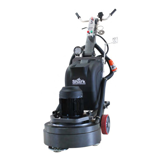
- Page 1 Shark S750 SAFETY & OPERATORS MANUAL CAUTION: Read the instruction manual before using. ...
-
Page 2: Table Of Contents
SHARK CONCRETE GRINDERS Table of Contents Specifications Page 3 Safety instructions Page 4-5 Operating instructions Page 6-7 Handle positions Page 8 Problem solving Page 9 Parts Diagram - Main Page 10 Parts List - Frame Page 11 Parts Diagram - Control Switch... -
Page 3: Specifications
SHARK CONCRETE GRINDERS Specifications Voltage 380-440 3 Phase, 32A Power 11KW, 15HP Working width 750mm Weight 340kg Extra weight 40kg Rotating speed 450-1950rpm Tool holder diameter 260mm x 3 Vacuum connector diameter 60mm Water tank capacity Packing 132 x 88 x 119... -
Page 4: Safety Instructions
SHARK CONCRETE GRINDERS Safety Instructions Read and understand the instructions of the machine in this manual and the engine manual (if applicable). Different models may have different parts and controls. Equipment should only be operated by trained personnel, in good physical condition and mental health (not fatigued). - Page 5 Never operate machine in rain or if heavy moisture is present. Do not operate the Shark S750 with any covers or doors removed or open. The Shark S750 can produce sound pressure levels greater than 85db.
-
Page 6: Operating Instructions
SHARK CONCRETE GRINDERS Operating Instructions Wear clothes suitable for the job and work place including; safety boots, hard hat, hearing protection, non-fogging vented safety goggles and a dust respirator. Ensure all equipment is tested and tagged prior to use on any job. - Page 7 It can be between the inverter output and the motor connection or inside the motor electric box. 24. All Shark grinders must have the gear oil changed after running 500 hours (2-3 months) for the first time, later each 1500 hours (5-6months). Gear oil - Castrol Universal 80W-90.
- Page 8 SHARK CONCRETE GRINDERS Handle Position STORAGE AND LIFTING MODE TOOLING MODE OPERATING MODE ...
-
Page 9: Problem Solving
SHARK CONCRETE GRINDERS Problem Solving Remedy Error Code Cause Ground fault protection circuit action. 1.Check if there is a short circuit When ac motor drives measure the output phenomenon or ground connection. Ground Fault ground and the grounding power is more 2.Confirm if IGBT power modules are... -
Page 10: Parts Diagram - Main
SHARK CONCRETE GRINDERS Parts Diagram - Main ... -
Page 11: Parts List - Frame
SHARK CONCRETE GRINDERS Parts Diagram - Frame ... -
Page 12: Parts Diagram - Control Switch
SHARK CONCRETE GRINDERS Parts Diagram - Control Switch ... -
Page 13: Parts Diagram - Frame
SHARK CONCRETE GRINDERS Parts Diagram - Frame ... -
Page 14: Parts Diagram - Wire Rack
SHARK CONCRETE GRINDERS Parts Diagram - Wire Rack ... -
Page 15: Parts Diagram - Frame Base
SHARK CONCRETE GRINDERS Parts Diagram - Frame Base ... -
Page 16: Parts Diagram - Wheel Base
SHARK CONCRETE GRINDERS Parts Diagram - Wheel Base ... -
Page 17: Parts Diagram - Inverter Hosing
SHARK CONCRETE GRINDERS Parts Diagram - Inverter Housing ... -
Page 18: Parts Diagram - Gearbox
SHARK CONCRETE GRINDERS Parts Diagram - Gearbox ... -
Page 19: Parts Diagram - Gearbox Housing
SHARK CONCRETE GRINDERS Parts Diagram - Gearbox Housing ... -
Page 20: Wiring Diagram
SHARK CONCRETE GRINDERS 3 Phase Wire Colours (4pin ) Active 1 = Red Active 2= Yellow Active 3 = Green Earth = Blue ... - Page 21 Below are the steps required to adjust the 3 grinding plates to the same horizontal surface. Take a tape measure, stand vertical along the plate to the gearbox, to measure the height from the gearbox bottom to the plate side. (Total needed to measure is 9, as there are each 3 screws on one plate. The height from gearbox bottom to the plate at the side of screws is what we need to measure) There may be different figures here at the 9 positions.