Table of Contents
Advertisement
Quick Links
Advertisement
Chapters
Table of Contents

Summary of Contents for Swann AMU Rescon
- Page 1 AMU Rescon Version 6.20 and higher A-96.250.351 / 230320...
- Page 2 For any technical question, contact your nearest SWAN representative, or the manufacturer: SWAN ANALYTISCHE INSTRUMENTE AG Studbachstrasse 13 8340 Hinwil Switzerland Internet: www.swan.ch E-mail: support@swan.ch Document Status AMU Rescon Operator’s Manual Title: A-96.250.351 Revision Issue March 2007 First Edition June 2019 Update to firmware V6.20 ©...
-
Page 3: Table Of Contents
Single Components ........2.2.1 AMU Rescon Transmitter ......2.2.2 Flow Cell QV-Flow and QV-HFlow SS316L 130 . - Page 4 AMU Rescon Operation ......... . .
-
Page 5: Safety Instructions
AMU Rescon Safety Instructions AMU Rescon–Operator’s Manual This document describes the main steps for instrument setup, oper- ation and maintenance. Safety Instructions General The instructions included in this section explain the potential risks associated with instrument operation and provide important safety practices designed to minimize these risks. -
Page 6: Warning Notices
AMU Rescon Safety Instructions 1.1. Warning Notices The symbols used for safety-related notices have the following sig- nificance: DANGER Your life or physical wellbeing are in serious danger if such warnings are ignored. Follow the prevention instructions carefully. WARNING Severe injuries or damage to the equipment can occur if such warnings are ignored. -
Page 7: General Safety Regulations
AMU Rescon Safety Instructions Warning Signs The importance of the warning signs in this manual. Electrical shock hazard Corrosive Harmful to health Flammable Warning general Attention general 1.2. General Safety Regulations Legal The user is responsible for proper system operation. -
Page 8: Restrictions For Use
1.3. Restrictions for use The AMU Rescon is designed for determination of specific conduc- tivity or resistivity in high purity water. To avoid clogging the flow cell, prevent sand, oil or solids, from en- tering into the flow cell. -
Page 9: Product Description
AMU Rescon Product Description Product Description 2.1. Description of the System This instrument is applicable for the determination of specific resis- tivity or specific conductivity in high purity water. Measuring The resistivity of high purity water is determined with a sensor con- sisting of two metal electrodes. - Page 10 AMU Rescon Product Description Input One input for potential-free contact to freeze the measuring value or to interrupt control in automated installations (hold function or re- mote-off). Communica- RS232 for logger download with HyperTerminal tion interface RS485 with Fieldbus protocol Modbus or Profibus DP (optional)
- Page 11 AMU Rescon Product Description The conductivity sensor RC-U [A] with integrated temperature sen- sor is screwed into the flow cell block [D]. The sample enters at the sample inlet [F]. It flows through the flow regulating valve [E], where the flow rate can be adjusted. Then the sample flows through the flow cell block [D] were the resistivity of the sample is measured.
-
Page 12: Single Components
AMU Rescon Product Description 2.2. Single Components 2.2.1 AMU Rescon Transmitter ® General Electronics housing: Noryl resin Protection degree: IP54 (front) Ambient temperature: -10 to +50 °C Humidity: 10–90% rel., non condensing Display: backlit LCD, 75 x 45 mm Dimensions:... -
Page 13: Flow Cell Qv-Flow And Qv-Hflow Ss316L 130
AMU Rescon Product Description 2.2.2 Flow Cell QV-Flow and QV-HFlow SS316L 130 Flow cell made of stainless steel with flow sensor for the connection to SWAN transmitter and with manual flow regulating valve. Con- nection to tube with Swagelok adapter. -
Page 14: Flow Cell B-Flow Ss316L 130
AMU Rescon Product Description 2.2.3 Flow Cell B-Flow SS316L 130 Flow cell made of stainless steel SS316L to connect to tubes. For one sensor with ¾" NPT thread, fitting length 89 mm. Technical data Sample inlet: Swagelok G 1/8” thread Sample outlet: Swagelok G 1/8”... -
Page 15: Swansensor Rc U
AMU Rescon Product Description 2.2.4 Swansensor RC U Sensor for the measurement of the specific conductivity and specif- ic resistivity in high purity water. 156 89 231 89 Swansensor RC U Swansensor RC U with integrated cable with Plug Specifications Measuring range: 0.055–1000 S/cm... -
Page 16: Installation
AMU Rescon Installation Installation 3.1. Installation Checklist Instrument’s specification must conform to your power ratings. Check Do not switch on power until all external devices are connected. The transmitter is intended for panel mounting. The dimensions Installation are shown under Dimensions of the AMU Transmitter, p. -
Page 17: Dimensions Of The Amu Transmitter
AMU Rescon Installation 3.2. Dimensions of the AMU Transmitter A-96.250.351 / 230320... -
Page 18: Connecting Sample Inlet And Outlet
AMU Rescon Installation 3.3. Connecting Sample Inlet and Outlet 3.3.1 Sample Inlet Preparation For the sample inlet a stainless steel tube is connected to the Swa- gelok fitting at the flow cell. Cut the tube to length and deburr it. The tube must be straight and free from blemishes for approximately 1,5 x tube diameter from the end. -
Page 19: Install Sensor Rcu
AMU Rescon Installation 3.4. Install Sensor RCU The following instruction applies for all flow cells and pipe flanges. To install the sensor RC U into a flow cell or a pipe flange proceed as follows: Install Sensor Teflon tape into Flow Cell... - Page 20 AMU Rescon Installation Installation examples for tube installation Sensor Tube Flange Flow direction Air vent hole Sensor Flange Air vent hole Flow direction Tube 1 Wrap 7 turns of teflon tape around the sensor thread. 2 Screw the sensor into the flow cell or the pipe flange.
-
Page 21: Electrical Connection
AMU Rescon Installation 3.5. Electrical Connection CAUTION Use only the terminals shown in this diagram, and only for the mentioned purpose. Use of any other terminals will cause short circuits with possible corresponding consequences to material and personnel. A-96.250.351 / 230320... - Page 22 AMU Rescon Installation Rear view of AMU Transmitter (+) (-) 2 3 4 5 6 7 8 9 10 11 12 13 14 RS232 RON OFF A/PB B/PB A-96.250.351 / 230320...
-
Page 23: Power Supply
FV1 Mains equipped with an external switch or circuit-breaker – near the instrument – easily accessible to the operator – marked as interrupter for AMU Rescon 3.7. Sensor Connect the sensor to the AMU transmitter according to the con- nection diagram, see Electrical Connection, p. -
Page 24: 3.10. Relay Contacts
AMU Rescon Installation 3.10. Relay Contacts 3.10.1 Alarm Relay NOTICE: Max. load 100 mA/50 V Alarm output for system errors. Error codes see Error List, p. Terminals Description Active (opened) during normal operation. Normally Closed Inactive (closed) on error and loss of power. -
Page 25: 3.12. Interfaces
AMU Rescon Installation 3.12. Interfaces 3.12.1 RS232 Interface The RS232 interface is located on the back of the AMU transmitter. The RS232 interface is used for logger download and firmware up- load. 3.12.2 Profibus (optional) To connect several instruments by means of a network or to config- ure a PROFIBUS DP connection, consult the PROFIBUS manual. -
Page 26: Modbus (Optional)
AMU Rescon Installation 3.12.3 Modbus (optional) To connect several instruments by means of a network consult the MODBUS manual. Use appropriate network cable. NOTICE: The switch must be ON if only one instrument is installed, or on the last instrument in the bus... -
Page 27: Instrument Setup
AMU Rescon Instrument Setup Instrument Setup 4.1. Establish Sample Flow 1 Open the flow regulating valve. 2 Wait until the flow cell is completely filled. 3 Switch on power. NOTICE: To allow a precise measurement in the range between 18 –18.18 MΩ, set the sample flow to 70–100 l/h. - Page 28 AMU Rescon Instrument Setup USP Operating Menu 5.1.3 Mode The USP Operating Mode implemented in the firmware of the AMU Rescon transmitter allows the measurement of pharmaceutical wa- ter according to the USP <645>. If the USP Operating Mode is set to <off> conductivity or resistivity standard measurement is performed.
-
Page 29: Operation
AMU Rescon Operation Operation 5.1. Keys Exit Enter to exit a menu or command (rejecting any changes) to move back to the previous menu level to move DOWN in a menu list and to decrease digits to move UP in a menu list and to increase digits... -
Page 30: Display
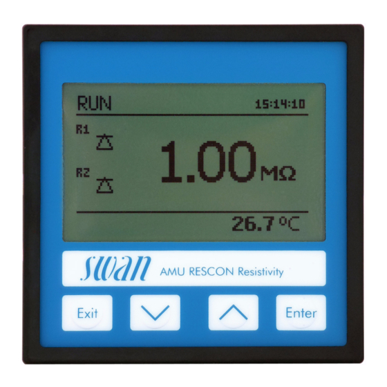
AMU Rescon Operation 5.2. Display 15:20:18 17.98 MΩ 80.0 l/h 24.8°C normal operation HOLD input closed or cal delay: Instrument on hold (shows status of signal outputs). input closed: control/limit is interrupted (shows status of signal outputs). ERROR Error Fatal Error... -
Page 31: Software Structure
AMU Rescon Operation 5.3. Software Structure Main Menu Messages Diagnostics Maintenance Operation Installation Menu Messages 1 Messages Reveals pending errors as well as an event history Pending Errors (time and state of events that have occurred at an Message List earlier point of time). -
Page 32: Changing Parameters And Values
AMU Rescon Operation 5.4. Changing Parameters and values Changing The following example shows how to set the Q-Hflow sensor: parameters 1 Select the parameter you want to Sensors 5.1.1 change. Flow None 2 Press [Enter] Meas. Mode Resistivity USP Operating Mode Sensor parameters Temp. -
Page 33: Maintenance
AMU Rescon Maintenance Maintenance 6.1. Maintenance Table If necessary Clean sensor According to Perform a transmitter check USP regulations 6.2. Stop of Operation for Maintenance WARNING Electrical shock hazard! Do not carry out maintenance work during normal operation. Always turn off power before manipulating electric parts. -
Page 34: Maintenance Of Sensor
AMU Rescon Maintenance 6.3. Maintenance of Sensor 6.3.1 Clean Sensor The Swansensor RC-U is largely maintenance free. However, de- pending on the application, it can be contaminated, which may cause problems. The Swansensor RC-U is available in the following 2 different ver- sions: ... - Page 35 AMU Rescon Maintenance Sensor Flow cell Flow regulating valve Install the 1 Wrap 7 turns of teflon tape around the sensor thread. sensor with fix 2 Screw the sensor into the flow cell and tighten it well. cable 3 Feed the sensor cable into the transmitter housing.
- Page 36 AMU Rescon Maintenance Remove the 1 Unscrew and remove the sensor plug [A] from the sensor [B]. sensor with 2 Proceed according to “Remove the Sensor with fixed cable”, plug step 4. Sensor plug Sensor Install the sen- 1 Wrap 7 turns of teflon tape around the sensor thread.
-
Page 37: Conductivity-Resistivity Qc-Kit Test Plug
Test mode For a quick and easy test, the AMU Rescon transmitter has the test mode <Transmitter check> that enables testing without changing any of these values. When leaving the test mode, all parameters will be set back to their original value. -
Page 38: Carry Out A Transmitter Check
AMU Rescon Maintenance 6.4.2 Carry out a transmitter check Sensor plug Test resistor Sensor RC U Connect the 1 Unscrew and remove the sensor plug [A] from the sensor [C] test resistor 2 Screw the sensor plug onto the test resistor [B]. -
Page 39: Fine Adjust
6.5. Fine Adjust The function fine adjust is only available if the AMU Rescon is set to the measuring mode resistivity. The function “Fine Adjust” is performed automatically every night at 00:30 h. -
Page 40: Longer Stop Of Operation
AMU Rescon Maintenance 6.6. Longer Stop of Operation 1 Stop sample flow. 2 Shut off power of the instrument. 3 Unscrew and remove the sensor. 4 Empty and dry the flow cell A-96.250.351 / 230320... -
Page 41: Error List
AMU Rescon Error List Error List Error Non-fatal Error. Indicates an alarm if a programmed value is ex- ceeded. Such Errors are marked E0xx (bold and black). Fatal Error (blinking symbol) Control of dosing devices is interrupted. The indicated measured values are possibly incorrect. - Page 42 AMU Rescon Error List Error Description Corrective action – check process E001 Alarm high – check programmed value – check process E002 Alarm low – check programmed value – check process E007 Sample Temp. high – check programmed value – check process E008 Sample Temp.
- Page 43 AMU Rescon Error List Error Description Corrective action – call service E026 IC LM75 – call service E030 EEProm Frontend – call service E031 Calibration Recout – call service E032 Wrong Frontend – none, normal status E033 Power-on – none, normal status...
-
Page 44: Program Overview
AMU Rescon Program Overview Program Overview For explanations about each parameter of the menus see Program List and Explanations, S. Menu 1 Messages informs about pending errors and mainte- nance tasks and shows the error history. Password protection possible. No settings can be modified. -
Page 45: Diagnostics (Main Menu 2)
AMU Rescon Program Overview 8.2. Diagnostics (Main Menu 2) Identification Designation AMU Rescon * Menu numbers 2.1* Version V6.20-11/16 Factory Test 2.1.3.1* Instrument 2.1.3* Motherboard Front End Operating Time 2.1.4.1* Years / Days / Hours / Minutes / Seconds 2.1.4* Sensors Cond. -
Page 46: Maintenance (Main Menu 3)
AMU Rescon Program Overview 8.3. Maintenance (Main Menu 3) Simulation 3.2.1* * Menu numbers Alarm Relay 3.1* 3.2.2* Relay 1 3.2.3* Relay 2 Signal Output 1 3.2.4* 3.2.5* Signal Output 2 Set Time (Date), (Time) 3.2* Transmitter check 3.3* Fine adjust Current Value 3.5.1*... -
Page 47: Installation (Main Menu 5)
AMU Rescon Program Overview 8.5. Installation (Main Menu 5) Sensors * Menu numbers Flow 5.1* 5.1.1* Meas. Mode 5.1.2* USP Operating Mode 5.1.3 Sensor Parameters Cell Constant 5.1.4 Temp. Corr. Cable length Temp. Compensation Comp. 5.1.5.1 5.1.5* Signal Outputs Signal Output 1 and 2 5.2.1.1 - 5.2.2.1*... -
Page 48: Delay
AMU Rescon Program Overview Input Active 5.3.4.1* * Menu numbers 5.3.4* 5.3.4.2* Signal Outputs 5.3.4.3* Output/Control 5.3.4.4* Fault 5.3.4.5* Delay Miscellaneous Language 5.4.1* 5.4* 5.4.2* Set defaults 5.4.3* Load Firmware Password 5.4.4.1* Messages 5.4.4* 5.4.4.2* Maintenance Operation 5.4.4.3* Installation 5.4.4.4* 5.4.5*... -
Page 49: Program List And Explanations
AMU Rescon Program List and Explanations Program List and Explanations 1 Messages 1.1 Pending Errors 1.1.5 Provides the list of active errors with their status (active, acknowl- edged). If an active error is acknowledged, the alarm relay is active again. Cleared errors are moved to the Message list. -
Page 50: Maintenance
AMU Rescon Program List and Explanations 2.2.2 Miscellaneous: 2.2.2.1 Case Temp: Shows the actual temperature in °C inside the trans- mitter. 2.3 Sample 2.3.1 Sample ID: Shows the assigned sample identification. This identification is defined by the user to identify the location of the sample Temperature: Shows temperature in °C. -
Page 51: Operation
United States Pharmacopeia (USP). See Conductivity-Resistivity QC-Kit Test Plug, p. 3.5 Fine adjust The function fine adjust is only available if the AMU Rescon is set to the measuring mode resistivity. The function “fine adjust” performs an internal resistor adjustment. 4 Operation 4.1 Sensors... -
Page 52: Installation
AMU Rescon Program List and Explanations 4.3 Logger The instrument is equipped with an internal logger. The logger data can be downloaded to a PC using the built-in RS232 interface. The logger can save approx. 1500 data records. The Records con- sists of: Date, time, alarms, measuring value, raw value (MΩ), case... - Page 53 AMU Rescon Program List and Explanations 5.1.3 USP Operating Mode: Switch the USP Operating Mode on or off (see USP Operating Mode, p. 5.1.4 Sensor parameters: 5.1.4.1 Cell Constant: Enter the cell constant ZK printed on the label of the sensor (see Sensor Parameters, p.
- Page 54 AMU Rescon Program List and Explanations 5.2.1.3 Function: Define if the signal output is used to transmit a process value or to drive a control unit. Available functions are: Linear, bilinear or logarithmic for process values. As process values, p. 52 ...
- Page 55 AMU Rescon Program List and Explanations 5.2.1.40.10 Range low: 0.00–200 MΩ or 0.000–2000 S 5.2.1.40.20 Range high: 0.00–200 MΩ or 0.000–2000 S If Parameter = Temperature 5.2.1.40.11 Range low: -30.0 to +130 °C 5.2.1.40.21 Range high: -30.0 to +130 °C If Parameter = Sample flow 5.2.1.40.12...
- Page 56 AMU Rescon Program List and Explanations Response to maximum control output = 1.2/a Tangent on the inflection point = 2L Time = L/2 The point of intersection of the tangent with the respective axis will result in the parameters a and L.
- Page 57 AMU Rescon Program List and Explanations 5.2.1.43.3 Reset time: The reset time is the time till the step response of a sin- gle I-controller will reach the same value as it will be suddenly reached by a P-controller. Range: 0–9’000 sec 5.2.1.43.4...
- Page 58 AMU Rescon Program List and Explanations 5.3.1.1.36 Hysteresis: Within the hyst. range, the relay does not switch. This prevents damage of relays contacts when the measured value fluc- tuates around the alarm value. Range. 0.000–2000 S or 0.00–200 M 5.3.1.1.46...
- Page 59 AMU Rescon Program List and Explanations 5.3.2 and 5.3.3 Relay 1 and 2: The function of relay contacts 1 or 2 are defined by the user. NOTICE: The navigation in the menu <Relay 1> and <Relay 2> is identical. For reason of simplicity only the menu numbers of Relay 1 are used in the following.
- Page 60 AMU Rescon Program List and Explanations 5.3.2.50 Delay: Duration, the activation of the alarm relay is retarded after the measuring value has risen above/fallen below the programmed alarm. Range. 0–600 Sec 5.3.2.1 Function = Control upwards/downwards: The relays may be used to drive control units such as solenoid valves, membrane dosing pumps or motor valves.
- Page 61 AMU Rescon Program List and Explanations Actuator = Motor valve Dosing is controlled by the position of a motor driven mixing valve. 5.3.2.32.22 Run time: Time needed to open a completely closed valve Range: 5–300 Sec. 5.3.2.32.32 Neutral zone: Minimal response time in % of the runtime. If the re- quested dosing output is smaller than the response time, no change will take place.
- Page 62 AMU Rescon Program List and Explanations 5.3.2.7 Output/Control: Select operating mode of the controller output: Cont.: Controller continues normally. Controller continues based on the last valid value. Hold: Controller is switched off. Off: 5.3.2.24 daily The relay contact can be activated daily, at any time of a day.
- Page 63 AMU Rescon Program List and Explanations 5.3.2.1 Function = Fieldbus The relay will be switched via the Profibus input. No further param- eters are needed. 5.3.4 Input: The functions of the relays and signal outputs can be de- fined depending on the position of the input contact, i.e. no function, closed or open.
- Page 64 AMU Rescon Program List and Explanations 5.4 Miscellaneous 5.4.1 Language: Set the desired language. Language German English French Spanish 5.4.2 Set defaults: Reset the instrument to factory default values in three different ways: Set defaults Calibration In parts Completely Calibration: Sets calibration values back to default. All other values are kept in memory.
- Page 65 AMU Rescon Program List and Explanations 5.5 Interface Select one of the following communication protocols. Depending on your selection, different parameters must be defined. 5.5.1 Protocol: Profibus 5.5.20 Device address: Range: 0–126 5.5.30 ID-Nr.: Range: Analyzer; Manufacturer; Multivariable 5.5.40 Local operation: Range: Enabled, Disabled 5.5.1...
-
Page 66: Default Values
AMU Rescon Default Values Default Values NOTICE: The AMU Rescon has two different measuring modes (Resistivity or Conductivity) which can be set in menu <Installation>/<Sensors>/<Meas. Mode>. The instrument remains in the selected operating mode even after the <Default Values> are reset completely. Therefore, this default value list is divided in the two parts Resistivity and Conductivity where necessary. - Page 67 AMU Rescon Default Values Scaling: Range low:..............0.0 °C Scaling: Range high: ............50.0 °C Alarm Relay: Alarm: Alarm high: ................200 MΩ Resistivity Alarm low:................0.00 MΩ Hysteresis:................1.00 MΩ Alarm high: ................2000 µS Conductivity Alarm low:................0.000 µS Hysteresis:................10.00 µS...
- Page 68 AMU Rescon Default Values Settings: Pulse Frequency: ..........120/min Settings: Control Parameters: Setpoint: ......25.0 l/h Settings: Control Parameters: P-band:........1 l/h Settings: Control Parameters: Reset time: ....... 0 s Settings: Control Parameters: Derivative Time: ....... 0 s Settings: Control Parameters: Control Timeout:....0 min Settings: Actuator:..........
-
Page 69: Index
AMU Rescon Index Index ..Alarm Relay Longer Stop of Operation ..... . . -
Page 70: Notes
AMU Rescon Notes Notes A-96.250.351 / 230320... - Page 71 AMU Rescon Notes A-96.250.351 / 230320...
- Page 72 AMU Rescon SWAN is represented worldwide by subsidiary companies and distributors. cooperates with independent representatives all over the world. SWAN Products Analytical Instruments for: High Purity Water Feedwater, Steam and Condensate Potable Water Pool and Sanitary Water Cooling Water Waste Water and Effluents Made in Switzerland A-96.250.351 / 230320...