Table of Contents
Advertisement
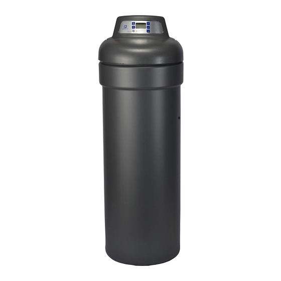
Model NSCWC
How to install, operate
and maintain your Demand
Controlled Water Conditioner
If you have any questions or concerns when
installing, operating or maintaining your
water softener, contact us at:
info@northstarwater.com
www.northstarwater.com
or visit
System tested and certified by NSF International
against NSF/ANSI Standard 42 for the reduction
of chlorine taste and odor, and Standard 44
for hardness reduction, efficiency and the
reduction of barium and radium 226/228,
and certified to NSF/ANSI Standard 372.
System tested and certified by the
Water Quality Association against CSA B483.1.
Designed, Engineered &
Assembled in the U.S.A.
Manufactured and warranted by
North Star Water Treatment Systems
1890 Woodlane Drive
Woodbury, MN 55125
7371389 (Rev. A 6/11/18)
Advertisement
Table of Contents

Related Manuals for North Star NSCWC

Summary of Contents for North Star NSCWC
- Page 1 NSF/ANSI Standard 372. System tested and certified by the Water Quality Association against CSA B483.1. Manufactured and warranted by North Star Water Treatment Systems Designed, Engineered & 1890 Woodlane Drive 7371389 (Rev. A 6/11/18) Assembled in the U.S.A.
-
Page 2: Table Of Contents
TABLE OF CONTENTS Page Specifications & Performance Claims ............2-3 Dimensions . -
Page 3: Specifications & Performance Claims
Specifications & Performance Claims SPECIFICATIONS Model NSCWC Model Code nSAC 14,000 @ 2.9 lbs. Rated Softening Capacity (Grains @ Salt Dose) 29,800 @ 9.3 lbs. 35,600 @ 15.6 lbs. Rated Efficiency (Grains/Pound of Salt @ Minimum Salt Dose) 4,780 @ 2.9 lbs. -
Page 4: Dimensions
Dimensions 16-1/2” 16-1/2" 3-3/8” 3-3/8" 19-3/4” 19-3/4" IN – OUT IN - OUT 47-3/4” 47-3/4" 41-1/2” 40-1/4” 41-1/2" 40-1/4" FIG. 1 FRONT VIEW SIDE VIEW FRONT VIEW SIDE VIEW Before You Start The water softener requires a minimum water flow of 3 gallons per minute at the inlet. Maximum allowable inlet water pressure is 125 psi. -
Page 5: Inspect Shipment
Inspect Shipment The parts required to assemble and install the water Remove and discard (or recycle) all packing materials. softener are included with the unit. Thoroughly check To avoid loss of small parts, we suggest you keep the the water softener for possible shipping damage and small parts in the parts bag until you are ready to use parts loss. -
Page 6: Installation Requirements
Installation Requirements LOCATION REQUIREMENTS PLUMBING CODES Consider all of the following when selecting an installa- All plumbing must be completed in accordance with tion location for the water softener. national, state and local plumbing codes. Do not locate the water softener where freezing In the state of Massachusetts: The Commonwealth temperatures occur. - Page 7 Installation Requirements VALVE DRAIN REQUIREMENTS 1/4” NPT Thread Barbs for 3/8” Using the flexible drain hose (included), measure and I.D. Tubing cut to the length needed. Flexible drain hose is not Hose Clamp allowed in all localities (check your plumbing codes). If local codes do not allow use of a flexible drain hose, a Drain Hose rigid valve drain run must be used.
-
Page 8: Installation Instructions
ASSEMBLY 3. Make sure the turbine assembly spins freely in the 1. North Star models are factory assembled. During "out" port of the valve (See Figure 10). installation, unsnap and remove the top cover, 4. - Page 9 Installation Instructions COMPLETE INLET AND OUTLET PLUMBING Top Cover Nozzle & Venturi Assembly Measure, cut, and loosely assemble pipe and fittings from the main water pipe to the inlet and outlet ports of the water softener valve. Be sure to keep fittings fully Salt Lid together, and pipes squared and straight.
- Page 10 Installation Instructions COLD WATER PIPE GROUNDING INSTALL SALT STORAGE TANK OVERFLOW HOSE CAUTION: The house cold water pipe (metal only) is often used as a ground for the house 1. Measure, cut to needed length and connect the 3/8” electrical system, The 3-valve bypass drain line (provided) to the salt storage tank overflow type of installation, shown in Figure 8, elbow and secure in place with a hose clamp.
- Page 11 Installation Instructions RINSE OUT CARBON FINES SANITIZE THE WATER SOFTENER / SANITIZE AFTER SERVICE Small particles of carbon filtration material are generat- ed during manufacturing and shipping, which will exit Care is taken at the factory to keep your unit clean and the media tank with the first water flow.
- Page 12 Installation Instructions TEST FOR LEAKS To check for leaks, complete the following steps: If removing 1. Fully open two nearby cold water faucets down- clips... stream from the water softener. 2. Observe steady flow from both faucets. 3. After about three minutes, open a hot water faucet for about one minute, or until all air is expelled, and ...depressurize the then close this faucet.
-
Page 13: Programming The Water Softener
Programming the Water Softener SET SALT LEVEL button Display UP button SELECT button TANK LIGHT button SALT SALT LEVEL ALARM Salt Level Tank Select Light Recharge Press for tonight LOW SALT Hold for immediate FIG. 16 RECHARGE button LOW SALT indicator DOWN button PROGRAM THE SOFTENER SET PRESENT TIME OF DAY... - Page 14 Programming the Water Softener SET WATER HARDNESS NUMBER SET RECHARGE (REGENERATION) START TIME If you completed the previous step, the word “HARD - If you completed the previous step, the words “RE - NESS" should show in the display. Otherwise, press CHARGE TIME"...
-
Page 15: Controller Features
Controller Features EXTRA RECHARGE SALT MONITOR SYSTEM Sometimes, a manually initiated recharge (regenera- The water softener has a salt monitor indicator light to tion) may be desired, or needed. Two examples are: remind you to add salt to the storage tank. NOTE: You must set salt level each time salt is You have used more water than usual (guests visit- ing) and you may run out of soft water before the... - Page 16 DOWN button to shorten the time. If no change is California Efficiency Requirement desired, continue to next step. Your North Star Water Softener has a “High continued on next page Efficiency” feature that can be set ON or OFF. This softener is shipped with the efficiency fea-...
- Page 17 Controller Features 4. Press SELECT again to display the “Recharge 6. Press SELECT again to display the “12 or 24 hr” Days” screen. screen. FIG. 31 Default Display Example: Set to 4 days maxi mum between regenerations 12 OR 24 HOUR CLOCK: All time displays are shown in standard clock time (1 to 12 AM;...
- Page 18 Controller Features TANK LIGHT POWER OUTAGE MEMORY To turn on the light inside the salt storage tank, press If electrical power to the softener is interrupted, the the TANK LIGHT button on the faceplate. Press this time display is blank but the electronic controller button again to turn the light off.
-
Page 19: Routine Maintenance
Routine Maintenance ADDING SALT BREAKING A SALT BRIDGE Sometimes, a hard crust or salt “bridge” forms in the Lift the salt lid and check the salt storage level fre- brine tank. It is usually caused by high humidity or quently. If the water softener uses all the salts before the wrong kind of salt. - Page 20 Routine Maintenance CLEANING THE NOZZLE & VENTURI PROTECT THE WATER SOFTENER FROM FREEZING A clean nozzle & venturi (See Figure 38) is a necessity for the water softener to work properly. This small If the softener is installed where it could freeze (sum- component creates the suction to move brine from the mer cabin, lake home, etc.), you must drain all water brine tank, into the resin tank.
- Page 21 Troubleshooting Guide PROBLEM CAUSE CORRECTION No soft water 1. No salt in the storage tank. Refill with salt and then use RECHARGE NOW feature. No soft water & dis- 1. Power supply unplugged at wall outlet, or Check for loss of power and correct. Reset electronic play is blank power cable disconnected from back of elec - controls and then use RECHARGE NOW feature.
-
Page 22: Troubleshooting
Troubleshooting MANUALLY INITIATED ELECTRONIC DIAGNOSTICS 1. To enter diagnostics, press the SELECT button and hold for three seconds. The display will change to Motor show turbine count, valve cycle position, and posi- Position tion switch status (open or closed). Switch Turbine Count Valve Position Turbine Count... -
Page 23: Wiring Schematic
Troubleshooting MANUAL ADVANCE REGENERATION CHECK This check verifies proper operation of the valve Position Markers motor, brine tank fill, brine draw, regeneration flow (valve in service) rates, and other controller functions. Always make the initial checks first, and perform the manually initi- ated electronic diagnostics. -
Page 24: Exploded View & Parts List
Softener Exploded View Valve Assembly See Pages 26- 27 for parts Rating Decal Location... - Page 25 Rim Insert (for shipping only) Adaptor Elbow 7139999 Drain Hose Grommet 7371389 Owner’s Manual ¢ Hose Clamp Not illustrated. ¢ To order repair parts, contact us at: info@northstarwater.com Manufactured and warranted by North Star Water Treatment Systems 1890 Woodlane Drive Woodbury, MN 55125...
- Page 26 Valve Exploded View Wear Strip Seal Cross-section View...
- Page 27 Bypass Valve Assembly, 3/4”, in - 7342657 Screw, #10-14 x 2”, pack of 5 7370286 cluding 2 O-Rings (See Key No. 72) To order repair parts, contact us at: info@northstarwater.com Manufactured and warranted by North Star Water Treatment Systems 1890 Woodlane Drive Woodbury, MN 55125...
-
Page 28: Warranty
WATER CONDITIONER WARRANTY Warrantor: North Star Water Treatment Systems, 1890 Woodlane Drive, Woodbury, MN 55125 Warrantor guarantees, to the original owner, that: One Year Full Warranty: ● For a period of one (1) year from the date of purchase, all parts will be free from defects in materials and workman- ship and will perform their normal functions.