
Related Manuals for Extreme Networks AP-7532

Summary of Contents for Extreme Networks AP-7532
- Page 1 AP-7532 Access Point Installation Guide Published June 2017 9035112 9035112 Published June 2017 9035112...
- Page 2 Copyright © 2017 Extreme Networks, Inc. All Rights Reserved. Legal Notices Extreme Networks, Inc. reserves the right to make changes in specifications and other information contained in this document and its website without prior notice. The reader should in all cases consult representatives of Extreme Networks to determine whether any such changes have been made.
-
Page 3: Table Of Contents
AP-7532 Package Contents ............................4 Features ......................................4 AP-7532 Antennas ................................4 AP-7532 Dual Band 2.4 GHz / 5 GHz Antennas - US ....................4 AP-7532 Dual Band 2.4 GHz / 5 GHz Antennas - EMEA ....................5 AP-7532 Internal Antenna Model ............................5 AP-7532 Dual Band 2.4 GHz / 5 GHz Antennas - Canada .................. - Page 4 Korea Warning Statement for Class B ITE ......................36 Other Countries ................................36 Waste Electrical and Electronic Equipment (WEEE) ..................38 TURKISH WEEE Statement of Compliance ......................39 End-User License Agreement................41 AP-7532 Access Point China ROHS Compliance..........47 AP-7532 Access Point Installation Guide...
-
Page 5: Introduction
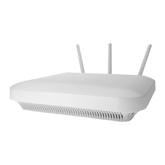
Point’s with a relatively small footprint which supports functionality for dependable and efficient network performance.The AP-7532 is a 3x3:3 802.11ac Access Point utilizing one 2.4 GHz 802.11n radio and one 5 GHz 802.11ac radio. The Access Point housing is Plenum-rated (UL2043). -
Page 6: Site Preparation
• Verify cable lengths are within the maximum allowable distances for optimal signal transmission. AP-7532 Package Contents An AP-7532 Access Point is available in both external antenna (AP-7532) and internal antenna (AP-7532I) configurations. An AP-7532 ships with the following: • AP-7532 Access Point •... -
Page 7: Ap-7532 Dual Band 2.4 Ghz / 5 Ghz Antennas - Emea
ML-2452-VMM5M3- Patch * This antenna is for indoor placement only. AP-7532 Dual Band 2.4 GHz / 5 GHz Antennas - EMEA An external antenna AP-7532 supports the following dual band antenna options for the EMEA: Part Number Antenna Type 2.4 GHZ Gain (dBi) -
Page 8: Ap-7532 Dual Band 2.4 Ghz / 5 Ghz Antennas - Canada
5 GHZ Gain (dBi) PIFA 4.13 5.92 AP-7532 Dual Band 2.4 GHz / 5 GHz Antennas - Canada *An external antenna AP-7532 supports the following dual band antenna options for Canada: Part Number Antenna Type 2.4 GHZ Gain (dBi) 5 GHZ Gain (dBi) -
Page 9: Hardware Installation
Hardware Installation An AP-7532 Access Point mounts either on a wall (with M 3.5 x 0.6 x 23 MM pan head screws and mounting bracket- or equivalent) or on a suspended ceiling T-bar. To prepare for the installation: 1 Match the part number on the purchase order with the part numbers in the packing list and on the case of the Access Point. -
Page 10: Access Point Placement
Access Point. Power Injector System An AP-7532 Access Point can receive power via an Ethernet cable connected to the GE1/ POE (LAN) port. When users purchase a WLAN solution, they often need to place Access Points in obscure locations. - Page 11 Access Point and void the product warranty.. A separate Power Injector is required for each AP-7532 Access Point comprising the network. The Power Injector can be installed free standing, on an even horizontal surface or wall mounted using the power injector’s wall mounting key holes.
-
Page 12: Wall Mount Instructions
Wall Mount Instructions A wall mount deployment requires hanging the AP-7532 Access Point with the provided mounting bracket and two screws. The AP-7532 can be mounted on to any plaster, wood or cement wall surface using the provided mounting bracket. -
Page 13: Wall Mount Procedure - New Installation
Hardware Installation Wall Mount Procedure - New Installation This section describes a new AP-7532 installation with no previous Access Point existing on the intended wall surface. 1 Place the mounting bracket against the wall. 2 Mark the screw hole locations depending on the intended deployment orientation of the unit. -
Page 14: Wall Mount Procedure - Existing Access Point Replacement
Ceiling mount requires holding the AP-7532 up against a T-bar of a suspended ceiling grid and twisting the unit on to the T-bar. If deploying the AP-7532 on a sculpted ceiling T-Bar, the Access Point mounting kit (Part No. KT-135628-01) can optionally be used as well. - Page 15 Access Point. 2 Cable the Access Point using either the Power Injector solution (AP-PSBIAS-2P3-ATR) or the approved AP-7532 power supply (PWRS-14000-54R). For Power Injector installations: a Connect a RJ-45 CAT5e (or CAT6) Ethernet cable between the network data supply (host) and the Power Injector Data In connector.
- Page 16 Do not actually connect to the power source until the cabling portion of the installation is complete.. 3 Verify the unit has power by observing the LEDs. For more information on AP-7532 LED behavior, see “LED Indicator” on page 15.
-
Page 17: Led Indicator
Hardware Installation The Access Point is ready to configure. LED Indicator The AP-7532 LED activity indicators are located on the front of the housing and are visible through the enclosure. AP-7532 Access Point Installation Guide... - Page 18 Hardware Installation The LEDs provide a status display indicating error conditions, transmission, and network activity for the 5 GHz 802.11ac (amber) radio and the 2.4 GHz 802.11n (green) radio. AP-7532 Access Point Installation Guide...
- Page 19 This LED state in rate. This LED state in no way resembles no way resembles normal operating normal operating conditions. conditions AP-7532 Access Point Installation Guide...
- Page 20 Hardware Installation AP-7532 Access Point Installation Guide...
-
Page 21: Basic Access Point Configuration
Basic Access Point Configuration Once the AP-7532 is installed and powered on, complete the following steps to get the Access Point up and running and access management functions: 1 The Access Point’s IP address is optimally provided using DHCP or from bottom of the Access Point itself (if available). - Page 22 • Country Code - If the Country Code was not set when the Access Point was initially powered on, set the country now to ensure the Access Point’s legal operation. The Access Point’s wireless capabilities are disabled until the required country code is set. AP-7532 Access Point Installation Guide...
- Page 23 IP address for the Access Point’s WAN connection. Manually provide the Access Point’s Static IP/Mask and Default Gateway. • PPPoE Settings - Optionally enable Point-to-Point Protocol over Ethernet (PPPoE) on the WAN network. If PPPoE is enabled, provide the required Auth Type, Login Name AP-7532 Access Point Installation Guide...
- Page 24 DHCP (within the Configuration > Services screen) for client IP address requests and ensuring routable traffic. 14 Select Apply to commit the updates to the selected Access Point’s configuration. 15 Expand the Configuration menu item and select Wireless. AP-7532 Access Point Installation Guide...
- Page 25 In respect to Wireless LAN settings, at minimum, a WLAN should be created providing some measure of security. 16 To create a new WLAN, select + Add from the upper, left-hand side of the Wireless LAN field. AP-7532 Access Point Installation Guide...
- Page 26 Controller AP, both radio bands should be enabled. • VLAN - Use the spinner control to specify a VLAN from 1 - 4,094 for this WLAN. When a client associates with a WLAN, the client is assigned a VLAN by load balance AP-7532 Access Point Installation Guide...
- Page 27 23 At this point, you’re ready to connect to the network using the security restrictions applied to the newly created WLAN. Ensure the new secure WLAN has been enabled, and check whether a client is able to access the network. AP-7532 Access Point Installation Guide...
- Page 28 Basic Access Point Configuration AP-7532 Access Point Installation Guide...
-
Page 29: Ap-7532 Access Point Specifications
AP-7532 Access Point Specifications Electrical Characteristics An AP-7532 Access Point has the following electrical characteristics: Operating Current & Voltage 12VDC, 1.25A (AUX input voltage) 12VDC PWRS-14000-54R power supply 48VDC, 0.375A (POE) 802.3at AP-PSBIAS-2P3- ATR Power Injector Physical Characteristics An AP-7532 Access Point has the following physical characteristics: Dimensions 7.1 in. -
Page 30: Radio Characteristics
AP-7532 Access Point Specifications Radio Characteristics The AP-7532 Access Point has the following radio characteristics: Data Rates Supported 802.11b/g: 1,2,5.5,11,6,9,12,18,24,36,48 and 54 Mbps 802.11a: 6,9,12,18,24,36,48, and 54 Mbps 802.11n: MCS 0-23 up to 450 Mbps 802.11ac: MCS 0-9 up to 1.3 Gbps... -
Page 31: Regulatory Information
Regulatory Information This guide applies to the following Model Numbers: AP-7532, AP-7532I. Extreme Networks devices are designed to be compliant with rules and regulations in locations they are sold and will be labeled as required. Any changes or modifications to Symbol equipment, not expressly approved by Extreme Networks could void the user's authority to operate the equipment. -
Page 32: Country Selection
• Reduce or eliminate repetitive motion • Maintain a natural position • Reduce or eliminate excessive force • Keep objects that are used frequently within easy reach AP-7532 Access Point Installation Guide... -
Page 33: Warnings For The Use Of Wireless Devices
Safety in Hospitals Wireless devices transmit radio frequency energy and may affect medical electrical equipment. When installed adjacent to other equipment, it is advised to verify that the adjacent equipment is not adversely affected. Pacemakers AP-7532 Access Point Installation Guide... -
Page 34: Rf Exposure Guidelines
Co-located statement To comply with FCC RF exposure compliance requirements, the antenna used for this transmitter must not be co-located or operating in conjunction with any other transmitter/ antenna except those already approved in this filling. AP-7532 Access Point Installation Guide... -
Page 35: Power Supply
This equipment generates, uses and can radiate radio frequency energy and, if not installed and used in accordance with the instructions, may cause harmful interference to radio communications. AP-7532 Access Point Installation Guide... -
Page 36: Radio Transmitters (Part 15)
Conformément à la réglementation d'Industrie Canada, le présent émetteur radio peut fonctionner avec une antenne d'un type et d'un gain maximal (ou inférieur) approuvé pour l'émetteur par Industrie Canada. Dans le but de réduire les risques de brouillage AP-7532 Access Point Installation Guide... -
Page 37: Ce Marking And European Economic Area (Eea)
Refer to “AP-7532 Antennas” on page 4 for a listing of the 2.4 GHz and 5 GHz antennas initially approved for use with AP-7532 and AP7532I Access Points. -
Page 38: Korea Warning Statement For Class B Ite
Brazil Declarações Regulamentares para AP-7532 - Brasil Nota: A marca de certificação se aplica ao Transceptor, modelo AP-7532. Este equipamento opera em caráter secundário, isto é, não tem direito a proteção contra interferência prejudicial, mesmo de estações do mesmo tipo, e não pode causar interferência a sistemas operando em caráter primário. - Page 39 Este equipo cumple con la Resolución No 403 de 2008, de la Subsecretaria de telecomunicaciones, relativa a radiaciones electromagnéticas. China Mexico Restrict Frequency Range to: 2.450 – 2.4835 GHz. S. Korea Taiwan 在 5.25-5.35 秭赫頻帶內操作之無線資訊傳輸設備,限於室內使用 Thailand AP-7532 Access Point Installation Guide...
-
Page 40: Waste Electrical And Electronic Equipment (Weee)
4 It is the users’ responsibility to utilize the available collection system to ensure WEEE is properly treated. For information about the available collection system, please contact Extreme Customer Support at +353 61 705500 (Ireland). TURKISH WEEE Statement of Compliance EEE Yönetmeli?ine Uygundur AP-7532 Access Point Installation Guide... -
Page 41: End-User License Agreement
In the case of Licensed Materials offered on a subscription basis, the term of “licensed use” shall be as defined within Your Ordering Documentation. 3 GRANT OF LICENSE. Extreme will grant You a non-transferable, non-sublicensable, nonexclusive license to use the Licensed Materials and the accompanying documentation AP-7532 Access Point Installation Guide... - Page 42 6 RESTRICTION AGAINST COPYING OR MODIFYING LICENSED MATERIALS. Except as expressly permitted in this Agreement, You may not copy or otherwise reproduce the Licensed Materials. In no event does the limited copying or reproduction permitted AP-7532 Access Point Installation Guide...
- Page 43 Extreme at its request. Nothing herein shall limit your use or dissemination of information not actually derived from Extreme or of information which has been or subsequently is made public by Extreme, or a third party having authority to do so. AP-7532 Access Point Installation Guide...
- Page 44 United States regulation or statute (including but not limited to those countries embargoed from time to time by the United States government); or contrary to the laws or regulations of any other governmental entity that has jurisdiction over such export, import, transmission or Use. AP-7532 Access Point Installation Guide...
- Page 45 (an Open Source License). Your use, modification and redistribution of the Open Source Software are governed by the terms and conditions of the applicable Open Source License. More details regarding the Open AP-7532 Access Point Installation Guide...
- Page 46 Any notice or other communication to be sent to Extreme must be mailed by certified mail to the following address: Extreme Networks, Inc. 6480 Via Del Oro San Jose 95119 California United States ATTN: Legal Department AP-7532 Access Point Installation Guide...
-
Page 47: Ap-7532 Access Point China Rohs Compliance
本表格依据 SJ/T 11364 的规定编制。 O: 表示该有害物质在该部件所有均质材料中的含量均在 GB/T 26572 规定的限量 要求以 下。 X:表示该有害物质至少在该部件的某一均质材料中的含量超出GB/T 26572 规定 的限量要 求。 (企业可在此处,根据实际情况对上表中打“×”的技术原因进 行进一步说明。 ) This table was created to comply with China RoHS requirements for AP-7532 and AP-7532I Access Points. AP-7532 Access Point Installation Guide...