
Related Manuals for LevelOne WAP-6101


Summary of Contents for LevelOne WAP-6101
- Page 1 LevelOne User Manual WAP-6101 Managed Ceiling Wireless Access Point, 300Mbps 802.11n, Gigabit Ethernet, PoE 802.3af V1.1_20140509...
-
Page 2: Table Of Contents
Table of contents ............................5 HAPTER NTRODUCTION ............................. 5 ONTENTS ..........................6 ARDWARE NSTALLATION 1.2.1 WARNING ..........................6 1.2.2 SYSTEM REQUIREMENTS.......................6 1.2.3 Hardware Configuration ......................7 1.2.4 Mounting on the Ceiling / Wall....................8 1.2.5 LED Indicators ......................... 10 1.2.6 Button Definition ........................11 CHAPTER 2 GETTING STARTED .......................... - Page 3 3.3.2.3 Email Alert ............................. 50 3.3.3 System Tools ........................... 50 3.3.3.1 Change Password ......................... 50 3.3.3.2 FW Upgrade ..........................51 3.3.3.3 System Time ..........................52 3.3.3.4 Others ............................53 3.3.4 MMI ............................54 3.3.4.1 Web UI ............................54 CHAPTOR 4 TROUBLESHOOTING ........................55 APPENDIX A.
- Page 4 Copyright The contents of this publication may not be reproduced in any part or as a whole, stored, transcribed in an information retrieval system, translated into any language, or transmitted in any form or by any means, mechanical, magnetic, electronic, optical, photocopying, manual, or otherwise, without the prior written permission.
-
Page 5: Chapter 1 Introduction
Chapter 1 Introduction Congratulations on your purchase of this outstanding product: WAP-6101 WiFi 2.4G N 300 Ceiling Access Point are designed for small- and medium-sized businesses to extend the existing wired networks and has the ability to operate in different modes and can be used in a wide variety of wireless applications like AP, Point-to-Point. -
Page 6: Hardware Installation
1.2 Hardware Installation 1.2.1 WARNING Do not use the product in high humidity or high temperatures. Do not use the same power source for the Product as other equipment. Only use the power adapter that comes with the package. Using a different voltage rating power adaptor may damage the device. -
Page 7: Hardware Configuration
1.2.3 Hardware Configuration Rear View: PoE-PD Receptor Ethernet for Power Port Adapter... -
Page 8: Mounting On The Ceiling / Wall
1.2.4 Mounting on the Ceiling / Wall This device is designed for easily mounted on the ceiling or wall with a simple mount bracket. Before mounting it to the expected location, please make proper configuration for the device setting and run the PoE Ethernet cable to the location in advance. The following illustrations show you how to mount this device on the ceiling / wall. - Page 9 Plug-in the cable (Ethernet cable, Power cord) to the connectors in the button side. Run the cables upward to proper location. Attached this device to mounting bracket by rotating it clock wisely to click into place. Installation completed.
-
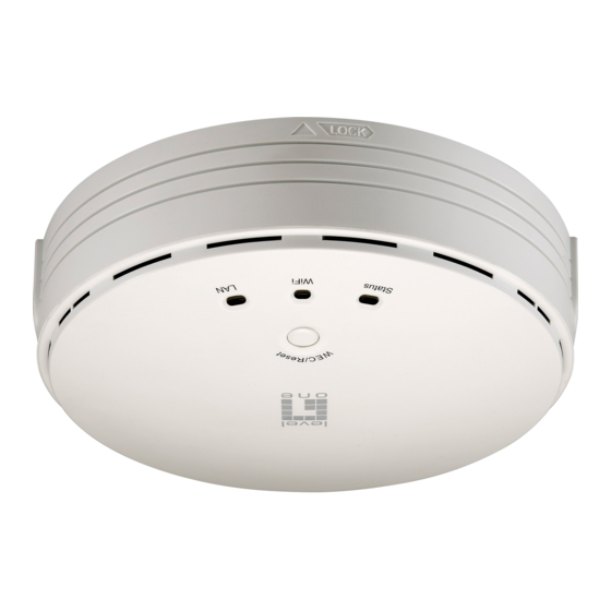
Page 10: Led Indicators
1.2.5 LED Indicators Description 1. When the device is booted up and ready: 2. When WEC/Reset is triggered (with button pressed): Status LED flashes at different rate according button-pressed duration. Stage 1 (1 ~ 5 sec) : Flash very fast Status Stage 2 (6 ~ 10 sec) : Flash twice per second Stage 3 (11~15 sec) : Flash once per second... -
Page 11: Button Definition
1.2.6 Button Definition There is one multi-function push button “WEC/Reset” in this device. According to different button pressed duration, the device will take specific reaction. For ease of interacting with the device, you can also check the Status and WiFi LED to determine when to release the button. - Page 12 Configuration (Press 3 sec) the easy configuration process also supports “Slave to Slave” configuration. (Slave to Slave) 1. Press the WEC/Reset button of the first Slave AP (say Slave1 that has been paired and configured) for 1~3 seconds, release it to trigger the WEC process.
- Page 13 Configuration (Press 13 seconds and release it. sec) 2. The Slave will marked un-configured device, so that it can be paired with another Master or configured Slave AP later. For Master AP, there is no effect on this button behavior. 1.
-
Page 14: Chapter 2 Getting Started
Chapter 2 Getting Started Before you can install this product to designated location and make it operate properly, you have to configure the device setting to fit in your network environment. Hardware Preparation: a. Connect an Ethernet cable between this device and the computer that you will operate to set up the device. -
Page 15: Easy Setup Via Web Ui
After applying this setting, you can now access to the web UI for configuring the device. Easy Setup via Web UI You can browse web UI to configure the device. Firstly you need to launch the Setup Wizard browser first and then the Setup Wizard will guide you step-by-step to finish the basic setup process. - Page 16 Select “Wizard” for basic settings in a simple way. Or, you can go to Basic Network / Advanced Network / Applications / System to setup the configuration by your own selection. Press “Next” to start the Setup Wizard.
- Page 17 Configure with the Setup Wizard Step 1 You can change the password of administrator here. Step 2 LAN IP Address. You have to change the IP address of this device according to your network configuration. Step 3-1 Wireless settings. You can specify the Wireless setting for VAP1.
-
Page 18: Use Wec Button To Setup Wireless Profiles
Step 4 Check the information again. Step 5 System is applying the setting. Step 6 Click finish to complete it. Use WEC Button to Setup Wireless Profiles WEC (Wireless Easy Connection) is an easy configuration feature that is similar to well-known WPS function. -
Page 19: One Master And Several Isolated Slaves
2.2.1 One Master and several isolated Slaves As illustrated in above figure, how to configure the three APs (AP1, AP2, AP3) to build up the “staff” wireless network? You can follow the procedure bellow: Step Button Description 1. Make sure AP1 is in Master Mode (WiFi LED should be “Green”... - Page 20 Master to Slave WEC: 1. Trigger AP1 into WEC configuration process via pressing the WEC button for 3 second. Easy configure AP2 via 2. Trigger AP2 into WEC configuration process via WEC. pressing the WEC button for 3 second. 3. It takes 30 ~ 60 seconds for the device to finish the WEC configuration process.
-
Page 21: One Master And A Series Of Connected Slaves
Ethernet cables to each repeater. As illustrated in above figure, if you intend to deploy 4 APs (AP1 ~ AP4) to create a “LevelOne” wireless network, you can follow the procedure below: Step Button Description 1. - Page 22 Master to Slave WEC: 1. Trigger AP1 into WEC configuration process via pressing the WEC button for 3 second. Easy configure AP2 via 2. Trigger AP2 into WEC configuration process via WEC. pressing the WEC button for 3 second. 3. It takes 30 ~ 60 seconds for the device to finish the WEC configuration process.
- Page 23 Besides, You can also check the AP4’s WiFi LED, it should be “Solid Amber” if AP4 already connected AP3. Although such wireless repeater function is available, there are limitations for such topology. First, the available bandwidth for AP2 ~ AP4 will be decayed due to it is connected to it peer AP wirelessly.
-
Page 24: Chapter 3 Making Configurations
Chapter 3 Making Configurations Whenever you want to configure your network or this device, you can access the Configuration Menu by opening the web-browser and typing in the IP Address of the device. The default IP Address is: 192.168.1.1. In the configuration section you may want to check the connection status of this device, to do Basic or Advanced Network setup or to check the system status. - Page 25 Afterwards, you can go Wizard, Basic Network, Advanced Network, Application or System respectively on left hand side of web page. Note: You can see the Connection Status screen below after you logged in. You can see all the status of this device in the ‘Status’ main menu section. Note :...
-
Page 26: Basic Network
Basic Network You can enter Basic Network for Ethernet LAN, Wireless and IPv6 settings in this web page. 3.1.1 Ethernet LAN 1. Device Network Type: This device supports two network types for connecting to your local network. -
Page 27: Wireless
Static IP: Allow a device to act as a Static host. If you need Static host and please entry IP Address. DHCP: Allow a device to act as a host requesting configuration parameters, such as an IP address from a DHCP server. Note: Please check if there is DHCP server in your Network, first. -
Page 28: Wireless Setup
The embedded RF Module1 is a IEEE 802.11b/g/n compliant 2.4GHz Wireless Module. 3.1.2.1 Wireless Setup There are several wireless operation modes provided by this device. They are: “AP Only Mode”, “WDS Hybrid Mode”, “WDS Only Mode”, and “Universal Repeater Mode”. You can choose the expected mode and configure the device manually. Besides manually configuration the devices to be deployed one by one, you can also configure your devices via the simple WEC configuration approach as stated in last Chapter. - Page 29 1. Wireless Module: Enable the wireless function. 2. Wireless Operation Mode: Choose “AP Only Mode” from the list. 3. Green AP: Enable the Green AP function to reduce the power consumption when there is no wireless traffic. AP Number: This device supports up to 8 SSIDs at the same time for you to manage your wireless networks.
- Page 30 VLAN ID: This device supports mapping of a SSID to a certain VLAN ID to separate workgroups across wireless and wired domains. By default, it is not enables. If you enabled this function, you have to specify a VLAN ID for the wireless network.
- Page 31 authentication process have the same "shared" key or passphrase. The shared key is manually set on both the client station and the AP. Three types of shared key authentication are available today for home or small office WLAN environments. Auto The gateway will select appropriate authentication method (Open or Shared) according to the WiFi client’s request automatically.
-
Page 32: Wds Hybrid Mode
64 hexadecimal (0, 1, 2…8, 9, A, B…F) digits, or 8 to 63 ASCII characters as the shared key. The key value is shared by the RADIUS server and this router. This key value must be consistent with the key value in the RADIUS server. Afterwards, click on “Save”... - Page 33 1. Lazy Mode: This device support the Lazy Mode to automatically learn the MAC address of WDS peers, you don’t have to input other peer AP's MAC address. However, not all the APs can be set to enable the Lazy mode simultaneously; at least there must be one AP with all the WDS peers’...
- Page 34 network. Therefore, if this setting is configured as “Disable”, you can hide the wireless network from been scanned by wireless clients. Those who know the SSID can manually specify the SSID on their client device to connect the hidden wireless network. 6.
-
Page 35: Wds Only Mode
Shared Shared key authentication relies on the fact that both stations taking part in the authentication process have the same "shared" key or passphrase. The shared key is manually set on both the client station and the AP. Three types of shared key authentication are available today for home or small office WLAN environments. - Page 36 1. Lazy Mode: This device support the Lazy Mode to automatically learn the MAC address of WDS peers, you don’t have to input other peer AP's MAC address. However, not all the APs can be set to enable the Lazy mode simultaneously; at least there must be one AP with all the WDS peers’...
- Page 37 Regulatory Domain. The factory default setting is auto channel selection. It’s recommended to choose a channel that is not used in your environment to reduce radio interference 4. Wireless Mode: The RF1 module supports 802.11b/g/n modes. You can also choose “N only”, “G/N mixed” or “B/G/N mixed”. The factory default setting is “B/G/N mixed”.
-
Page 38: Universal Repeater Mode
hexadecimal (0, 1, 2…8, 9, A, B…F) digits, or 8 to 63 ASCII characters as the pre-share key. WPA2-PSK Select Encryption mode and enter the Pre-share Key. You can fill in 64 hexadecimal (0, 1, 2…8, 9, A, B…F) digits, or 8 to 63 ASCII characters as the pre-share key. - Page 39 1. Green AP: Enable the Green AP function to reduce the power consumption when there is no wireless traffic. 2. Network ID (SSID): Network ID is used for identifying a Wireless LAN. Client stations can roam freely over this device and other Access Points that have the same Network ID.
-
Page 40: Advanced Wireless Setup
5. VLAN ID: This device supports mapping of a SSID to a certain VLAN ID to separate the workgroups across wireless and wired domains. By default, it is not enables. If you enabled this function, you have to specify a VLAN ID for the wireless network. - Page 41 1. Beacon interval: Beacons are packets sent by a wireless router to synchronize wireless devices. 2. Transmit Power: Normally the wireless transmission power operates at 100% out power specification of this device. You can lower down the power ratio to prevent transmissions from reaching beyond your corporate/home office or designated wireless area.
- Page 42 8. AP Isolation: If you enabled multiple VAPs in this device, you can further decide whether the wireless clients associated to different VAPs can access to each other or not. When you enabled the AP Isolation function, Each VAP is isolated to the others consequently.
-
Page 43: Ipv6
3.1.3 IPv6 The growth of the Internet has created a need for more addresses than are possible with IPv4. IPv6 (Internet Protocol version 6) is a version of the Internet Protocol (IP) intended to succeed IPv4, which is the protocol currently used to direct almost all Internet traffic. -
Page 44: Advanced Network
Advanced Network This device also supports other advanced network features for you to further manage the device. You can finish the configuration for Firewall, and Management in this section. 3.2.1 Firewall 3.2.1.1 MAC Address Control MAC Address Control allows you to assign different access right for different users and to assign a specific IP address to a certain MAC address. -
Page 45: Management
2. Association control: Check "Association control" to enable the control of which wireless client can associate to the wireless LAN. If a client is denied to associate to the wireless LAN, it means the client can't send or receive any data via this device. - Page 46 1. Enable SNMP: Enable this Function. 2. SNMP Version: Supports SNMP V1, V2c, and V3. 3. Get Community: The community of GetRequest that this device will respond. This is a text password mechanism that is used to weakly authenticate queries to agents of managed network devices.
- Page 47 accounts. You can specify the account permission as “Read” or “Read/Write” respectively. 6. User 1/2 AUTH Mode: Select MD5 or SHA as the method of password encryption for the specified level of access, or to disable authentication. 7. User 1/2 Privacy Mode: You can configure the SNMP privacy mode. There are three modes for you to choose: “noAuthNoPriv”...
-
Page 48: System
System In this section you can see system information, system logs, use system tools for system update and do service scheduling and system administration setting. 3.3.1 System Information You can view the System Information in this page. -
Page 49: System Status
3.3.2 System Status 3.3.2.1 Web Log Log Types: You can select the log types to be collected in the web log area. There are “System”, “Attacks”, “Drop”, and “Debug” types for you to select. Web Log: You can browse, refresh, download, and clear the log messages. 3.3.2.2 Syslog This device also can export system logs to specific destination by means of syslog (UDP) and SMTP(TCP). -
Page 50: Email Alert
3.3.2.3 Email Alert This device can also export system logs via sending emails to specific recipients. The items you have to setup include: Setting of Email alert: Check if you want to enable Email alert (send syslog via email). SMTP Server: Port: Input the SMTP server IP and port, which are connected with ':'. -
Page 51: Fw Upgrade
You can change the System Password here. We strongly recommend you to change the system password for security reason. Click on “Save” to store your settings or click “Undo” to give up the changes. 3.3.3.2 FW Upgrade If new firmware is available, you can upgrade device firmware through the WEB GUI here Press “browse”... -
Page 52: System Time
3.3.3.3 System Time If new firmware is available, you can upgrade device firmware through the WEB GUI here Time Zone: Select a time zone where this device locates. Auto-Synchronization: Check the “Enable” checkbox to enable this function. Besides, you can select a NTP time server to consult UTC time. Sync with Time Server: Click on the button if you want to set Date and Time by NTP Protocol. -
Page 53: Others
3.3.3.4 Others In this section you can do system backup, reset to default, system reboot settings and ping test. Backup Setting: You can backup your settings by clicking the “Backup” button and save it as a bin file. Once you want to restore these settings, please click Firmware Upgrade button and use the bin file you saved. -
Page 54: Mmi
3.3.4 MMI 3.3.4.1 Web UI You can set UI administration time-out duration in this page. If the value is “0”, means the time-out is unlimited. -
Page 55: Chaptor 4 Troubleshooting
CHAPTOR 4 Troubleshooting This Chapter provides solutions to problems for the installation and operation of the WiFi Concurrent 300Mbps Business AP. You can refer to the following if you are having problems. 1 Why can‟t I configure the device even the cable is plugged and the LED is lit? Do a Ping test to make sure that the WiFi Access Point is responding. - Page 56 installation steps listed below are applicable for all network adapters. Go to Start > Right click on “My Computer” > Properties. Select the Hardware Tab. Click Device Manager. Double-click on “Network Adapters”. Right-click on Wireless Card bus Adapter or your specific network adapter. Select Properties to ensure that all drivers are installed properly.
- Page 57 IV. Turn off the WiFi Concurrent 300Mbps Business AP and the client, then restart it and then turn on the client again. Ensure that the LEDs are indicating normally. If not, make sure that the power and Ethernet cables are firmly connected. VI.
- Page 58 interference. III. Keep your product away from electrical devices that generate RF noise, like microwaves, monitors, electric motors, etc. 4 What to do if I forgot my encryption key? 1. Go back to advanced setting to set up your Encryption key again. 2.
-
Page 59: Appendix A. Assigning A Static Ip In Windows Pc
Appendix A. Assigning a Static IP in Windows PC When organizing your local network it’s easier to assign each computer it’s own IP address than using DHCP. Here we will take a look at doing it in XP, Windows 7, Windows 8 and Windows 8.1. - Page 60 Then when the Network and Sharing Center opens, click on Change adapter settings. This will be the same on Windows 7 or 8.x. Right-click on your local adapter and select Properties.
- Page 61 In the Local Area Connection Properties window highlight Internet Protocol Version 4 (TCP/IPv4) then click the Properties button. Now select the radio button Use the following IP address and enter in the correct IP, Subnet mask, and Default gateway that corresponds with your network setup. Then enter your Preferred and Alternate DNS server addresses.
- Page 62 you entered. When you’re finished click OK. Now close out of the Local Area Connections Properties window. Windows 7 will run network diagnostics and verify the connection is good. Here we had no problems with it, but if you did, you could run the network troubleshooting wizard.
- Page 63 Now you can open the command prompt and do an ipconfig to see the network adapter settings have been successfully changed. Windows XP In this example we’re using XP SP3 Media Center Edition and changing the IP address of the Wireless adapter. To set a Static IP in XP right-click on My Network Places and select Properties.
- Page 64 Highlight Internet Protocol (TCP/IP) and click the Properties button. Now change the IP, Subnet mask, Default Gateway, and DNS Server Addresses. When you’re finished click OK.
- Page 65 You will need to close out of the Network Connection Properties screen before the changes go into effect. Again you can verify the settings by doing an ipconfig in the command prompt. In case you’re not sure how to do this, click on Start then Run.
- Page 66 In the Run box type in cmd and click OK. Then at the prompt type in ipconfig and hit Enter. This will show the IP address for the network adapter you changed. If you have a small office or home network, assigning each computer a specific IP address makes it a lot easier to manage and troubleshoot network connection problems.
-
Page 67: Appendix B. Licensing Information
Appendix B. Licensing information This product includes copyrighted third-party software licensed under the terms of the GNU General Public License. Please refer to the GNU General Public License below to check the detailed terms of this license. The following parts of this product are subject to the GNU GPL, and those software packages are copyright by their respective authors. - Page 68 GNU GENERAL PUBLIC LICENSE Version 2, June 1991 Copyright (C) 1989, 1991 Free Software Foundation, Inc. 59 Temple Place, Suite 330, Boston, MA 02111-1307 USA Everyone is permitted to copy and distribute verbatim copies of this license document, but changing it is not allowed. Preamble The licenses for most software are designed to take away your freedom to share and change it.
- Page 69 1. You may copy and distribute verbatim copies of the Program's source code as you receive it, in any medium, provided that you conspicuously and appropriately publish on each copy an appropriate copyright notice and disclaimer of warranty; keep intact all the notices that refer to this License and to the absence of any warranty;...
- Page 70 4. You may not copy, modify, sublicense, or distribute the Program except as expressly provided under this License. Any attempt otherwise to copy, modify, sublicense or distribute the Program is void, and will automatically terminate your rights under this License. However, parties who have received copies, or rights, from you under this License will not have their licenses terminated so long as such parties remain in full compliance.
- Page 71 11. BECAUSE THE PROGRAM IS LICENSED FREE OF CHARGE, THERE IS NO WARRANTY FOR THE PROGRAM, TO THE EXTENT PERMITTED BY APPLICABLE LAW. EXCEPT WHEN OTHERWISE STATED IN WRITING THE COPYRIGHT HOLDERS AND/OR OTHER PARTIES PROVIDE THE PROGRAM "AS IS" WITHOUT WARRANTY OF ANY KIND, EITHER EXPRESSED OR IMPLIED, INCLUDING, BUT NOT LIMITED TO, THE IMPLIED WARRANTIES OF MERCHANTABILITY AND FITNESS FOR A PARTICULAR PURPOSE.