Table of Contents
Advertisement
Quick Links
Networked PIP Series Reference Manual
TCP / IQ
Network Programmable Input Processors with HiQnet™, TCP/IQ™ ,
SmartAmp ™ Features, Load Supervision for Crown PIP2™ -Compatible
Amplifiers
Obtaining Other Language Versions: To obtain information in another language about
the use of this product, please contact your local Crown Distributor. If you need assistance
locating your local distributor, please contact Crown at 574-294-8000.
This manual does not include all of the details of design, production, or variations of the
equipment. Nor does it cover every possible situation which may arise during installation,
operation or maintenance. If special assistance is needed beyond the scope of this manual,
please contact the Crown Technical Support Group.
The information provided in this manual was deemed accurate as of the publication date.
However, updates to this information may have occurred. To obtain the latest version of this
manual, please visit the Crown website at www.crownaudio.com.
Trademark Notice: Crown, Crown Audio, Amcron, Com-Tech, Macro-Tech, IQ and IQ
System are registered trademarks of Crown International. TCP/IQ, SmartAmp, IQ2, PIP and
PIP2 are trademarks of Crown International. HiQnet is a trademark of Harman International
Industries, Inc. Other trademarks are the property of their respective owners.
Some models may be exported under the name Amcron.
©2008 by Crown Audio
U.S.A. Telephone: 574-294-8000
ANALOG AUDIO INPUTS
,
and CobraNet™ Connectivity (USP3/CN only)
®
Inc., 1718 W. Mishawaka Rd., Elkhart, Indiana 46517-9439
IN USE/
LINK/
CONDUCTOR
ACTIVITY
®
136763-6
4/08
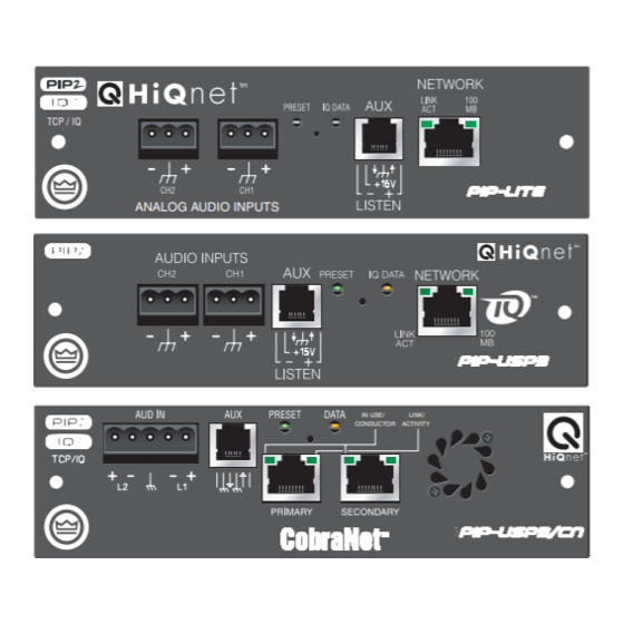
PIP-LITE
PIP-USP3
tm
PIP-USP3/CN
Advertisement
Table of Contents
Troubleshooting

Related Manuals for Crown PIP-LITE


Summary of Contents for Crown PIP-LITE
- Page 1 Amplifiers Obtaining Other Language Versions: To obtain information in another language about the use of this product, please contact your local Crown Distributor. If you need assistance locating your local distributor, please contact Crown at 574-294-8000. This manual does not include all of the details of design, production, or variations of the equipment.
-
Page 2: Fcc Compliance Notice
• Connect the equipment into an outlet on a circuit different from that to which the receiver is connected. • Consult the dealer or an experienced radio/TV technician for help. page 2 Crown Technical Support WARNING Networked PIP Series Reference Manual... -
Page 3: Declaration Of Conformity
United Kingdom Equipment Type: Control System Components Family Name: PIP Model Name: PIP-Lite, PIP-USP3, PIP-USP3/CN EMC Standards: EN 55103-1:1995 Electromagnetic Compatibility – Product Family Standard for Audio, Video, Audio- Visual and Entertainment Lighting Control Apparatus for Professional Use, Part 1: Emissions... -
Page 4: Quick Install Procedure
100 Megabit Ethernet Switch with a standard straight CAT5 network cable. (See Sec- tion 3.4 if more information is needed.) A 10 Megabit connection will work with the PIP-Lite and PIP-USP3 but is not recommended for systems with a high number of components. A 10 Megabit connection will not work with the PIP-USP3/CN. -
Page 5: Table Of Contents
5.1.2 Preset Indicator ... 26 5.1.3 Network Connector ... 26 5.1.4 Link/Activity Indicator ... 26 5.1.5 100 Mb Indicator (PIP-Lite, USP3 only) ... 26 5.1.6 CobraNet Connectors (USP3/CN only)... 26 5.1.7 CobraNet In-use/Conductor Indicator 5.1.8 Balanced Audio Inputs ... 27 5.1.9 Aux Input/Output Connector ... - Page 6 Table of Contents (continued) 5.2.5 Thermal Headroom Level Monitor ... 29 5.2.6 Power/Standby Control ... 29 5.2.7 Signal Mute ... 29 5.2.8 Polarity Inverter ... 30 5.2.9 Input Signal Fader ... 30 5.2.10 Dynamic Gain Monitors (Ghost Faders) ... 30 5.2.11 Amplifier Information ...
-
Page 7: Illustrations
7.1.1 AUX Output ...53 7.1.2 AUX Input ...54 7.1.3 Listen Bus Wiring ...55 8 Specifications ... 56 9 Using the PIP-Lite with the PIP-USP2 Adapter ... 58 10 Troubleshooting... 60 11 Service ... 62 11.1 International and Canada Service...62 11.2 US Service ...62 11.2.1 Factory Service ...62... - Page 8 5.4 Typical Impedance Test Plot of Full-Range Speaker ...40 5.5 Frequency Response of Amplifier and DSP in dBu...41 5.6 Impedance Plot and Frequency Response Plot...41 6.1 Input Wiring for the PIP-Lite and PIP-USP3 ...45 6.2 Input Wiring for the PIP-USP3/CN...45 6.3 A TCP/IP Network ...46 6.4 Multiple-Network Communications Via an IP Router ...48...
-
Page 9: Welcome
*A PIP2-compatible amplifier is necessary to use these PIP modules. To determine if the amplifier is PIP2 compatible, look for the with older Crown PIP amplifiers (except the PIP-Lite if a USP2 adapter is first installed in the amplifier. See Section 9 for more detail on the USP2 adapter.) Note that the PIP-Lite and PIP-USP3 cannot receive or transmit CobraNet audio. -
Page 10: Unpacking
Only the consignee may initiate a claim with the carrier for shipping damage. Crown will be happy to cooperate fully as needed. Save the shipping carton as evidence of damage for the shipper's inspection. -
Page 11: Controls, Indicators And Connectors
During operations of the switch, the Data indicator flashes as an aid to the user. See Section 4.1.11. D. Data Indicator Flashes when the PIP-Lite receives a valid command that is addressed to the PIP-Lite. See Section 4.1.1. E. AUX Connector AUX input, AUX output, and Listen Bus. -
Page 12: Pip-Usp3
Networked PIP Series 2.2 PIP-USP3 Please refer to Figure 2.3. A Balanced Audio Input Connector 3-pin removable barrier strip connector for each audio channel. B. AUX Connector AUX input, AUX output, and Listen Bus. C. Preset Indicator Signals the number of the current preset, if active, by flashing a series of flashes equal to the current preset number. -
Page 13: Pip-Usp3/Cn
Networked PIP Series 2.3 PIP-USP3/CN A. Preset Indicator Signals the number of the current preset, if active, by flashing a series of flashes equal to the current preset number. See Section 4.1.2. B. Reset/Preset Switch Used to change presets, restore settings to factory default or restore all the presets to the factory defaults. -
Page 14: Installation
The PIP comes ready to install in the amplifier. This unit does not require setting the “IQ address” as the older current loop, Crown bus, units did. Each PIP (as well as all network components) comes preprogrammed with a unique network (MAC) address. The IQ or HiQ- net address is then set (automatically or manually) via the IQwic or SystemArchitect control software. -
Page 15: Install The Pip Into The Amplifier
Networked PIP Series EXACT CONFIGURATION OF AMPLIFIER AND RIB- BON CABLES MAY VARY Figure 3.1 Installing the PIP into the Amplifier Reference Manual 3.3 Install the PIP Into the Amplifier Carefully ground yourself to the chassis of the amplifier before installing the PIP. It is a good idea to maintain ground contact between yourself and the amplifier while inserting the module into the amplifier. -
Page 16: Install The Wiring
Networked PIP Series 3.4 Install the Wiring IMPORTANT: Please read the wiring rules below before installing the wiring. If your com- puter does not communicate with the network devices after installation and addressing, re-read this section, as well as Section 4.2 on addressing rules. 3.4.1 Wiring Rules •... -
Page 17: Wiring Instructions
Networked PIP Series 3.4.2 Wiring Instructions 1. PIP-Lite and PIP-USP3 ONLY: Using a standard CAT5 cable, connect the network con- nector to a 100 Mb port on an Ethenet switch that is used to form the control network. For more detail see Section 6.2, Network Basics. If the PIP module is not to be connected to a control network, it can be temporaily connected to a computer’s Ethernet port with a crossover... - Page 18 2. Connect the Audio Input Wiring. The PIP module is equipped with removable barrier block connectors for each channel’s input. See Section 5.1 for more detail on audio wiring. The USP3/CN allows the use of standard balanced audio inputs to act either as CobraNet backup, an emergency override of CobraNet audio, or as an audio input to the CobraNet network.
-
Page 19: How To Set Up Tcp/Ip
Networked PIP Series 4 How to Set Up TCP/IP 4.1 Introduction Before you set up a TCP/IP network with addressing, it’s important to understand all the terms involved. The following glossary explains network terminology. 4.1.1 Glossary Network: A group of interconnected components, such as a central computer, network switching equipment, and other computers or devices. - Page 20 ID. There are many resources available on the Internet for IP and subnet calculation. For a stand-alone system, Crown has provided a worksheet of a tested configuration later in this section. DHCP (Dynamic Host Configuration Protocol): This a protocol for automatically assigning IP addresses to devices on a network.
-
Page 21: Tcp/Ip Addressing Rules
Networked PIP Series 4.2 TCP/IP Addressing Rules In the next section, you will be assigning static TCP/IP addresses to the devices in your network. When you do so, be sure to follow the addressing rules below. Otherwise, the computer may not communicate with the devices. 1. -
Page 22: Network Setup Wizard
Networked PIP Series 4.3 Network Setup Wizard The network setup wizard can assist you in setting up your network for the first time. Using the wizard, you can address your components and be informed of addressing and other errors in the system. Please note that this wizard is designed to work with devices that are on the same physical network segment as the computer it is running on. - Page 23 The wizard is able to avoid assigning IP addresses used by other Crown or Harman compo- nents, but it cannot detect if it has assigned an address that is currently being used by another computer or TCP/IP device on the network.
-
Page 24: Operation
USP3/CN if CobraNet audio is disrupted. Crown strongly recommends the use of a 100 Mb Ethernet network for control and monitor- ing. While some Crown products will function on a 10 Mb Ethernet network, their perfor- mance and network expansion capability will be limited. -
Page 25: Pip-Usp3 And Pip-Usp3/Cn Signal Flow Block
Networked PIP Series Figure 5.2 shows the system block diagram of the USP3 and USP3/CN. Figure 5.2 PIP-USP3 and PIP-USP3/CN Signal Flow Block Diagram Reference Manual page 25... -
Page 26: Hardware
CobraNet network data witin a few seconds. Connection is made using standard CAT5 cable to a network switch port. Crown strongly recommends the use of switches and not hubs in the implementation of the CobraNet network. Use of hubs will limit the amount of CobraNet traffic that can reside on the network and create unnecessary limitations in the network. -
Page 27: Cobranet In-Use/Conductor Indicator (Usp3/Cn Only)
This removable barrier block connector allows line level audio signals to be input to the PIP. The PIP-Lite and PIP-USP3 use two 3-pin connectors (one per channel), while the PIP-USP3/CN uses one 5-pin connector that handles both channels. The USP3/CN accepts line level analog audio signals in addition to the digital audio that is available through the CobraNet network. -
Page 28: Listen Bus Or Foldback
IQ software control. Multiple PIP-Lite and PIP-USP3 modules can have their Listen Bus outputs wired onto a single bus allowing the system operator to listen to any of their outputs. -
Page 29: Features Of All Three Modules
Networked PIP Series 5.2 Features of All Three Modules The exact location of the following controls varies with the software. These features might be inaccessible from the standard control panel, but accessible from a custom control page. 5.2.1 User Presets The control settings for all the functions can be stored as presets. -
Page 30: Polarity Inverter
Networked PIP Series 5.2.8 Polarity Inverter The input signal polarity of each channel can be independently inverted. 5.2.9 Input Signal Fader Each input signal can be adjusted under software control. The gain range is +20dB to –80dB in 0.5dB steps. In addition to adjustment of the post input router signal, each Analog Audio Input has a separate Fader that allows the trim of the Analog Audio Input before the Input Router. -
Page 31: Auto Standby
Networked PIP Series The software offer many options to further report errors, including audible alerts, printout, email, pager, serial port and fax. The exact options vary depending if you are using System Architect or IQwic. The options are set in the software. The following describes each error source. -
Page 32: Input Signal Compressor/Limiter
Networked PIP Series 5.2.18 Input Signal Compressor/Limiter An input signal compressor/limiter is available for each channel. Five parameters control this feature: Enable: Enables or disables this function. Threshold: Sets the level, in dBu, above which the compressor begins to attenuate the input signal. -
Page 33: Average Power Limiter
Networked PIP Series Release Time: Sets the release time of the compressor. The release time is defined as the time it takes the limiter to increase the output signal by 20 dB. The range is from 10 milli- seconds to 10 seconds. 5.2.20 Average Power Limiter This limits the long-term output power of the amplifier. -
Page 34: Load Supervision
Networked PIP Series 5.2.24 Load Supervision The load supervision feature allows real-time monitoring of the load connected to each amplifier channel. When enabled, the PIP continuously monitors the amplifier output voltage and current, and calculates the long-term average load impedance. The measured load impedance is compared against the user-defined high and low limits. -
Page 35: Typical Load Characteristics
Networked PIP Series Most amplifier/load systems can be configured and supervised by following these steps: 1. Configure your audio system using a known “good” load, then enable the Load Supervi- sion feature. 2. Provide typical program material at a level high enough to light the “test” indicator. 3. -
Page 36: Pip-Usp3 And Pip-Usp3/Cn Features
Networked PIP Series These anomalies are easily averaged out by the PIP supervision algorithm in most systems. However, there may be some extreme situations for very narrow bandwidth (i.e. single-note) signals and/or very widely varying loads that the algorithm simply cannot overcome. In these cases, widening the high and low limits will help decrease the “sensitivity”... -
Page 37: Noise Generator
5.3.6 SLM (System and Load Monitoring) Tab of the Control Panel This function is available only in IQwic, not in System Architect v1.0. Also, it is available for the PIP-USP3 and PIP-USP3/CN, but not for the PIP-Lite. Figure 5.3 SLM Tab of the Control Panel... - Page 38 The SLM tab allows you to test network-PIP components for impedance vs. frequency and frequency response. The USP3 and USP3/CN include a signal generator to provide a swept sine-wave signal for the tests. Described below are the three sections of the SLM tab: Sweep, Channel SLM and Tolerance.
- Page 39 Networked PIP Series • Reference measures both the impedance-vs.-frequency and frequency response of a known good component. All other tests are compared to these results until a new reference is created. Impedance and Frequency Pass/Fail Indicators These show whether the channel passed or failed the selected test. Start/Stop Frequencies These are the lowest and highest frequencies of the displayed curve.
-
Page 40: Typical Impedance Test Plot Of Full-Range Speaker
Networked PIP Series Curves Clicking on the "Curves" button will allow you to look at any of the curves that were gener- ated as the result of tests performed. These curves are displayed in a separate Curve Viewer. Some typical curves are shown in Figures 5.4, 5.5 and 5.6. In Figure 5.4, find the File Menu at the top left of the impedance plot. -
Page 41: Frequency Response Of Amplifier And Dsp In Dbu
Networked PIP Series Figure 5.5 Frequency Response of Amplifier and DSP in dBu Figure 5.6 Impedance Plot and Frequency Response Plot Reference Manual page 41... -
Page 42: Pip-Usp3/Cn Features
Networked PIP Series 5.4 PIP-USP3/CN Features 5.4.1 Input Signal Router Each channel of the PIP’s signal processing has an Input Signal Router that allows the choice of audio signal that will be used by the channel. The user may choose one of the fol- lowing configurations: •... -
Page 43: Cobranet Input Routing
Networked PIP Series System Name This parameter is user-settable to any alpha-numeric string of 30 characters or less. The intended use is to communicate a unique name for the particular device to a network. The System Name object is stored in presets. System Description This parameter is configured at the factory and is read-only. -
Page 44: Cobranet Output Routing
Networked PIP Series CobraNet Receive Channels Each CobraNet Bundle contains up to eight digital audio channels. Each channel is selected at its respective transmitter to contain none, 16-, 20- or 24-bit audio sample data. A total of two audio channels can be processed by the PIP-USP3/CN at any one time. Any of the eight channels on a bundle can be can be routed to either of the two processing channel inputs on the PIP-USP3/CN. -
Page 45: Audio Signal Wiring And Network Basics
• Turn the entire sound system off before changing any connections. Turn the level con- trols down before powering the system back up. Crown is not liable for damage incurred when any transducer or component is overdriven. -
Page 46: Network Basics
Networked PIP Series 6.2 Network Basics HiQnet and TCP/IQ are network based protocols that have the ability to control and monitor networked components over a common TCP/IP network. For components that have Cobra- Net capability, HiQnet and TCP/IQ have the ability to control and monitor these compo- nents over the same Ethernet network used for CobraNet audio, resulting in a single Category-5 connection for control, monitoring, and digital audio. - Page 47 Networked PIP Series Some of the features of HiQnet and TCP/IQ include: • Ability to quickly discover all components connected to the network. • Synchronization of multiple control points on a network. • Components on different Local Area Networks (LANs) through the use of an IP router. •...
-
Page 48: Multiple-Network Communications Via An Ip Router
Networked PIP Series AUDIO NETWORK VENUE NETWORK Computer PIP-Lite Computer PIP-USP3 Laptop PIP-USP3/CN 100Mb Switch IP Router 100Mb Switch Laptop Wireless Access Point Figure 6.4 Multiple-Network Communication Via an IP Router This allows the network designer to isolate network traffic from each other. For example, when using wireless devices to control IQ components, the bandwidth limitation of wireless devices will not allow them to reside on the same network with CobraNet. -
Page 49: A Closer Look At Cobranet (Pip-Usp3/Cn Only)
Networked PIP Series IP address of a known component on the component network as the Discovery Proxy within IQWin or TCPIQ Util. In System Architect it is done in Tools > Options > Network Settings > Manage Network Connections. 6.3 A Closer Look at CobraNet (PIP-USP3/CN only) Licensed by Peak Audio, CobraNet is a protocol, firmware and hardware that lets you transmit digital audio over a 100Base-T Fast-Ethernet network. -
Page 50: Audio Specs
Networked PIP Series Figure 6.6 Multi-Star Topology In larger Fast Ethernet networks, additional hubs, concentrators, and other network hardware are used to form a larger network, as shown in Figure 6.6. Today, commonly available networking cards are 10/100Base-T capable, which allows them to be used on either 10BaseT or 100Base-T networks. -
Page 51: The Conductor
Networked PIP Series The usual assignment is 8 channels at 20 bits. You can use fewer channels per bundle, but maximum size bundles are suggested for the most efficient use of network bandwidth. If 24- bit data is desired, then only 7 audio channels can be loaded into a single Bundle. In IQwic, you create audio connections between sending devices (transmitters) and receiv- ing devices (receivers). -
Page 52: Switched Networks
Networked PIP Series 6.3.6 Switched Networks A more complex CobraNet network can be built using Ethernet switches. Switches do not simply broadcast each and every packet to all nodes. Instead, they check each incoming data packet to determine its destination and (very quickly) transmit the data to only that des- tination port. -
Page 53: Advanced Features And Options
The AUX connector offers a means to tap some of the flexibility of the Harman Pro System Architect or Crown IQ System. It can be used to enable peripherals, send a signal to another system component, and send a line-level audio signal of the amplifier's output. -
Page 54: Aux Input
This input can be a temperature sensor, door closure switch, or operator pushbut- ton. It can be used by the IQ software to change configuration settings on any or all system devices. See the Harman Pro System Architect or Crown IQ System Help files for exact information. -
Page 55: Listen Bus Wiring
Networked PIP Series between 4 and 15 VDC. Externally supplied voltages should be referenced to AUX ground on pin 3. The AUX input features seven enhanced modes. The first six modes allow the AUX input to mute or power-down either or both channels. The AUX Input Inversion Control allows either a high or low AUX input to activate these functions. -
Page 56: Specifications
PIP. A green PRESET indicator flashes to indicate the selected and active user preset. PIP-Lite and PIP-USP3: A yellow LINK ACT indicator (integrated in the network connector) indicates a valid Ethernet link when lit and the presence of Ethernet traffic when flashing. A green 100 MB indicator (integrated in the network connector) indicates a valid 100 Megabit connection. - Page 57 Signal to Noise Ratio (USP3, USP3/CN only): 70 dB typical (A-weighted, 20Hz to 20kHz). Dynamic Range: PIP-Lite: >110 dB (A-weighted, 20 Hz to 20 kHz) PIP-USP3: >105 dB (A-weighted, 20Hz to 20kHz) PIP-USP3/CN: >105 dB (A-weighted, 20Hz to 20 kHz) Crosstalk (USP3, USP3/CN only): >...
-
Page 58: Using The Pip-Lite With The Pip-Usp2 Adapter
Macro-Tech 00 Series, Com-Tech 00 Series, and Studio Reference Series amplifiers) to access the power and versatility of the Crown PIP-Lite module. The PIP-USP3 and PIP- USP3/CN do not work with the IQ-PIP-USP2 Adapter. The IQ-PIP-USP2 Adapter can be installed into the following Crown amplifier models:... -
Page 59: Adapter
Networked PIP Series Please note the following differences when using the PIP-Lite with the IQ-PIP-USP2 Adapter: Different Identification within the software • The software recognizes and identifies the IQ-PIP-USP2 Adapter itself, rather than the host amplifier module (see Figure 9.1). -
Page 60: Troubleshooting
• Network configuration cable is disconnected or broken. To assist with troubleshooting, an option that forces the data indicator to remain lit is available through the software. Some Crown amplifiers also have a data indicator on their front panels. In these cases this indi- cator will light simultaneously with the PIP's data indicator. -
Page 61: Troubleshooting
Networked PIP Series 10 Troubleshooting Reference Manual IQ-PIP-LITE AND IQ-PIP-USP3 ONLY Problem: Yellow LINK ACT indicator in network connector does not illuminate or flash. Possible cause: Ethernet link is broken. IQ-PIP-LITE AND IQ-PIP-USP3 ONLY Problem: Yellow LINK ACT indicator is on but green 100 MB indicator in network connector does not illuminate. -
Page 62: Service
Service must be done at the Crown factory. Contact your local distributor for more information. 11.2 US Service Service must be done at the Crown factory (see Sections 9.2.1 and 9.2.2). It is important that you have your copy of the bill of sale as your proof of purchase. -
Page 63: Packing Instructions
11.2.4 Estimate Approval Approval of estimate must be given within 30 days after being notified by Crown Audio Inc. Units still in the possession of Crown after 30 days of the estimate will become the property of Crown Audio Inc. -
Page 64: Warranty
Crown International, 1718 West Mishawaka Road, Elkhart, Indiana 46517-4095 U.S.A. warrants to you, the ORIGINAL PURCHASER and ANY SUBSEQUENT OWNER of each NEW Crown product, for a period of three (3) years from the date of purchase by the original purchaser (the “warranty period”) that the new Crown product is free of defects in materials and workmanship. - Page 65 ITEMS EXCLUDED FROM THIS CROWNWARRANTY This Crown Warranty is in effect only for failure of a new Crown product which occurred within the Warranty Period. It does not cover any product which has been damaged because of any intentional misuse, accident, negligence, or loss which is covered under any of your insurance contracts.
- Page 66 Networked PIP Series THIS PAGE INTENTIONALLY LEFT BLANK Reference Manual page 66...
-
Page 67: Factory Service Information Form
Networked PIP Series Crown Factory Service Information Shipping Address: Crown Factory Service, 1718 W. Mishawaka Rd., Elkhart, IN 46517 SRA #: __________________(If sending product to Crown factory service.) Serial Number: _____________________ Individual or Business Name: _____________________________________________________________________ Phone #: _____________________________________ E-Mail: _______________________________________ Street Address (please, no P.O.