Table of Contents
Advertisement
Quick Links
CATEYE
URBAN WIRELESS
CYCLOCOMPUTER
CC-VT240W
•
This instruction manual is subject to change
without notice. See our website for the latest
instruction manual (PDF).
•
Please visit our website, where a detailed
Quick Start manual containing videos can be
downloaded.
http://www.cateye.com/products/detail/CC-VT240W/manual/
Setting up the
measurement
Changing settings
Warning/Caution
Product Warranty, etc.
1
Mounting the
computer
computer
Starting
1
2
3
4
SET
Advertisement
Table of Contents

Summary of Contents for Cateye Urban Wireless CC-VT240W
- Page 1 Mounting the computer CATEYE URBAN WIRELESS CYCLOCOMPUTER Setting up the CC-VT240W computer Starting measurement Changing settings • This instruction manual is subject to change without notice. See our website for the latest instruction manual (PDF). • Please visit our website, where a detailed Quick Start manual containing videos can be downloaded. Warning/Caution http://www.cateye.com/products/detail/CC-VT240W/manual/ Product Warranty, etc.
-
Page 2: Mounting The Computer
Mounting the computer Bracket band Bracket rubber pad Speed sensor Magnet Sensor rubber pad Nylon tie Bracket Dial (x2) Mount the bracket • When mounting on stem Bracket band Bracket rubber pad Stem Bracket • When mounting on handlebar Bracket band Bracket rubber pad Handlebar Bracket Correct When mounting the bracket on a handle- Wrong bar, adjust the angle of the bracket so that the back of the computer faces the speed sensor when the computer is attached. - Page 3 Mounting the computer Mount the speed sensor • Mount the speed sensor in a posi- Mounting on right front fork tion where the distance from the computer to the speed sensor is within the signal range. • Mounting on left front fork Nylon tie Speed sensor Pull tight Sensor rubber pad Mount the magnet Magnet To sensor zone Spoke...
-
Page 4: Test Operation
Mounting the computer Adjust the speed sensor and the magnet The magnet passes through The clearance between the the speed sensor zone. speed sensor and the magnet is within 5 mm (3/16”). Magnet Speed Sensor zone sensor Magnet Speed sensor (3/16”) * The magnet may be mounted at any position on spoke as long as attachment conditions are satisfied. -
Page 5: Setting Up The Computer
Setting up the computer When using the computer for the first time or resetting it to its factory default settings, clear all computer data following the procedure below. Battery case Short press cover MODE MENU Long press (2 sec.) MODE MODE Clear all data. Press the AC button on the back of the computer. -
Page 6: Set The Clock
Setting up the computer Set the clock. Time display mode (24h or 12h) Switch item Each time the MODE button is pressed and or increase held, settings switch from time display mode, numbers MODE to hours, to minutes. Switch screen * When 12h is selected, A (AM) or P (PM) is or move to next digit displayed at the top of the screen. MODE (Press and hold) Hours Minutes Press MENU to complete setup. Setup is completed and the computer switches MENU Setup complete to the measurement screen. For instructions on how to start measurement, refer to “Starting measurement” (page 8). - Page 7 Setting up the computer Tire circumference Tire circumference can be determined by either of the following two methods: • Measure the actual tire circumference (L) After ensuring that the tire pressure is appropriate, sit on your bike, roll it forward so that the tire makes one full revolution (use the valve or other marking as a reference), and measure the dis- tance traveled on the road. L cm • Tire size chart * The tire size or ETRTO code is indicated on the side of the tire. ETRTO Tire size L (cm) ETRTO Tire size L (cm) 28-590 26x1-1/8 40-254 14x1.50 37-590 26x1-3/8 47-254 14x1.75 40-305 16x1.50 37-584 26x1-1/2 47-305 16x1.75 650C Tubular 26x7/8...
-
Page 8: Starting Measurement
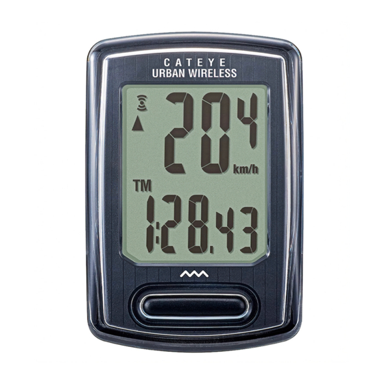
Starting measurement [Measurement screen] Sensor signal icon Flashes in sync with a sensor signal. Current speed Pace arrow 0.0 (4.0) – 105.9 km/h Indicates whether the current [0.0 (3.0) – 65.9 mph] speed is faster ( ) or slower ( ) Measurement unit than the average speed. Current function Switching current function Pressing MODE switches the current function displayed at the bottom of the screen. MODE MODE Elapsed Time Trip Distance Average Speed (*1) 0:00’00” – 9:59’59” 0.00 – 999.99 km [mile] 0.0 – 105.9 km/h [0.0 – 65.9 mph] MODE MODE... -
Page 9: Starting/Stopping Measurement
Starting measurement [Measurement screen] Starting/stopping measurement Measurement starts automatically when the bicycle moves. Measurement Measurement During measurement the measurement unit starts stops (km/h or mph) flashes. Resetting data Pressing and holding the MODE button when on the measurement MODE screen resets all measurement data to 0 (excluding Odo). (Press and hold) Power-saving function If the computer does not receive Measurement Power-saving any signal for 10 minutes, the screen screen power-saving screen is activated 10 minutes and only the clock is displayed. If MODE is pressed or a sensor signal is received while the pow- ersaving screen is activated, the 1 hour computer returns to the measure- Sleep ment screen. * If the computer is left on the power-saving screen for 1 hour, MODE SLEEP is displayed. When the computer is in this state, you can... -
Page 10: Changing Settings
Changing settings [Menu screen] On the measurement screen, press MENU to go to the menu screen. Various settings can be changed on the menu screen. * After changing settings, always press MENU to confirm changes. * When the menu screen is left on for 1 minute, the computer returns to the measurement screen. Measurement Menu screen Description screen Tire size selection You can use the simple setting method (select the size in inches) or the advanced setting method (enter the tire circumference) to set the tire size. MENU Change setting Simple setting MODE (Press and hold) Inch 24" 700c MODE MODE 22" 27" 20" MODE Confirm Switch size 27.5" 18" 29" MENU 16"... - Page 11 Changing settings [Menu screen] Measurement Menu screen Description screen Clock Lets you set the clock. * When 12h is selected, A (AM) or P (PM) is MODE MENU displayed at the top of the screen. Change setting Select display 12h ↔ 24h MODE (Press and hold) MODE MODE (Press and hold) MODE Set “hours” Increase numbers MODE Confirm MODE (Press MODE and hold) (Press and hold) MENU Set “minutes” Increase numbers MODE...
-
Page 12: Select Measurement Unit
Changing settings [Menu screen] Measurement Menu screen Description screen MENU MODE MODE MENU MODE MODE Select measurement unit Lets you select the measurement unit (km/h or mph). Change setting km/h↔mph MODE (Press and hold) MODE Confirm MENU... -
Page 13: Warning / Caution
Do not disassemble the computer. • Do not drop the computer. Doing so may result in malfunction or damage. • Always tighten the bracket band dial by hand. Using a tool or other object to tighten the dial may crush the screw thread. • When cleaning the computer and accessories, do not use thinners, benzine, or alcohol. • Risk of explosion if battery is replaced by an incorrect type. Dispose of used batteries according to local regulations. • The LCD screen may be distorted when viewed through polarized sunglass lenses. Wireless Sensor The speed sensor is designed with a maximum signal range of 70 cm (27”), to reduce the chance of interference. (The signal range is intended to serve as a rough guide only.) When handling the wireless sensor, note the following: • Signals cannot be received if the distance between the speed sensor and the computer is too large. • Signal range may be shortened due to low temperature and flat batteries. • Signals can be received only when the back of the computer is facing the speed sensor. Interference may occur, resulting in malfunction, if the computer is: • Near a TV, PC, radio, or motor, or in a car or train. • Close to a railroad crossing, railway tracks, TV transmitter station, or radar station. • Used with other wireless devices or certain battery-powered lights. This device complies with Part 15 of the FCC Rules. Operation is subject to the following two condi- tions:(1)This device may not cause harmful interference, and (2) this device must accept any interfer- ence received, including interference that may cause undesired operation. Modifications The FCC requires the user to be notified that any changes or modifications made to this device that are not expressly approved by CatEye Co., Ltd. May void the user ’s authority to operate the equipment. Hereby, CATEYE Co., Ltd., declares that this CC-VT240W is in compliance with the essential requirements and other relevant provisions of Directive 1999/5/EC. -
Page 14: Maintenance
Appendix Maintenance If the computer or accessories become dirty, clean with a soft cloth which is moistened with mild soap. Replacing the battery • Computer When the display becomes dim, replace the battery. Close Insert a new lithium battery (CR2032) with the (+) side up. * After replacing the battery, always follow the procedure CR2032 Open described in “Setting up the computer” (page 5). * If you make a note of the total distance value before replac- ing the battery, you will be able to continue from the same total distance by entering it after replacing the battery. • Speed sensor When the speed is not displayed even after adjusting cor- rectly, it is time to replace the battery. CR2032 Insert a new lithium battery (CR2032) with the (+) side up and close the battery cover firmly. * After replacing the battery, adjust the position of the Close magnet relative to the speed sensor as described in “Mounting the computer” (page 4) step 4. Open Troubleshooting The sensor signal reception icon does not flash. (Speed is not displayed.) •... -
Page 15: Main Specifications
1699691N 1665150 1602196 Please register your CatEye product on the website. Wheel magnet Lithium Speed sensor http://www.cateye.com/en/support/regist/ battery (SPD-01) Optional accessories 2-8-25, Kuwazu, Higashi Sumiyoshi-ku, Osaka 546-0041 Japan Attn: CATEYE Customer Service Phone : (06)6719-6863 Fax : (06)6719-6033 E-mail : support@cateye.co.jp URL : http://www.cateye.com [For US Customers] 1604100 1602980 1603891 CATEYE AMERICA, INC. 2825 Wilderness Place Suite 1200, Boulder CO 80301-5494 USA Out-front Nylon tie Speed sensor Phone : 303.443.4595 Toll Free : 800.5.CATEYE bracket bracket (SPD-02) Fax : 303.473.0006...