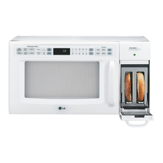
LG LTRM1240SW Service Manual
Hide thumbs
Also See for LTRM1240SW:
- Owner's manual & cooking manual (29 pages) ,
- Owner's manual (28 pages)
Table of Contents
Troubleshooting

Related Manuals for LG LTRM1240SW


Summary of Contents for LG LTRM1240SW
- Page 1 Website http://us.lgservice.com MICROWAVE OVEN SERVICE MANUAL MODEL: LTRM1240SW LTRM1240SB LTRM1240ST CAUTION BEFORE SERVICING THE UNIT, READ THE SAFETY PRECAUTIONS IN THIS MANUAL. July, 2004 P/NO : 3828W5S6018 Printed in Korea...
-
Page 2: Safety Precautions
SAFETY PRECAUTIONS This device is to be serviced only by properly qualified service personnel. Consult the service manual for proper service procedures to assure continued safety operation and for precautions to be taken to avoid possible exposure to excessive microwave energy. PRECAUTIONS TO BE OBSERVED BEFORE AND DURING SERVICING TO AVOID POSSIBLE EXPOSURE TO EXCESSIVE MICROWAVE ENERGY... -
Page 3: Table Of Contents
FOREWORD Read this Manual carefully. Failure to adhere to or observe the information in this Manual may result in exposing yourself to the Microwave Energy normally contained within the oven cavity. MECHANICAL SERVICE INFORMATION TABLE OF CONTENTS 1. Safety precautions ............................Inside front cover 2. -
Page 4: Specifications
SPECIFICATIONS ITEM DESCRIPTION LTRM1240SW MODEL LTRM1240SB LTRM1240ST Power Requirement 120 Volts AC 60 Hz Single phase, 3 wire grounded Microwave 1650W Toast 800W Power Output 1200 Watts full microwave power (IEC60705) Microwave Frequency 2450 MHz 2M214 Magnetron 0 ~ 90 min. -
Page 5: Cautions
CAUTIONS Unlike other appliances, the microwave oven is MICROWAVE RADIATION high-voltage and high-current equipment. Personnel should not be exposed to the microwave Though it is free from danger in ordinary use, energy which may radiate from the magnetron or extreme care should be taken during repair. other microwave generating device if it is improperly used or connection. -
Page 6: Installations
INSTALLATIONS BEFORE YOU BEGIN, READ THE FOLLOWING INSTRUCTIONS COMPLETELY AND CAREFULLY. INSTALLING GROUNDING INSTRUCTIONS 1. Empty the microwave oven and clean inside it with a For personal safety, this appliance must be fully grounded soft, damp cloth. Check for damage such as misaligned at all times. -
Page 7: Overall Circuit Diagram
6. OVERALL CIRCUIT DIAGRAM A. SCHEMATIC DIAGRAM... - Page 8 B. MATRIX CIRCUIT FOR TOUCH KEY BOARD...
-
Page 9: Operating Procedures
7. OPERATING PROCEDURES A. OVEN CONTROL PANEL MICROWAVE CONTROL AREA 1. DISPLAY. The Display includes a clock and indicators that tell you time of day, cooking time settings, and cooking functions selected. 2. STOP/CLEAR. Touch this pad to stop the oven or clear entries. 3. - Page 10 B. EASY USE TABLE TOASTER MICROWAVE OVEN (1) TOAST 1. Touch STOP/CLEAR. (1) KITCHEN TIMER 2. Touch TOAST. 1. Touch STOP/CLEAR. 3. Touch Darkness Control (1~9 step) 2. Touch KITCHEN TIMER. 4. Touch START. 3. Touch correct number for time. 4.
-
Page 11: Procedure For Measuring Microwave Energy Leakage
8. PROCEDURE FOR MEASURING MICROWAVE ENERGY LEAKAGE A. CAUTIONS B. MEASURING MICROWAVE ENERGY LEAKAGE (1) Be sure to check a microwave emission prior to servicing (1) Pour 275±15cc of 20±5 °C water in a beaker which is the oven if the oven is operative prior to servicing. graduated to 600 cc, and place the beaker in the center (2) The service personnel should inform the manufacturer, of the oven. - Page 12 D. MEASUREMENT WITH A FULLY ASSEMBLED OVEN G. POWER OUTPUT MEASUREMENT (1) After all components, including the outer panels, are (1) Fill the test beaker with 59 °F(15 °C) ~ 75 °F(24 °C) 1 liter tap fully assembled, measure for microwave energy water.
-
Page 13: Disassembly Instructions
9. DISASSEMBLY INSTRUCTIONS IMPORTANT NOTES: UNIT MUST BE DISCONNECTED FROM ELECTRICAL Remove screw OUTLET WHEN MAKING REPAIRS, RE-PLACEMENTS, ADJUSTMENTS AND CONTINUITY CHECKS. WAIT AT LEAST ONE MINUTE, UNTIL THE HIGH VOLTAGE securing CAPACITOR IN THE HIGH VOLTAGE POWER screw SUPPLY HAS FULLY DISCHARGED. THE CAPACITOR SHOULD BE DISCHARGED BY USING INSULATED WIRE - I.E. - Page 14 C. DOOR GROSS ASSEMBLY REMOVAL (1) Open the door. (2) Remove the choke cover cap very carefully with a flat-blade screwdriver. CAUTION : Be careful not to damage door seal plate by screwdriver. (3) Lift up and push the door. NOTE: 1.
- Page 15 D. MAGNETRON REMOVAL E. REMOVING THE TURNTABLE MOTOR (Figure 10) (Figure 11) 1) Disconnect the wire lead from the magnetron. 1) Remove the turntable and rotating ring. 2) Carefully remove the mounting screws holding the 2) Lay the unit down on its back. magnetron and the waveguide.
- Page 16 F. HIGH VOLTAGE TRANSFORMER REMOVAL I. INTERLOCK SYSTEM 1) Discharge the high voltage capacitor. 1) INTERLOCK MECHANISM 2) Disconnect the leadwire from magnetron, high voltage The door lock mechanism is a device which has been transformer, and capacitor. specially designed to eliminate completely microwave 3) Remove the screw holding the high voltage transformer to activity when the door is opened during cooking and thus the baseplate.
-
Page 17: Interlock Continuity Test
10. INTERLOCK CONTINUITY TEST WARNING : FOR CONTINUED PROTECTION AGAINST EXCESSIVE RADIATION EMISSION, REPLACE ONLY WITH IDENTICAL REPLACEMENT PARTS. TYPE NO. SZM-V 16-FA-63 OR VP-533A-OF FOR PRIMARY SWITCH TYPE NO. SZM-V 16-FA-62 OR VP-532A-OF FOR MONITOR SWITCH TYPE NO. SZM-V 16-FA-63 OR VP-533A-OF FOR SECONDARY SWITCH A. -
Page 18: Test And Checkout Procedures,And Troubleshooting
11. TEST AND CHECKOUT PROCEDURES, AND TROUBLESHOOTING CAUTIONS 1. DISCONNECT THE POWER SUPPLY CORD FROM THE OUTLET WHENEVER REMOVING THE OUTER CASE FROM THE UNIT. PROCEED WITH THE TEST ONLY AFTER DISCHARGING THE HIGH VOLTAGE CAPACITOR AND REMOVING THE WIRE LEADS FROM THE PRIMARY WINDING OF THE HIGH VOLTAGE TRANSFORMER. - Page 19 COMPONENTS TEST PROCEDURE RESULTS Antenna Gasket Chassis Filament NOTE: When testing the magnetron, be sure to install the magnetron gasket in the correct position and be sure that the gasket is in good condition. HIGH VOLTAGE 1. Check DC 9V battery before performing Normal: Approximately 9V CAPACITOR tests.
- Page 20 COMPONENTS TEST PROCEDURE RESULTS H.V.Diode (rectifer) STEP 1. Test the diode to see if it is shorted. Procedure: 1. Select the Ω scale on the meter. 2. Place the meter leads across the diode as pictured in Figure 14-a. The reading should be “40MΩ,”...
- Page 21 COMPONENTS TEST PROCEDURE RESULTS RELAY 2 1. Measure continuity. POWER (Power Relay) 2. Remove the lead wires and operate oven LEVEL at power level 1 through power level 10. 4 sec 18 sec 6 sec 16 sec 8 sec 14 sec 10 sec 12 sec 12 sec...
-
Page 22: Checkout Procedures
B. CHECKOUT PROCEDURES (1) CHECKOUT PROCEDURES FOR FUSE BLOWING CAUTION: REPLACE BLOWN FUSE WITH 15 AMPERE FUSE. PROBLEMS CAUSES Fuse blows immediately after Improper operation of the primary interlock, the door is closed. secondary interlock switches and/or the interlock monitor switch. Fuse blows immediately after the door is opened. - Page 23 (2) CHECKOUT PROCEDURES FOR RELAY. Microwave Oven Toaster - PROBLEM (A) - - PROBLEM (A) - FAN motor and oven lamp turn on without touching FAN motor and indicator light turn on without touching START key when the door is closed. START key when the door is closed.
- Page 24 (3) CHECKOUT PROCEDURES FOR CIRCUIT BOARD The following symptoms indicate a defective circuit board. (1) The start function fails to operate but the high (4) Some segments of one or more digits do not light up, or voltage Systems, the interlock switches, the door they continue to light up, or segments light when they sensing and the relay check good.
-
Page 25: Troubleshooting
C. TROUBLE SHOOTING WHEN YOU GET A COMPLAINT FROM YOUR CUSTOMER, EVALUATE THE COMPLAINT CAREFULLY. IF THE FOLLOWING SYMPTOMS APPLY, PLEASE INSTRUCT THE CUSTOMER IN THE PROPER USE OF THE TOASTER AND MICROWAVE OVEN. THIS CAN ELIMINATE AN UNNECESSARY SERVICE CALL. CAUTIONS 1. - Page 26 (TROUBLE 1) The following visual conditions indicate a probable defective control circuit. 1. Incomplete segments. • Segment missing. • Partial segment missing. • Digit flickering (NOTE: Slight flickering is normal.) 2. Colon does not turn on or blink. 3. A distinct change in the brightness of one or more numbers in display. 4.
- Page 27 (TROUBLE 2) Microwave oven does not operate at all, Display window does not display any figures, and no input is accepted. CONDITION CHECK RESULT CAUSE REMEDY Malfunction of the Replace fuse, Check continuity 1. Fuse blows. Continuity. monitor switch. primary, monitor, of monitor switches, and switch (with...
- Page 28 (TROUBLE 3) Display shows all figures set, but microwave oven does not start cooking while desired program times are set and START pad is touched. CONDITION CHECK RESULT CAUSE REMEDY Defective Replace Check continuity 1.Setting time No continuity. secondary switch. secondary switch.
- Page 29 (TROUBLE 5) No microwave oscillation even though oven lamp and fan motor run. (Display operates properly) CONDITION CHECK RESULT CAUSE REMEDY No microwave Defective PCB Replace PCB Disconnect the No continuity. oscillation. assembly assembly wire leads from relay 2 and check continuity Continuity.
- Page 30 (TROUBLE 6) When toaster operates, strange code can be seen on the display and stop with beep sound. CONDITION CHECK RESULT CAUSE REMEDY Check continuity Defective 1. “F-1” code. No continuity. Replace thermistor of thermistor. thermistor Continuity. Replace toaster Check the Defective heater No continuity.
-
Page 31: Exploded View
EXPLODED VIEW INTRODUCTION -30-... - Page 32 DOOR PARTS 13552A 15006A 13581A 13536A 13213A 14890A 14026A 14970A WTP004 268712 13551A For model LTRM1240ST WTT028 13720D 13650A 23506A For model LTRM1240SB LTRM1240SW -31-...
- Page 33 OVEN CAVITY PARTS WSZ185 33112U 33052A For model LTRM1240SW WTT010 LTRM1240ST WTT020 For model LTRM1240SB 33390G 35889A 36549S WTP013 -32-...
- Page 34 LATCH BOARD PARTS WSZ085 56912B 466001 466003 43500A 55262A 466001 44510A -33-...
- Page 35 OVEN INTERIOR PARTS WSZ002 56411A 568771 50FZZA WTT024 56930V 268711 55006F WTT028 568772 56549F 54974S WSZ002 55900A WTT037 50CZZH WSZ002 WSZ 002 34930W 56851D 54810C 35012A WTT028 56324A WSZ002 -34-...
- Page 36 BASE PLATE PARTS 56170D 63302A 63303A 65006A 647781 WTT021 WTT028 WSZ002 WTT021 -35-...
- Page 37 SENSOR PARTS WTP004 WTT021 56501A 54974T -36-...
- Page 38 COFFEE MAKER PARTS 75993M 76322A 76930V 768711 73550L 74970A 766001 73650A 74510L 73740A 73720D 73551B 73572A 73213A 73552A 73551A 73551C For LTRM1240ST For LTRM1240ST -37-...