Table of Contents
Advertisement
Advertisement
Table of Contents
Troubleshooting

Related Manuals for Crestron QM-RMC


Summary of Contents for Crestron QM-RMC
- Page 1 Crestron QM-RMC Room Media Controller Operations Guide...
- Page 2 This document was prepared and written by the Technical Documentation department at: Crestron Electronics, Inc. 15 Volvo Drive Rockleigh, NJ 07647 1-888-CRESTRON All brand names, product names and trademarks are the property of their respective owners. ©2003 Crestron Electronics, Inc.
-
Page 3: Table Of Contents
Specifications ...3 Physical Description...4 Memory...7 Industry Compliance ...9 Hardware Hookup ...9 Establishing Communication with the QM-RMC ...10 Troubleshooting Communications ...13 Compiling and Uploading a Program to the Control System ...15 Uploading Web pages to the QM-RMC...16 Updating the Operating System ...17 Advanced Console Commands ...18... -
Page 5: Room Media Controller: Qm-Rmc
Introduction Features and Functions The QM-RMC is a low cost IP management tool to help facilities easily control and monitor A/V devices. This powerful, compact control system enables serial, IR, and Ethernet devices such as projectors, switchers, TVs, and other A/V equipment to be controlled over IP networks. - Page 6 LDAP directory access. For a security standard such as SSL to work, the browser and the Web server must both be configured to use it. The QM-RMC is a stand-alone processor with all of the capabilities of a 2- Series processor, without the Cresnet...
-
Page 7: Specifications
Crestron QM-RMC Specifications Specifications for the QM-RMC are given in the following table. QM-RMC Specifications 1. For more information on system memory usage, refer to “Memory” on page 7. 2. For more information on controls, ports, and indicators, refer to “Physical Description” on page 4. -
Page 8: Physical Description
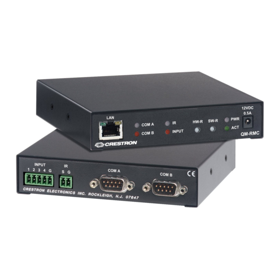
Room Media Controller Physical Description The QM-RMC is housed in a black enclosure with labels on the front and rear panels. On the front of the unit there are six LEDs for indicating the unit’s current status, two LEDs on the LAN connector, and two reset buttons. All connections, except for the Ethernet and power connections, are made on the back of the unit. - Page 9 This green LED illuminates when the unit is connected to and receives 12 VDC power from an external power pack. ACT (LAN) This LED illuminates when the QM-RMC communicates with any device on the network. Operations Guide – DOC. 6161...
- Page 10 Green Yellow 12VDC, 0.5A (Power Supply) 12VDC This male connector can be used to supply 12 VDC power to the QM-RMC 0.5A from an external power pack (included). CAUTION: Use only Crestron power supplies for Crestron equipment. Failure to do so could cause equipment damage or void the Crestron warranty.
-
Page 11: Memory
Crestron QM-RMC Rear Panel Ports The QM-RMC rear panel ports are illustrated and described as follows. INPUT 1 2 3 4 G COM A COM B Memory The QM-RMC has 36MB of built-in memory (non-volatile and volatile). The total of 36MB is specified as follows: 4MB flash (non-volatile), 32MB SDRAM (volatile), and 256KB NVRAM (battery backed up). - Page 12 Flash File Structure Although the file system is case insensitive, the case is preserved to maintain file checksums. Non-volatile 8 • Room Media Processor: QM-RMC 1. SIMPL Program (.smw) 2. SIMPL+ Modules (.usp/.ush) 3. Operating System (.cuz file) TOP LEVEL...
-
Page 13: Industry Compliance
Industry Compliance As of the date of manufacture, the QM-RMC has been tested and found to comply with specifications for CE marking and standards per EMC and Radiocommunications Compliance Labelling (N11785). -
Page 14: Establishing Communication With The Qm-Rmc
Other models, even from the same manufacturer, may not yield the same results. Serial Connection Connect the COM B port on the QM-RMC control system to one of the COM ports (usually COM 1) on the PC. Use a null-modem RS-232 cable with DB9 female connectors on both ends. - Page 15 Open the Crestron Viewport and click Setup | Communication Settings to display the “Port Settings” window. Then click RS-232 as the connection type. NOTE: Changes in communication settings are not saved after the QM-RMC is rebooted. It reverts to default settings.
- Page 16 For TCP/IP, use CAT5 straight through cables with 8-pin RJ-45 connectors to connect the LAN port on the QM-RMC and the LAN port on the PC to the Ethernet hub. Alternatively, you can use a CAT5 crossover cable to connect the two LAN ports directly, without using a hub.
-
Page 17: Troubleshooting Communications
Crestron QM-RMC RJ-45 Pinouts Once the cable connections are made, open the Crestron Viewport and click Setup | Communication Settings on the menu to display the “Port Settings” window. Then click TCP/IP as the connection type. Enter the IP address of the QM-RMC. - Page 18 This will attempt to establish a connection at the indicated baud rate. If the connection is successful, both the PC and the control system will be set to the new baud rate. The QM-RMC will return to its original communication settings when the program reinitializes.
-
Page 19: Compiling And Uploading A Program To The Control System
Compiling and Uploading a Program to the Control System After you have completed your SIMPL Windows program for the QM-RMC, you must compile and upload the program to the control system. To compile the program, simply click the Convert/Compile button SIMPL Windows toolbar, or select Project | Convert/Compile (you can also press F12). -
Page 20: Uploading Web Pages To The Qm-Rmc
In designing and creating a browser project, keep in mind that you must assign an IP ID to all the project pages and specify the IP address of the QM-RMC. (For further information on this procedure, refer to the VT Pro-e online help file.) -
Page 21: Updating The Operating System
As with all Ethernet devices, the PC Interface must receive an entry in the IP Table of the QM-RMC. Here the IP ID must match the IP ID that was assigned in VT Pro-e, while the IP address must be set to a loopback: 127.0.0.1, when hosting internal. -
Page 22: Advanced Console Commands
Downloads | Product Manuals section of the Crestron website (www.crestron.com). Programming the QM-RMC You can create a program that allows you to control the QM-RMC control Have a comment about Crestron system using the Crestron programming tools Crestron Application Builder™... -
Page 23: Programming With The Crestron Appbuilder
Application Builder version 1.2 software for automatic residential and programmer, and much faster commercial programming of the QM-RMC as a control system. As of press for all programmers. However time, this version of Crestron Application Builder had not been released. Please it does not allow the degree of check the Crestron FTP site. - Page 24 IR emitters, splitters, receivers, and remote control transmitters may be required). To add an IR device, drag the device from the Crestron, Project, or User IR Database to the C2I-IR1 port. The Crestron database contains hundreds of IR driver files, covering most IR devices on the market today. The IR port requires one IRP2 (infrared emitter probe) installed on each IR device.
- Page 25 To program a serial driver or serial device expand the C2I-COM-2 in Program View and drag the item to Detail View. Operations Guide – DOC. 6161 • Digitals: <o1> through <o4> Room Media Processor: QM-RMC • 21 Room Media Controller...
- Page 26 Slot 4: C2ENET-1 The C2ENET-1 network interface card provides one LAN port with an RJ-45 connector for connecting the QM-RMC to the Ethernet network. The card provides 252 IP IDs for Ethernet devices. To facilitate network functions and diagnostics, SIMPL Windows provides one device extender for the C2ENET-1 card: Device Status.
- Page 27 A useful feature of SIMPL Windows is that you can convert a program created for another type of control system, simply by changing the target to a QM-RMC. To do this you first open the program, and then replace the existing control system with the QM-RMC.
- Page 28 Selecting a control system means that you are requiring the module to work there. “Module Header Information” Window 24 • Room Media Processor: QM-RMC 3. Save and compile the module by clicking the Save and Compile toolbar button; alternatively, click Save and Compile on the Build menu (or press F12).
-
Page 29: Problem Solving
QM-RMC Troubleshooting System Monitor The System Monitor allows you to reload firmware into the QM-RMC in the event that you cannot load the firmware in the normal mode. Perform the following procedure to correct the “System does not function”... - Page 30 N (Parity), 8 (Data Bits), 1 (Stop Bits), RTS/CTS On, XON/XOFF Off, and click OK. 4. Power down the QM-RMC. 5. While powering up the QM-RMC, press and hold ATL and K on the keyboard until the following text (or similar) appears in Viewport. System Monitor [v1.001 (0001)] 12-19-01 16:25:23 32MB RAM, 4MB FLASH CS>...
- Page 31 The PC is now communicating directly with the device. To exit Passthrough mode, simply click Functions | Exit Passthrough Mode. A system reboot also exits the Passthrough mode. Operations Guide – DOC. 6161 Room Media Controller Room Media Processor: QM-RMC • 27...
-
Page 32: Further Inquiries
Crestron award winning customer service team by calling: Firmware Upgrades To take advantage of all the QM-RMC features, it is important that the unit contains the latest firmware available. Therefore, please check the Crestron website (http://www.crestron.com/downloads/software_updates.asp) for the latest version of firmware. -
Page 33: Software License Agreement
Agreement, which shall remain valid and enforceable according to its terms. This Agreement may only be modified by a writing signed by an authorized officer of Crestron. Updates may be licensed to You by Crestron with additional or different terms. This is the entire agreement between Crestron and You relating to the Software and it supersedes any prior representations, discussions, undertakings, communications or advertising relating to the Software. - Page 34 Crestron or its authorized agents of the Software that deviates from any operating procedures established by Crestron in the material and files provided to You by Crestron or its authorized agent; (3) use of the Software on unauthorized hardware;...
-
Page 35: Return And Warranty Policies
CRESTRON shall not be liable to honor the terms of this warranty if the product has been used in any application other than that for which it was intended, or if it has been subjected to misuse, accidental damage, modification, or improper installation procedures. - Page 36 Crestron Electronics, Inc. Operations Guide – DOC. 6161 15 Volvo Drive Rockleigh, NJ 07647 07.03 Tel: 888.CRESTRON Fax: 201.767.7576 Specifications subject to www.crestron.com change without notice.