
Related Manuals for Omega DRST-FR

Summary of Contents for Omega DRST-FR
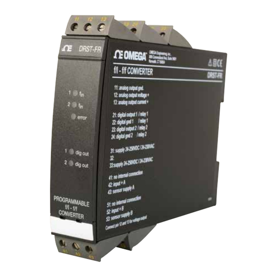
- Page 1 User’s Guide Shop online at omega.com e-mail: info@omega.com For latest product manuals: www.omegamanual.info DRST-FR Programmable Converter...
- Page 2 Fax: (203) 359-7700 e-mail: info@omega.com For Other Locations Visit omega.com/worldwide The information contained in this document is believed to be correct, but OMEGA accepts no liability for any errors it contains, and reserves the right to alter specifications without notice.
-
Page 3: Table Of Contents
Section 11 Status indication ................9 Section 12 Electrical specifications ............. 10 Section 13 Inputs .................... 11 Section 14 Order ..................... 14 Section 15 DRST-FR connection to Loop Link ......... 14 Section 16 Block diagram DRST-FR/A ............15 Section 17 Block diagram DRST-FR/B ............16... -
Page 4: Section 1 Warning
To keep the safety distances, the device must neither be connected to hazardous nor non-hazardous voltages on the same device’s relay contacts. DRST-FR must be mounted on DIN rail according to DIN 46277. The communication connector of DRST-FR is connected to the input terminals on... -
Page 5: Section 2 Symbol Identification
Only technicians who are familiar with the technical terms, warnings, and instructions in the manual and who are able to follow these should connect the device. Should there be any doubt as to the correct handling of the device, please contact Omega Engineering Tech Support. -
Page 6: Section 3 Safety Instructions
When disconnected, the device may be cleaned with a cloth moistened with distilled water. Liability To the extent the instructions in this manual are not strictly observed, the customer cannot advance a demand against Omega A/S that would otherwise exist according to the concluded sales agreement. -
Page 8: Section 5 In General
DRST-FR f/I - f/f converter is configured acc. to the requested function. Alternatively, the DRST-FR may be delivered fully-configured acc. to your specifications, see the options index in the data sheet. Typical pulse sources are flow meters, tacho generators, mechanical switches, or inductive proximity sensors. -
Page 9: Section 7 Technical Characteristics
2 programmable inputs for standard pulse generator connection. Normally, the auxiliary supply and trigger level follow the sensor type, but these can be programmed to other values. At contact input, the 50 Hz filter should be applied. The DRST-FR is protected against polarity reversal on input and supply. -
Page 10: Section 12 Electrical Specifications
Electrical specifications Electrical specifications Specifications range ........-20°C to +60°C Common specifications: Supply voltage . -
Page 11: Section 13 Inputs
Inputs Input: General: Measurement range ....... 0...20 kHz Min. measurement range ....0.001 Hz Max. offset ........90% of selected max. frequency Min. pulse width (without filter) 25 µs Min. period (without filter) ..50 µs Max. frequency (without filter) ..20 kHz Min. - Page 12 Inputs TTL input: Trig-level LOW ....... ≤ 0.8 VDC Trig-level HIGH ......≥ 2.0 VDC Input impedance ......≥ 100 kΩ S0 input acc. to DIN 43 864: Trig-level LOW ....... ≤ 2.2 mA Trig-level HIGH ......≥ 9.0 mA Input impedance ......800 Ω Analogue output: Current output: Signal range ........
- Page 13 V max..........250 VRMS I max..........2 A / AC Max. AC power ......500 VA Max. AC power Ex version DRST-FR: 100 VA Max. load at 24 VDC ..... 1 A. EEx / I.S. approval -DRST-FR: KEMA 04ATEX1001 .......
-
Page 14: Section 14 Order
Order Section 14 - ORDER Type Version Output DRST- Standard : A Analogue + NPN / PNP Analogue + relay output Section 15 - DRST-FR connection to Loop Link Power Loop Link Communications DRST-FR... -
Page 15: Section 16 Block Diagram Drst-Fr/A
Block Diagram DRST-FR /A Section 16 - Block Diagram DRST-FR / A... -
Page 16: Section 17 Block Diagram Drst-Fr/B
NOTES... - Page 17 Displays Section 6.1 - Displays Programmable displays with a wide selection of inputs and outputs for display of temperature, volume and weight, etc. Feature linearization, scaling, and difference measurement functions for programming via OMeset software. 6.2 - EX Interfaces Interfaces for analog and digital signals as well as ®...
- Page 18 Diagrams 6.4 - Temperature A wide selection of transmitters for DIN form B mounting and DIN rail devices with analog and digital bus communication ranging from application- specific to universal transmitters. 6.5 - Universal PC or front programmable devices with universal options for input, output and supply.
- Page 19 Department will issue an Authorized Return (AR) number immediately upon phone or written request. Upon examination by OMEGA, if the unit is found to be defective, it will be repaired or replaced at no charge. OMEGA’s WARRANTY does not apply to defects resulting from any action of the purchaser, including but not limited to mishandling, improper interfacing, operation outside of design limits, improper repair, or unauthorized modification.
- Page 20 Where Do I Find Everything I Need for Process Measurement and Control? OMEGA…Of Course! Shop online at omega.com TEMPERATURE M U Thermocouple, RTD & Thermistor Probes, Connectors, Panels & Assemblies M U Wire: Thermocouple, RTD & Thermistor M U Calibrators & Ice Point References M U Recorders, Controllers &...