
Related Manuals for Crestron C2N-FTB


Summary of Contents for Crestron C2N-FTB
- Page 1 Crestron C2N-FTB FlipTop Control Center with Cresnet ® Operations & Installation Guide...
- Page 2 This document was prepared and written by the Technical Documentation department at: Crestron Electronics, Inc. 15 Volvo Drive Rockleigh, NJ 07647 1-888-CRESTRON All brand names, product names and trademarks are the property of their respective owners. ©2005 Crestron Electronics, Inc.
-
Page 3: Table Of Contents
Identity Code...8 Installation...10 Hardware Hookup ...15 Ground Wire Connections...16 Earliest Version Software Requirements for the PC ...17 Configuring with Crestron SystemBuilder...18 Configuring with SIMPL Windows ...18 Example Program...22 Communication Settings ...23 Uploading a SIMPL Windows Program ...25 Firmware Upgrade ...27 Further Inquiries...29... -
Page 5: Fliptop Control Center With Cresnet
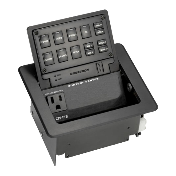
The keypad provides A/V, lighting, and other functional controls via Cresnet The suffix ‘-B’, and ‘-BALUM’, respectively denotes color, e.g., C2N-FTB-B is a black unit, and C2N-FTB-BALUM has a brushed aluminum finish. For simplicity within this guide, color suffix is omitted and the designation C2N-FTB is used except where noted. -
Page 6: Specifications
C2N-FTB Specifications 1. The latest software versions can be obtained from the Crestron website 2. Crestron 2-Series control systems include the AV2 and PRO2. Consult the latest Crestron Product NOTE: Crestron software and any files on the website are for Authorized Crestron dealers and Crestron Authorized Independent Programmers (CAIP) only. -
Page 7: Physical Description
Crestron C2N-FTB Physical Description Refer to the physical views shown below. Top Open View Physical Dimensions Operations & Installation Guide – DOC. 6338 FlipTop Control Center with Cresnet FlipTop Control Center with Cresnet Top View ® ® : C2N-FTB • 3... - Page 8 ® FlipTop Control Center with Cresnet Crestron C2N-FTB Bottom View Physical Dimensions Front View Back View Side View ® 4 • FlipTop Control Center with Cresnet : C2N-FTB Operations & Installation Guide - DOC. 6338...
- Page 9 NOTE: Numbers in this illustration are for programming purposes only. Refer to page 21 for programming information. NOTE: The C2N-FTB is shipped with a set of ten buttons. Additional buttons may be added by ordering button kits (refer to page 10).
-
Page 10: Industry Compliance
Cresnet system or when the device is being added/replaced. Refer to “Method B (Touch Settable ID)” on page 9 for detailed information. Industry Compliance As of the date of manufacture, the C2N-FTB has been tested and found to comply with specifications for CE marking and standards per EMC and Radiocommunications Compliance Labelling. - Page 11 Cresnet power usage of the entire chain. If the unit is a home-run from a Crestron system power supply network port, the Cresnet power usage of that unit is the Cresnet power usage of the entire run. The length of the run in feet and the Cresnet power usage of the run should be used in the resistance equation below to calculate the value on the right side of the equation.
-
Page 12: Identity Code
SIMPL Windows procedure Refer to the note on The Net ID of the C2N-FTB has been factory set to 1E. The Net IDs of multiple page 23 for a C2N-FTBs in the same system must be unique. Net IDs are changed from a definition of personal computer (PC) via the Crestron Viewport. - Page 13 Net ID change. 1. Ensure that all network devices are connected to the control system. 2. Open the Crestron Viewport version 3.35 or later. 3. From the Viewport menu, select Functions | Assign Cresnet ID by Serial Number. The “Set Net ID by TSID” window appears. The window is first displayed with the data fields empty.
-
Page 14: Installation
Alpha characters in serial numbers or TSID numbers may be entered in upper or lower case. Installation The C2N-FTB is shipped with ten large blank buttons. You can order a variety of button kits (sold separately) to add as many as 20 engraved or blank buttons. Button Kits Button Installation To replace the large buttons with small buttons, follow this procedure. - Page 15 Button Installation Cable Management Plate The C2N-FTB is shipped with a cable management plate that provides an eight- hole plate for an easy pullout cable solution for computer, LAN and other passthrough cables.
- Page 16 FlipTop Control Center with Cresnet The cable management plate must be installed before mounting the C2N-FTB to a surface. The cables are looped through the cable support plate. A Phillips screwdriver is required to install the cable management plate. When selecting cables for installation in the C2N-FTB, cable connector length and strain relief diameter are important considerations.
- Page 17 FlipTop box. Mounting to Surface The C2N-FTB is designed to mount in a horizontal surface, such as a desk top, lectern, or podium. The following diagram illustrates the required opening size to accommodate the C2N-FTB. A cutout template (4006405) is included.
- Page 18 FlipTop Control Center with Cresnet Cutout Dimensions Mounting Parts Supplied with the C2N-FTB A Phillips screwdriver is required to mount the C2N-FTB to a surface. NOTE: Before inserting the C2N-FTB in the mounting hole, ensure that all required cables have been installed.
-
Page 19: Hardware Hookup
NOTE: To prevent overheating, do not operate this product in an area that exceeds the environmental temperature range listed in the specifications table. Operations & Installation Guide – DOC. 6338 FlipTop Control Center with Cresnet FlipTop Control Center with Cresnet 3. -
Page 20: Ground Wire Connections
Underside Connections Ground Wire Connections Proper grounding is required. Connect the ground from the C2N-FTB to earth ground. Connect the Cresnet shield lead at the control processor to the ground lead. The control processor chassis must also be connected to an earth ground (building steel). -
Page 21: Configuration Software
Have a question or comment about Crestron software? Answers to frequently asked questions (FAQs) can be viewed in the Online Help section of the Crestron website. To post a question or view questions you have submitted to Crestron’s True Blue Support, log in at http://support.crestron.com. -
Page 22: Configuring With Crestron Systembuilder
The Crestron SystemBuilder then configures the system, including all touchpanel projects and control system logic. It can also connect to Crestron RoomView™ management software. The Crestron SystemBuilder is fully integrated with the Crestron suite of software development tools, including SIMPL Windows, Cross Compiler, VT Pro-e, Crestron Database, User IR Database, and User Modules Directory. - Page 23 To incorporate a C2N-FTB into the system, drag the C2N-FTB from the Wired Keypad folder of the Device Library and drop it in System Views. The PRO2 system tree displays the C2N-FTB in Slot 9, with a default Net ID of 1E as shown in the following illustration.
- Page 24 Crestron C2N-FTB A C2N-FTB in Slot 9 NOTE: The first C2N-FTB in a system is preset with a Net ID of 1E when its symbol is dragged into the upper pane of System Views. Additional units are assigned different Net ID numbers as they are added.
- Page 25 Crestron C2N-FTB C2N-FTB Symbol in Programming Manager The Buttons module is built into the C2N-FTB. It consists of a 10 to 20 button keypad with LED indicators, and two bargraphs. The button presses are fixed and map to <press> outputs on the symbol detail, as follows: NOTE: Numbers in this illustration are for programming purposes only.
-
Page 26: Example Program
FlipTop Control Center with Cresnet C2N-FTB Buttons – Signal Descriptions Example Program An example program for the C2N-FTB is available from the “Example Program” section of the Crestron website (http://www.crestron.com/exampleprograms 22 • FlipTop Control Center with Cresnet ® SIGNAL TYPE AND NAME... -
Page 27: Uploading And Upgrading
All of these functions are accessed through the commands and options in the Viewport menus. Therefore, for its effectiveness as a support and diagnostic tool, the Crestron Viewport may be preferred over development tools when uploading programs and projects. - Page 28 Crestron e-Control Reference Guide (Doc. 6052) or the respective Operations Guide for the control system. These documents are available from the Crestron website. Refer to the following figure for a typical connection diagram when uploading files.
-
Page 29: Uploading A Simpl Windows Program
“Troubleshooting Communications” section in the latest version of the 2-Series Control System Reference Guide (Doc. 6256), which is available from the Crestron website. 1. Start SIMPL Windows. 2. Select File | Open to view the “Open” window, navigate to the SIMPL Window file (.smw), and click Open. - Page 30 FlipTop Control Center with Cresnet Upload via Crestron Viewport File Transfer | Send Program Command NOTE: Refer to the latest version of the Crestron 2-Series Control System Reference Guide (Doc. 6256) for details about the other fields shown on the “Send Program” window.
-
Page 31: Firmware Upgrade
Crestron C2N-FTB Firmware Upgrade A firmware upgrade To take advantage of all the C2N-FTB features, it is important that the unit file has the extension .csf. contains the latest firmware available. Please check the Crestron website for the latest version of firmware. Not every product has a firmware upgrade, but as Crestron improves functions, adds new features, and extends the capabilities of its products, firmware upgrades are posted. - Page 32 28 • FlipTop Control Center with Cresnet ® “Select Network ID” Window “Open” Window 4. Browse to the desired [filename].upg file and click Open to begin the transfer. ® : C2N-FTB Operations & Installation Guide - DOC. 6338 Crestron C2N-FTB...
-
Page 33: Problem Solving
[1-888-273-7876]. For assistance in your local time zone, refer to the Crestron website (www.crestron.com) for a listing of Crestron worldwide offices. You can also log onto the online help section of the Crestron website to ask questions about Crestron products. First-time users will need to establish a user account to fully benefit from all available features. -
Page 34: Return And Warranty Policies
CRESTRON shall not be liable to honor the terms of this warranty if the product has been used in any application other than that for which it was intended, or if it has been subjected to misuse, accidental damage, modification, or improper installation procedures. - Page 35 ® Crestron C2N-FTB FlipTop Control Center with Cresnet This page intentionally left blank. ® : C2N-FTB • 31 Operations & Installation Guide – DOC. 6338 FlipTop Control Center with Cresnet...
- Page 36 Crestron Electronics, Inc. Operations & Installation Guide – DOC. 6338 15 Volvo Drive Rockleigh, NJ 07647 02.05 Tel: 888.CRESTRON Fax: 201.767.7576 Specifications subject to www.crestron.com change without notice.