Olympus EVIS EXERA CLV-160 Instructions Manual
Xenon light source
Hide thumbs
Also See for EVIS EXERA CLV-160:
- Maintenance manual (56 pages) ,
- Maintenance manual (56 pages)
Table of Contents
Advertisement
Advertisement
Table of Contents

Related Manuals for Olympus EVIS EXERA CLV-160


Summary of Contents for Olympus EVIS EXERA CLV-160
- Page 1 INSTRUCTIONS EVIS EXERA XENON LIGHT SOURCE OLYMPUS CLV-160...
-
Page 3: Table Of Contents
Contents Contents Labels and Symbols ..............Important Information — Please Read Before Use....Intended use .................... Instruction manual ..................User qualifications..................Instrument compatibility ................Repair and modification ................Signal words....................Dangers, warnings and cautions .............. Chapter 1 Checking the Package Contents......Chapter 2 Light Source Nomenclature........ - Page 4 Contents Chapter 5 Operation..............Igniting the lamp................Brightness adjustment ..............Using the filter function ..............Using the transillumination function ..........Adjusting air/water pressure............Turning the light source OFF ............Chapter 6 Lamp Replacement..........Lamp life ..................Replacement of the examination (xenon) lamp....... Chapter 7 Care, Storage and Disposal ........
-
Page 5: Labels And Symbols
Labels and Symbols Labels and Symbols Safety-related labels and symbols are attached to the light source at the locations shown below. If labels or symbols are missing or illegible, contact Olympus. Rear side Electrical rating Serial number plate Fuse rating Refer to instructions. - Page 6 Labels and Symbols Back cover of this instruction manual Manufacturer Authorized representative in the European Community EVIS EXERA XENON LIGHT SOURCE CLV-160...
-
Page 7: Important Information - Please Read Before Use
Important Information — Please Read Before Use Intended use This light source has been designed to be used with Olympus endoscopes, and ancillary equipment for observation, diagnosis, endoscopic treatment and recording of image data. Do not use this light source for any purpose other than its intended use. -
Page 8: User Qualifications
Some problems that appear to be malfunctions may be correctable by referring to Chapter 8, “Troubleshooting”. If the problem cannot be resolved using the information in Chapter 8, contact Olympus. EVIS EXERA XENON LIGHT SOURCE CLV-160... -
Page 9: Signal Words
Important Information — Please Read Before Use Signal words The following signal words are used throughout this manual: Indicates an imminently hazardous situation which, if not avoided, will result in death or serious injury. Indicates a potentially hazardous situation which, if not avoided, could result in death or serious injury. - Page 10 − Keep liquids away from all electrical equipment. If fluids are spilled on or into the unit, stop operation of the light source at once and contact Olympus. − Do not prepare, inspect or use this light source with wet hands.
- Page 11 Important Information — Please Read Before Use • Portable or mobile phones may influence the medical electrical equipment by their emitting energy. • Do not use a pointed or hard object to press the switches on the front panel. This may damage the switches. •...
-
Page 12: Chapter 1 Checking The Package Contents
Match all items in the package with the components shown below. Inspect each item for damage. If the light source is damaged, a component is missing or you have any questions, do not use the light source; immediately contact Olympus. Light source (CLV-160) -
Page 13: Chapter 2 Light Source Nomenclature
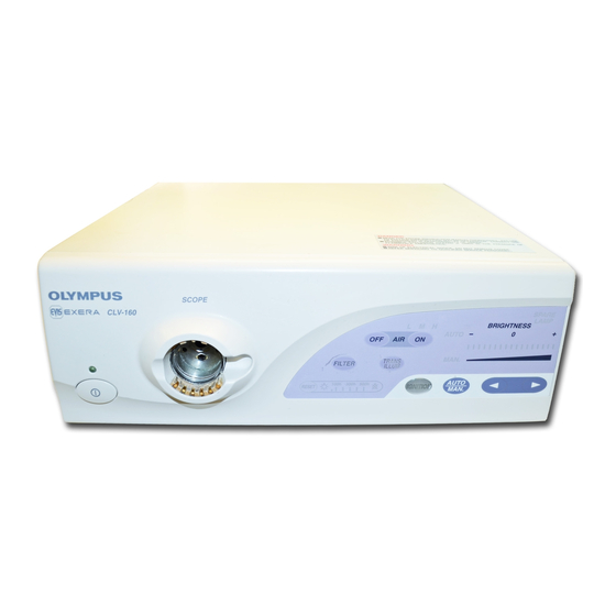
Chapter 2 Light Source Nomenclature Chapter 2 Light Source Nomenclature Front panel 5. Transillumination switch Airflow regulator 4. Filter switch OFF switch 6. Airflow regulator 3. Output socket Airflow regulator switches ON switch 2. Power indicator 7. Airflow indicators 1. Power switch 8. - Page 14 Chapter 2 Light Source Nomenclature 1. Power switch Pressing the power switch in until its stops turns the light source ON. When the power is ON, the power indicator above the power switch is lit. To turn the light source OFF, press the power switch once again. 2.
-
Page 15: Rear And Side Panels
Chapter 2 Light Source Nomenclature Rear and side panels 2. AUX connector AC mains inlet 4. Water container 3. Fuse holders holder 1. Light control connector Rear foot 5. Potential equalization terminal Ventilation grills Rear panel 7. Filter disk 6. Lamp cover Left side EVIS EXERA XENON LIGHT SOURCE CLV-160... - Page 16 Chapter 2 Light Source Nomenclature 1. Light control connector This connector is receptacle for the light control cable to connect the light source to the EVIS EXERA video system center or the EVIS video system center. 2. AUX connector This connector is receptacle for the light control cable to connect the light source to the OES video system.
-
Page 17: Chapter 3 Installation And Connection
Chapter 3 Installation and Connection Chapter 3 Installation and Connection • Turn OFF all system components before connecting them. Otherwise, equipment damage can result. • Use appropriate cables only. Otherwise, equipment damage or malfunction can result. • Use the light source under the conditions described in the “Operating environments”... - Page 18 Chapter 3 Installation and Connection Installation on the mobile workstation Place the mobile workstation on a level surface. Lock the caster brakes as shown in Figure 3.1. Brake caster Brake release Caster Figure 3.1 Install the shelf of the mobile workstation as described in the mobile workstation’s instruction manual.
-
Page 19: Connection Of The Evis Exera Video System Center Or Evis Video System Center
Chapter 3 Installation and Connection Once in position, press the foot holders firmly in place. Place the light source on the mobile workstation so that the feet rest in the foot holders (see Figure 3.3). Video system center Light source (CLV-160) Figure 3.3 Installation in another location... -
Page 20: Connection Of An Endoscope
Chapter 3 Installation and Connection Connection of an endoscope Before connecting the endoscope’s light guide connector to the light source, make sure that it is perfectly dry. If the endoscope’s light guide connector is wet (after disinfecting, for example), wipe and dry the exterior as described in the endoscope’s reprocessing manual. -
Page 21: Installation Of The Water Container
Chapter 3 Installation and Connection To view a fiberscope’s image on a video monitor, prepare an OES video system, such as the OTV-S6. Connect the light control cable supplied with the OES video system to the AUX connector (see Figure 3.6). AUX connector Figure 3.6 Installation of the water container... -
Page 22: Connection To An Ac Mains Power Supply
Chapter 3 Installation and Connection Connection to an AC mains power supply Connect the power plug of the power cord directly to a grounded wall mains outlet. If the light source is not grounded properly, it can cause an electric shock and/or fire. •... -
Page 23: Chapter 4 Inspection
Should the slightest irregularity be suspected, do not use the light source and see Chapter 8, “Troubleshooting”. If the irregularity is still suspected after consulting Chapter 8, contact Olympus. Damage or irregularity may compromise patient or user safety and may result in more severe equipment damage. - Page 24 OFF. Remove the power cord from the wall mains outlet and contact Olympus. Equipment damage or malfunction may have occurred and fire or electric shock can result. Turn the light source OFF and disconnect the power cord from the wall mains outlet.
-
Page 25: Checking The Lamp Life
If the emergency lamp indicator is lit immediately after the light source is turned ON, it is highly likely that the installed emergency lamp is burned out or out of order, contact Olympus. Checking the lamp life Check the lamp life indicator. -
Page 26: Inspection Of The Filter Function
Chapter 4 Inspection Lamp life indicator 500h Figure 4.4 Inspection of the filter function The filter function makes it possible to place a filter of your choice in the light path for special applications. For instructions on selecting and installing a special-purpose filter, see Section 5.3, “Using the filter function”. - Page 27 Chapter 4 Inspection When the light source is already ON, set the filter function to normal observation mode. Turn the light source OFF and disconnect the power cord from the wall mains outlet. Remove the lamp cover and confirm that a special-purpose filter is installed in the filter disk (see Figure 4.5).
-
Page 28: Inspection Of Air And Water Feeding
Chapter 4 Inspection Inspection of air and water feeding When using a water container to feed water from the endoscope, inspect the air and water feeding functions as follows. Confirm that one of the airflow indicators (“L”, “M”, and “H”) is lit. If no indicator is lit, press the airflow regulator ON switch once. -
Page 29: Inspection Of The Examination Light
Chapter 4 Inspection Check the following functions: • Air bubbles are emitted from the air/water nozzle at the distal end of the endoscope. • When the air bubbles are emitted, pressing the airflow regulator OFF switch stops the air bubbles. •... -
Page 30: Inspection Of The Light Decreasing Function
Chapter 4 Inspection Press the lamp ignition switch once. The ignition operation is repeated automatically for up to about 5 seconds until the examination (xenon) lamp ignites. If ignition fails, the light source automatically switches to the emergency (halogen) lamp and the emergency lamp indicator is lit. If this happens, turn the light source OFF and ON again. -
Page 31: Inspection Of Transillumination Function
Chapter 4 Inspection Inspection of transillumination function When using a fiberscope without video or TV systems, do not use the transillumination function while looking into the eyepiece of the endoscope. Using this function sets the examination light to maximum, and eye damage can result. The transillumination function allows to externally confirm the endoscope’s position in the patient’s body due to more intense examination light emitted from the endoscope’s distal end. -
Page 32: Inspection Of Brightness Adjustment
Chapter 4 Inspection Inspection of brightness adjustment When using the fiberscope without video or TV systems, set the auto/manual brightness selector to “MAN.”. Setting to “AUTO” changes the examination light to maximum, and eye damage can result. Selecting automatic or manual brightness control When selecting a brightness control mode, confirm that the corresponding indicator lights up when pressing the auto/manual brightness selector (see Figure 4.10) and a beep is heard. - Page 33 Chapter 4 Inspection Automatic brightness adjustment Before disconnecting the video system from the endoscope, always select manual brightness control and set the brightness to minimum. If the video system is disconnected while the brightness adjustment is set to automatic, examination light may change to maximum and eye damage can result.
- Page 34 Chapter 4 Inspection Brightness level indicators Brightness adjustment switches Figure 4.12 Manual brightness adjustment When using manual brightness adjustment, always set the brightness to the minimum level necessary to complete the examination. If the light is too bright, eye damage or burns can result.
-
Page 35: Chapter 5 Operation
And then, contact Olympus. • Anytime you suspect an abnormality in a light source function, stop the examination immediately. Take action according to the procedures described below. - Page 36 MRI equipment or radio). Brightness fluctuation can occur. • It is recommended to use only Olympus high frequency electrosurgical equipment with this unit. Non-Olympus equipment can cause interference on the monitor display or a loss of the endoscopic image.
-
Page 37: Igniting The Lamp
Chapter 5 Operation Igniting the lamp Confirm that the endoscope is connected to the output socket, and press the power switch (see Figure 5.1). Output socket Lamp ignition Power switch switch Figure 5.1 Press the lamp ignition switch to ignite the examination lamp. Brightness adjustment •... - Page 38 Chapter 5 Operation Adjust the brightness of the video monitor. Operating the automatic brightness adjustment Before disconnecting the video system from the endoscope, always select manual brightness adjustment and set the brightness to minimum. If the video system is disconnected while the brightness adjustment is set to automatic, examination light may change to maximum and eye damage or burns can result.
-
Page 39: Using The Filter Function
Chapter 5 Operation Operating the manual brightness adjustment • When using manual brightness adjustment, always set the brightness to the minimum level necessary to complete the examination. If the brightness is set higher than necessary, eye damage or burns can result. •... - Page 40 • If the filter falls into the light source, turn it OFF immediately, disconnect the power cord and contact Olympus. If the light source is used with the filter left inside of it, an electric shock and/or fire may result.
- Page 41 Chapter 5 Operation Align the filter’s frame installed a special-purpose filter with the groove in the filter disk, and push the filter’s frame into the filter disk until it locks (see Figure 5.4). Lamp cover Filter disk Filter’s frame Special-purpose filter Figure 5.4 Close the lamp cover securely.
-
Page 42: Using The Transillumination Function
Chapter 5 Operation Using the transillumination function • Do not use the transillumination function unless absolutely necessary. Otherwise, eye damage or burns can result. • When using a fiberscope without video or TV systems, do not use the transillumination function while looking into the eyepiece of the endoscope. -
Page 43: Adjusting Air/Water Pressure
Chapter 5 Operation Adjusting air/water pressure Confirm that one of the airflow indicators (“L”, “M”, or “H”) is lit. If no indicator is lit, press the airflow regulator ON switch to set the airflow regulator to “L”, “M” or “H”. The standard air pressure is “H”. -
Page 44: Chapter 6 Lamp Replacement
If the wrench falls inside the light source, turn OFF the light source immediately, disconnect the power cord and contact Olympus. If the light source is used while the wrench is detached inside the light source, equipment damage and/or electrical shock can result. - Page 45 Chapter 6 Lamp Replacement • Never install a lamp that has not been approved by Olympus. The use of a non-approved lamp can cause damage to the light source and ancillary equipment, malfunction or fire. • Do not apply shock, excessive force or scratches to the lamp.
- Page 46 To replace the examination lamp, follow the procedure given below. Use the examination lamp MD-631 only. To order a new examination lamp, contact Olympus. Turn the light source OFF and disconnect the power cord. If the lamp was in use immediately, the lamp chamber is extremely hot. Cool the lamp chamber down by turning the light source OFF and ON again.
- Page 47 Chapter 6 Lamp Replacement Insertion groove Heat sink (A) Heat sink (B) Knob (B) Knob (A) Figure 6.3 Using the hexagon wrench, loosen the three bolts on heat sink (B) (on the “+” side of the examination lamp or heat sink (B)) and remove heat sink (B) from the examination lamp (see Figure 6.4).
- Page 48 Chapter 6 Lamp Replacement Hold the new examination lamp without touching the glass surface. • Do not apply the heat compound to the glass surface and the ceramic part of the examination lamp. If any compound gets on the glass surface, wipe it off with a clean lint-free cloth. •...
- Page 49 Chapter 6 Lamp Replacement Make sure that the undersides of the heat sinks (A) and (B) are flat, and close the clamp of heat sink (A). Turn the knobs of heat sinks (A) and (B) to the horizontal position, and insert the heat sinks all the way into the lamp chamber along the insertion grooves.
- Page 50 Chapter 6 Lamp Replacement Turn ON the light source. Then press the reset switch for at least 3 seconds until all lamp life indicators are OFF. Lamp life indicators Reset switch Figure 6.8 If the light source is to be used immediately, proceed with the inspection of the light source as described in Chapter 4, “Inspection”.
- Page 51 Chapter 6 Lamp Replacement EVIS EXERA XENON LIGHT SOURCE CLV-160...
-
Page 52: Chapter 7 Care, Storage And Disposal
Chapter 7 Care, Storage and Disposal Chapter 7 Care, Storage and Disposal Care • After wiping with a piece of moistened gauze, dry the light source thoroughly before using it again. If it is used while still wet, there is the risk of an electrical shock. •... -
Page 53: Storage
Chapter 7 Care, Storage and Disposal Storage Do not store the light source in a location exposed to direct sunlight, X-rays, radioactivity or strong electromagnetic radiation (e.g., near microwave medical treatment equipment, short-wave medical treatment equipment, MRI equipment or radio). Damage to the light source may result. Turn the light source OFF and disconnect the power cord. -
Page 54: Chapter 8 Troubleshooting
Some problems that appear to be malfunctions may be correctable by referring to Section 8.1, “Troubleshooting guide”. If the problem cannot be resolved by the described remedial action, stop using the light source and send it to Olympus for repair. - Page 55 Chapter 8 Troubleshooting Irregularity Possible cause Solution description The examination The examination lamp has not been Press the lamp Ignition lamp does not ignited yet. switch. ignite. The examination lamp is not installed. Install an examination lamp as described in Section 6.2, page 40.
- Page 56 Chapter 8 Troubleshooting Irregularity Possible cause Solution description The field of view The examination lamp is old. Replace the and the image are examination lamp with too dark or too a new one as bright. described in Section 6.2, page 40. The emergency lamp is active.
- Page 57 Chapter 8 Troubleshooting Irregularity Possible cause Solution description The field of view The emergency lamp is active. Replace the and image color are examination lamp with poor. a new one as described in Section 6.2, page 40. The filter mode is activated. Press the filter switch (The filter switch is lit.) to change to the...
-
Page 58: Returning The Light Source For Repair
Olympus is not liable for any injury or damage which occurs as a result of repairs attempted by non-Olympus personnel. When returning the light source for repair, contact Olympus. With the light source, include a description of the malfunction or damage and the name and telephone number of the individual at your location who is most familiar with the problem. -
Page 59: Appendix
New products released after the introduction of this light source may also be compatible for use in combination with this light source. For further details, contact Olympus. If combinations of equipment other than those shown below are used, the full responsibility is assumed by the medical treatment facility. - Page 60 Appendix EVIS system chart Video monitor (OEV203, 202, 201) (OEV143, 142, 141) Keyboard Light control cable EVIS video system center (MH-966) (CV-140) EVIS EXERA video system center (CV-160) Videoscope (See the next page.) Videoscope cable EXERA Videoscope cable (See the next page.) Water container EVIS EXERA (See the next page.)
- Page 61 Appendix Videoscope cable EXERA/videoscope cable Videoscope cable EXERA/Videoscope cable EVIS EXERA video system center/ EVIS video system center MAJ-843 MH-976 MD-148 CV-160 – CV-140 applicable – not applicable Water container Water container Endoscope MAJ-901 MAJ-902 MH-884 MH-970 MD-431 MA-995 – –...
- Page 62 Appendix OES system chart Video monitor (OEV203, 202, 201) (OEV143, 142, 141) Mobile workstation (WM-30, WM-N60) Light control cable (MAJ-586) OES videosystem (OTV-S6) Videoadapter (A10-T1/T2) EVIS EXERA xenon light source Fiberscope (CLV-160) (See below.) Water container (See below.) Water container Water container Endoscope MAJ-901...
-
Page 63: Operating Environment
Appendix Operating environment Operating Ambient 10 – 40°C (50 – 104°F) environment temperature Relative humidity 30 – 85% Air pressure 700 – 1060 hPa (0.7 – 1.1 kgf/cm (10.2 – 15.4 psia) Transportation and storage environment Transportation and Ambient –25 to +85°C storage environment temperature (–13 to +185°F) -
Page 64: Specifications
Appendix Specifications Item Specification Power supply Voltage 100 – 120 V AC Within ±10% Power fluctuation Frequency 50/60 Hz Frequency Within ±1 Hz fluctuation Input current Fuse rating 8 A, 250 V Fuse size 6.35 × 31.8 mm Size Dimensions 385 (W) ×... - Page 65 Appendix Item Specification Automatic Automatic brightness brightness control Servo-diaphragm method control method Automatic exposure 17 steps Air feeding Pump Diaphragm type pump Pressure switching 4-level available (off, low, mid, high) Water feeding Method Air pressurization or detachable water container Indicators on Emergency lamp It reports absence of emergency lamp, front panel...
- Page 67 ©2000 OLYMPUS MEDICAL SYSTEMS CORP. All rights reserved. No part of this publication may be reproduced or distributed without the express written permission of OLYMPUS MEDICAL SYSTEMS CORP. OLYMPUS is a registered trademark of OLYMPUS CORPORATION. Trademarks, product names, logos, or trade names used in this document are generally registered trademarks or trademarks of each company.
- Page 68 Manufactured by 2951 Ishikawa-cho, Hachioji-shi, Tokyo 192-8507, Japan Fax: (042)646-2429 Telephone: (042)642-2111 Distributed by 3500 Corporate Parkway, P.O. Box 610 Center Valley, PA 18034-0610, U.S.A. Fax: (484)896-7128 Telephone: (484)896-5000 One Corporate Drive, Orangeburg, N.Y. 10962, U.S.A. Fax: (845)398-9444 Telephone: (845)398-9400 5301 Blue Lagoon Drive, Suite 290 Miami, FL 33126-2097, U.S.A.