
Related Manuals for Pentair Schroff AdvancedTCA 11596-100


Summary of Contents for Pentair Schroff AdvancedTCA 11596-100
- Page 1 AdvancedTCA Shelf, 14-slot Service Manual Product Numbers: 11596-100 11596-101 11596-102 11596-103 Revision: R1.1, July 23, 2008 Doc-No: 63972-171...
- Page 2 Rev. Date updated Change R1.0 November 24, 2006 Initial Release R1.1 July 23, 2006 Chapter 3.4 added Impressum: Schroff GmbH D-75334 Straubenhardt, Germany The details in this manual have been carefully compiled and checked - supported by certified Quality Management System to EN ISO 9001/2000 The company cannot accept any liability for errors or misprints.
-
Page 3: Table Of Contents
14-Slot AdvancedTCA Shelf 11596-100/-101/-102/-103 Table of Contents Safety ......................... 1 Safety Symbols used in this document..............1 General Safety Precautions................. 1 References and Architecture Specifications ............2 Product Definition ....................2 ESD Wrist Strap Terminals.................. 3 Terms and Acronyms................... 4 Shelf Overview .................... - Page 4 14-Slot AdvancedTCA Shelf 11596-100/-101/-102/-103 Shelf Alarm Panel (SAP) Replacement ............. 31 Chassis Data Module (CDM) Replacement............31 Shelf Manager Replacement ................33 4.10 ShMM-500 Replacement ................... 34 4.11 Insertion of ATCA Boards .................. 35 4.12 Part Numbers..................... 36 www.a-tca.com / www.schroff.biz R1.1, July 23, 2008...
-
Page 5: Safety
14-Slot AdvancedTCA Shelf Safety 11596-100/-101/-102/-103 1 Safety The intended audience of this Service Manual is system integrators and qualified service personnel. The instructions in this manual primarily describe the installation and maintenance of the 14-Slot ATCA Shelf. When installing racks, electrical wiring and other equipment, you should follow all local, state, federal, or international codes and regulations. -
Page 6: References And Architecture Specifications
14-Slot AdvancedTCA Shelf Safety 11596-100/-101/-102/-103 1.3 References and Architecture Specifications ® • PICMG 3.0 AdvancedTCA® Base Specification (www.picmg.com) ® • PICMG Engineering Change Notice ECN 3.0-2.0-00 • User’s Manual for the 11596-10x ATCA Shelves, Doc-No.: 63972-172 1.4 Product Definition The Schroff 11596-10x is a 13U / 14 Slot Shelf and designed according to AdvancedTCA standards. -
Page 7: Esd Wrist Strap Terminals
14-Slot AdvancedTCA Shelf Safety 11596-100/-101/-102/-103 1.5 ESD Wrist Strap Terminals Danger of electrostatic discharge! Static electricity can harm delicate components inside the Shelf. You must wear an ESD wrist strap before exchanging any part or electric component! Two ESD Wrist Strap Terminals are located at the lower front and rear side of the Shelf. -
Page 8: Terms And Acronyms
14-Slot AdvancedTCA Shelf Safety 11596-100/-101/-102/-103 1.6 Terms and Acronyms Table 1: Terms and Acronyms Term Definition ATCA Advanced Telecom Computing Architecture Backplane Passive circuit board providing the connectors for the front boards. Power distribution, management and auxiliary signal connections are supported Chassis Data Module Chassis Enclosure containing subrack, Backplane, boards, cooling devices, PEMs, same as Shelf... -
Page 9: Shelf Overview
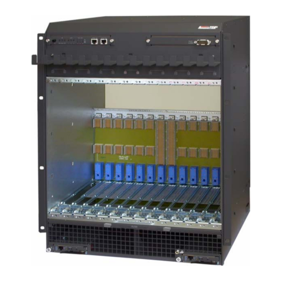
14-Slot AdvancedTCA Shelf Shelf Overview 11596-100/-101/-102/-103 2 Shelf Overview Figure 2: Shelf Front View 12706961 Shelf Alarm Display (SAD) Shelf Alarm Panel (SAP) ATCA 14-Slot Backplane Front Cable Tray Front Card Cage Removable Mounting Bracket Air Filter ESD Wrist Strap Terminal Shelf Manger 1 (left) Shelf Manager 2 (right) Transportation Lock... - Page 10 14-Slot AdvancedTCA Shelf Shelf Overview 11596-100/-101/-102/-103 Figure 3: Shelf Rear View 12706887 Fan Tray #2 Fan Tray #0 Rear Card Cage Rear Cable Tray ESD Wrist Strap Terminal Shelf Ground Terminal (M6 studs) Power Entry Module B (PEM B) Power Entry Module A (PEM A) Fan Tray #1 www.a-tca.com / www.schroff.biz R1.1, July 23, 2008...
- Page 11 14-Slot AdvancedTCA Shelf Shelf Overview 11596-100/-101/-102/-103 Figure 4: Shelf mechanical dimensions, front view 12706905 All dimensions are in millimeters (mm). www.a-tca.com / www.schroff.biz R1.1, July 23, 2008...
- Page 12 14-Slot AdvancedTCA Shelf Shelf Overview 11596-100/-101/-102/-103 Figure 5: Shelf mechanical dimensions, side view 12706906 All dimensions are in millimeters (mm). www.a-tca.com / www.schroff.biz R1.1, July 23, 2008...
- Page 13 14-Slot AdvancedTCA Shelf Shelf Overview 11596-100/-101/-102/-103 Table 2: Technical Data Physical Dimensions Height 571.6 mm Width 482.6 mm Depth 506.54 mm (with cable trays) Weight Shipping weight completely assembled 45 Kg with packaging Shelf weight (w/o fan tray and w/o PEMs) 19 Kg Shelf weight completely assembled 30.6 Kg...
-
Page 14: Shelf Installation
14-Slot AdvancedTCA Shelf Shelf Installation 11596-100/-101/-102/-103 3 Shelf Installation Install the system in a restricted access area, where access can be gained only by service personnel through the use of a special tool, lock and key, or other means of security. Choose a site with a dry, clean, well-ventilated and air-conditioned area that maintains an ambient temperature of 5°C to 45°C (41°F to 113°F). -
Page 15: Unpacking
14-Slot AdvancedTCA Shelf Shelf Installation 11596-100/-101/-102/-103 3.1 Unpacking Caution! When opening the shipping carton, use caution to avoid damaging the Shelf. Danger of electrostatic discharge! The Shelf contains static sensitive devices. While unpacking and handling the Shelf you must wear an ESD wrist strap to prevent static damage. Caution! Do NOT use the Fan Tray and PEM handles or cable trays as lifting points. -
Page 16: Rack-Mounting
14-Slot AdvancedTCA Shelf Shelf Installation 11596-100/-101/-102/-103 3.2 Rack-Mounting Warning! Do NOT move the Shelf by yourself. Due to the height and weight of the Shelf, at least two persons are needed to accomplish this task. We recommend to use a mechanical lift or remove all hot-swappable equipment for weight reduction. - Page 17 14-Slot AdvancedTCA Shelf Shelf Installation 11596-100/-101/-102/-103 Mounting Instructions: • Ensure that the rack is constructed to support the weight and dimensions of the Shelf. • Install any stabilizers that came with your equipment rack before mounting or servicing the system in the rack. •...
-
Page 18: Mounting Bracket Swap
14-Slot AdvancedTCA Shelf Shelf Installation 11596-100/-101/-102/-103 3.3 Mounting Bracket Swap Figure 7: Removable Mounting Brackets 12706857 You can swap the mounting brackets (1) from position (A) to (B). Mounting brackets swap: 1 Unscrew the locking screws (2). 2 Push the mounting bracket downwards to disengage the locking. 3 Turn the mounting bracket at 180°... -
Page 19: Additional Rear Fixing Points
14-Slot AdvancedTCA Shelf Shelf Installation 11596-100/-101/-102/-103 3.4 Additional Rear Fixing Points The Shelf provides two additional rear fixing points. These points can be used to enhance the shock and vibration stability. Because the rear fixing points are not standardized, the respective mounting brackets must be manufactured by the customer. -
Page 20: Shelf Ground Connection
14-Slot AdvancedTCA Shelf Shelf Installation 11596-100/-101/-102/-103 3.5 Shelf Ground Connection Warning! This Shelf is intended to be grounded. Ensure that the Shelf Ground terminals are connected to Protective Earth (PE) of the building. Danger of electrostatic discharge! Static electricity can harm delicate components inside the Shelf. You must wear an ESD wrist strap before exchanging any part or electric component! The Shelf must be properly grounded via the Shelf Ground Terminal. -
Page 21: Shelf Power Connection
14-Slot AdvancedTCA Shelf Shelf Installation 11596-100/-101/-102/-103 3.6 Shelf Power Connection Hazardous voltage! Before working ensure that the power is removed from the power connection cables. When the system is powered on, do NOT touch the power terminals! Warning! Avoid electric overload. To avoid electrical hazard, do not make connections to terminals outside the specified voltage range for that Shelf. -
Page 22: Installation The Power Connection Cables
14-Slot AdvancedTCA Shelf Shelf Installation 11596-100/-101/-102/-103 Figure 11: PEM components 12706901 Terminal Cover Table 3: PEM Input Power Terminal Terminal -48/-60 VDC# Designation Terminal RTN# Designation Power Input Feed 1 Return Voltage Feed 1 Power Input Feed 2 Return Voltage Feed 2 Power Input Feed 3 Return Voltage Feed 3 Power Input Feed 4... -
Page 23: Initial Operation
14-Slot AdvancedTCA Shelf Shelf Installation 11596-100/-101/-102/-103 3.9 Initial Operation Before installing the ATCA boards ensure that there is no transport damage and the system is fully operational. Apply power to PEM A and PEM B and watch the boot-up process. Boot-up process: 1 All of the LEDs on the Shelf Alarm Display, the Shelf Manager, the Fan Trays an the PEMs turn on, the fans are spinning with full speed... -
Page 24: Logic Ground To Shelf Ground Connection
14-Slot AdvancedTCA Shelf Shelf Installation 11596-100/-101/-102/-103 3.10 Logic Ground to Shelf Ground connection Figure 12: Logic Ground/Shelf Ground Connection 12706816 The ATCA Backplane provides a mechanism to connect Logic Ground (GND) and Shelf Ground (Shelf_GND). You can connect/isolate Logic Ground by swapping two screws from position (A) to position (B). -
Page 25: Maintenace
14-Slot AdvancedTCA Shelf Maintenace 11596-100/-101/-102/-103 4 Maintenace 4.1 Accessing the Shelf Management Software You can access to the Shelf Management software either remotely through ethernet (Tenet, SSH) or by connecting a terminal console directly to the Shelf Manager’s serial console interface (RJ45) on the Shelf Alarm Panel (SAP). Note: By default the ethernet connector at the Shelf Manager frontpanel is not in service but jumper configurable. -
Page 26: Basic Cli Commands
14-Slot AdvancedTCA Shelf Maintenace 11596-100/-101/-102/-103 4.1.2 Basic CLI Commands Service personnel can read system information, FRU information and sensor data with the following basic commands. For a full list of all CLI commands refer to the Firmware User Manual. • Change IP address of the primary Shelf Manager: clia setlanconfig channel ip value Value represents the IP address in dotted decimal notation. -
Page 27: Telco Alarms
14-Slot AdvancedTCA Shelf Maintenace 11596-100/-101/-102/-103 4.2 Telco Alarms 4.2.1 Telco Alarm Interface The SAP provides a Telco Alarm interface on the DB15-male connector. Three relay outputs are used for remote alarm distribution, reflecting the state of the three Alarm LEDs. The relays are capable of carrying 72 VDC or 1 A with a max. -
Page 28: Air Filter Replacement
14-Slot AdvancedTCA Shelf Maintenace 11596-100/-101/-102/-103 4.3 Air Filter Replacement Danger of electrostatic discharge! Static electricity can harm delicate components inside the Shelf. You must wear an ESD wrist strap before exchanging any part or electric component! Figure 14: Air Filter 12706958 Filter Element Filter Tray... -
Page 29: Power Entry Module (Pem) Replacement
14-Slot AdvancedTCA Shelf Maintenace 11596-100/-101/-102/-103 4.4 Power Entry Module (PEM) Replacement Hazardous voltage! Before disconnecting the power cables ensure that the power is removed from the power cables. When the system is powered on, do NOT touch the power terminals! Warning! This Shelf is intended to be grounded. - Page 30 14-Slot AdvancedTCA Shelf Maintenace 11596-100/-101/-102/-103 Figure 15: PEM components 12706901 Hot Swap Push Button Terminal Cover Hot Swap LED Handles PEM Alarm LED PEM Fixing Screws PEM OK LED Shelf Ground Terminal Remove PEM 1 Ensure that the redundant PEM is fully functional (red Alarm LED is off). 2 Push Hot Swap Push Button (1) until Hot Swap LED (2) starts blinking.
- Page 31 14-Slot AdvancedTCA Shelf Maintenace 11596-100/-101/-102/-103 Figure 16: 12706849 Fixing Screws Slots Guides Install PEM: 1 Insert the PEM into the Shelf. The slots (11) must slide into the guides (10). Note: The blue Hot Swap LED (2) starts blinking until the PEM is fully functional.
-
Page 32: Pem Fuse Replacement
14-Slot AdvancedTCA Shelf Maintenace 11596-100/-101/-102/-103 4.4.1 PEM Fuse Replacement All four Power Feeds are protected by a fuse in the -48 V and in the VRTN path. All fuses have a rating of 30 A/80 V. To replace a fuse you have to remove the resp. PEM first. See Chapter 4.4, "Power Entry Module (PEM) Replacement"... -
Page 33: Fan Tray Replacement
14-Slot AdvancedTCA Shelf Maintenace 11596-100/-101/-102/-103 4.5 Fan Tray Replacement Danger of electrostatic discharge! Static electricity can harm delicate components inside the Shelf. You must wear an ESD wrist strap before exchanging any part or electric component! Figure 18: Fan Tray 12706991 Hot Swap Push Button Fan Tray OK LED (green) -
Page 34: Shelf Alarm Display (Sad) Replacement
14-Slot AdvancedTCA Shelf Maintenace 11596-100/-101/-102/-103 4.6 Shelf Alarm Display (SAD) Replacement Danger of electrostatic discharge! Static electricity can harm delicate components inside the Shelf. You must wear an ESD wrist strap before exchanging any part or electric component! Figure 19: Shelf Alarm Display (SAD) 12706852 Shelf Alarm Display Guides... -
Page 35: Shelf Alarm Panel (Sap) Replacement
14-Slot AdvancedTCA Shelf Maintenace 11596-100/-101/-102/-103 4.7 Shelf Alarm Panel (SAP) Replacement For instructions see Chapter 4.6, "Shelf Alarm Display (SAD) Replacement". Figure 20: Shelf Alarm Panel (SAP) 12706962 4.8 Chassis Data Module (CDM) Replacement The Chassis Data Modules (CDMs) are located on the Backplane behind the Power Entry Modules (PEMs). - Page 36 14-Slot AdvancedTCA Shelf Maintenace 11596-100/-101/-102/-103 Figure 21: Chassis Data Modules (CDMs) 12706915 CDM 1 Slot CDM 2 Fixing Screw Remove: 1 Remove the resp. PEM. Note: See instructions in Chapter 4.4, "Power Entry Module (PEM) Replace- ment". 2 Remove the fixing screw (4). Note: Use a magnetic screwdriver to prevent the fixing screw from falling into the Shelf! 3 Push the CDM in direction of the arrow to release the locking mechanism in...
-
Page 37: Shelf Manager Replacement
14-Slot AdvancedTCA Shelf Maintenace 11596-100/-101/-102/-103 4.9 Shelf Manager Replacement Danger of electrostatic discharge! Static electricity can harm delicate components inside the Shelf. You must wear an ESD wrist strap before exchanging any part or electric component! Figure 22: Shelf Manager 12706850 Fixing Screw Status LED (green) -
Page 38: Shmm-500 Replacement
14-Slot AdvancedTCA Shelf Maintenace 11596-100/-101/-102/-103 4.10 ShMM-500 Replacement Danger of electrostatic discharge! Static electricity can harm delicate components inside the Shelf. You must wear an ESD wrist strap before exchanging any part or electric component! Figure 23: ShMM-500 Replacement 12706992 To replace the ShMM-500 you have to remove the Shelf Manager first. -
Page 39: Insertion Of Atca Boards
14-Slot AdvancedTCA Shelf Maintenace 11596-100/-101/-102/-103 4.11 Insertion of ATCA Boards Danger of electrostatic discharge! Static electricity can harm delicate components inside the Shelf. You must wear an ESD wrist strap before exchanging any part or electric component! Figure 24: Insertion of ATCA Boards 12706916 Caution! When installing Front boards or RTM boards, ensure that the board slides into... -
Page 40: Part Numbers
14-Slot AdvancedTCA Shelf Maintenace 11596-100/-101/-102/-103 4.12 Part Numbers Table 5: Part Numbers Number Part 11596-100 14-Slot ATCA Shelf, Dual Star Backplane, bused IPMB 11596-101 14-Slot ATCA Shelf, Dual Star Backplane, radial IPMB 11596-102 14-Slot ATCA Shelf, Full Mesh Backplane, bused IPMB 11596-103 14-Slot ATCA Shelf, Full Mesh Backplane, radial IPMB 21593-375... - Page 42 SCHROFF GMBH www.schroff.biz www.a-tca.com Langenalberstr. 96-100 Tel.: + 49 (0) 7082 794-0 Fax: +49 (0) 7082 794-200 D-75334 Straubenhardt...