Table of Contents
Advertisement
Available languages
Available languages
Quick Links
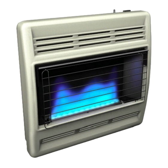
UNVeNTed (VeNT-FRee) BlUe FlaMe Gas HeaTeR
saFeTY INFoRMaTIoN aNd INsTallaTIoN MaNUal
WARNING: If the information in this manual is not
followed exactly, a fire or explosion may result causing
property damage, personal injury or loss of life.
— Do not store or use gasoline or other flammable va-
pors and liquids in the vicinity of this or any other
appliance.
— WHAT TO DO IF YOU SMELL GAS
• Do not try to light any appliance.
• Do not touch any electrical switch; do not use any
phone in your building.
• Immediately call your gas supplier from a neighbor's
phone. Follow the gas supplier's instructions.
• If you cannot reach your gas supplier, call the fire
department.
— Installation and service must be performed by a quali-
fied installer, service agency or the gas supplier.
INSTALLER: Leave this manual with the appliance.
CONSUMER: Retain this manual for future reference.
For more information, visit www.desatech.com
Models VN20BTB, VP20BTB
VN30BTB aNd VP30BTB
Advertisement
Chapters
Table of Contents

Related Manuals for Desa VN20BTB


Summary of Contents for Desa VN20BTB
- Page 1 UNVeNTed (VeNT-FRee) BlUe FlaMe Gas HeaTeR saFeTY INFoRMaTIoN aNd INsTallaTIoN MaNUal Models VN20BTB, VP20BTB VN30BTB aNd VP30BTB WARNING: If the information in this manual is not followed exactly, a fire or explosion may result causing property damage, personal injury or loss of life.
-
Page 2: Table Of Contents
TaBle oF CoNTeNTs Safety ..............2 Cleaning ............16 Local Codes............4 Troubleshooting ..........17 Unpacking............4 Specifications ............ 21 Product Identification ........... 4 Service Hints ............. 21 Product Features ..........4 Technical Service..........21 Air For Combustion and Ventilation ..... 5 Service Publications .......... -
Page 3: Safety
saFeTY Keep the appliance area clear Continued and free from combustible ma- terials, gasoline and other flam- Natural and Propane/LP Gas: Natural and propane/LP gases are fuel gases. Fuel gases mable vapors and liquids. are odorless. An odor-making agent are add- ed to fuel gases. -
Page 4: Local Codes
1. Remove heater from carton. 2. Remove all protective packaging applied to heater for shipment. 3. Check heater for any shipping damage. If heater is damaged, promptly return to dealer where you bought heater or call DESA Heating, LLC at 1-866-672-6040. www.desatech.com 121880-01B... -
Page 5: Air For Combustion And Ventilation
aIR FoR CoMBUsTIoN aNd VeNTIlaTIoN Unusually Tight Construction WARNING: This heater shall The air that leaks around doors and windows not be installed in a confined may provide enough fresh air for combustion and ventilation. However, in buildings of un- space or unusually tight con- usually tight construction, you must provide struction unless provisions are... - Page 6 aIR FoR CoMBUsTIoN aNd VeNTIlaTIoN Continued DETERMINING FRESH-AIR FLOW 4. Compare the maximum Btu/Hr the space can support with the actual amount of Btu/Hr FOR HEATER LOCATION used. Determining if You Have a Confined or ________ Btu/Hr (maximum can support) Unconfined Space ________ Btu/Hr (actual amount used) Use this work sheet to determine if you have a...
-
Page 7: Installation
aIR FoR CoMBUsTIoN Ventilated aNd VeNTIlaTIoN Outlet Attic Continued Outlet vENTILATION AIR To Attic Ventilation Air From Inside Building This fresh air would come from an adjoining Crawl unconfined space. When ventilating to an Space Inlet adjoining unconfined space, you must provide two permanent openings: one within 12"... - Page 8 INsTallaTIoN WARNING: Never install the Continued heater INSTALLATION ITEMS • in a bedroom or bathroom Before installing heater, make sure you have • in a recreational vehicle the items listed below. • where curtains, furniture, • for propane/LP gas, external regulator clothing or other flammable (supplied by installer) objects are less than 36"...
- Page 9 INsTallaTIoN Methods For Attaching Mounting Bracket To Wall Continued Only use last hole on each end of mounting THERMOSTAT SENSING BULB bracket to attach bracket to wall. These two The thermostat sensing bulb has been placed holes are 14" apart from their centers. Attach below the heater.
- Page 10 INsTallaTIoN 6. Insert mounting screws through bracket and into wall anchors. Continued 7. Tighten screws until mounting bracket is Attaching Mounting Bracket To Wall firmly fastened to wall. Note: Wall anchors, mounting screws and Placing Heater On Mounting Bracket spacers are in hardware package. The hard- 1.
- Page 11 INsTallaTIoN Mounting Base Feet to Floor 1. Remove front cover (see Removing Front Continued Panel of Heater, page 9). 4. If installing bottom mounting screws into 2. Position heater with base feet in desired hollow or solid wall, install wall anchors. location.
- Page 12 INsTallaTIoN Install sediment trap in supply line as shown in Figure 15. Locate sediment trap where it Continued is within reach for cleaning. Locate sediment For propane/LP gas, the installer must supply trap where trapped matter is not likely to an external regulator.
- Page 13 INsTallaTIoN Test Pressures Equal To or Less Than 1/2 PSIG (14" w.c.) Continued 1. Close equipment shutoff valve (see Fig- CHECKING GAS CONNECTIONS ure 16). 2. Pressurize supply piping system by either WARNING: Test all gas piping opening propane/LP supply tank valve and connections for leaks after for propane/LP gas or opening main gas valve located on or near gas meter for...
-
Page 14: Operation
INsTallaTIoN LIGHTING INSTRUCTIONS Continued 1. STOP! Read the safety information, col- 3. Make sure control knob of heater is in the umn 1. OFF position. 2. Make sure equipment shutoff valve is fully 4. Check all joints from equipment shutoff open. -
Page 15: Inspecting Heater
oPeRaTIoN MANUAL LIGHTING PROCEDURE Continued 1. Remove front panel (see Figure 7, page 9). • If control knob does not pop up when 2. Follow steps 1 through 7 under Lighting released, contact a qualified service Instructions, page 14. person or gas supplier for repairs. 3. -
Page 16: Cleaning
INsPeCTING HeaTeR WARNING: Failure to keep Continued the primary air opening(s) of BURNER FLAME PATTERN the burner(s) clean may result in sooting and property damage. WARNING: If yellow tipping occurs, your heater could pro- ODS/PILOT AND BURNER duce increased levels of carbon Use a vacuum cleaner, pressurized air or small, soft bristled brush to clean. -
Page 17: Troubleshooting
TRoUBlesHooTING WARNING: Turn off and unplug heater and let cool before servicing. Only a qualified service person should service and repair heater. CAUTION: Never use a wire, needle or similar object to clean ODS/pilot. This can damage ODS/pilot unit. Note: All troubleshooting items are listed in order of operation. OBSERvED PROBLEM POSSIBLE CAUSE REMEDY... - Page 18 TRoUBlesHooTING Continued OBSERvED PROBLEM POSSIBLE CAUSE REMEDY ODS/pilot lights but flame 1. Control knob not fully 1. Press in control knob fully goes out when control knob pressed in is released 2. Control knob not pressed 2. After ODS/pilot lights, keep in long enough control knob pressed in 30 seconds...
- Page 19 TRoUBlesHooTING Continued OBSERvED PROBLEM POSSIBLE CAUSE REMEDY Yellow flame during burner 1. Not enough air 1. Check burner for dirt and combustion debris. If found, clean burner (see Cleaning, page 16) 2. Gas regulator defective 2. Replace gas regulator 3. Clogged or dirty burner 3.
- Page 20 TRoUBlesHooTING Continued WARNING: If you smell gas • Shut off gas supply. • Do not try to light any appliance. • Do not touch any electrical switch; do not use any phone in your building. • Immediately call your gas supplier from a neighbor’s phone. Fol- low the gas supplier’s instructions.
-
Page 21: Specifications
For all models. Provides better heat distribu- serial numbers of your heater ready. tion. Makes heater more efficient. Complete in- You can also visit DESA Heating, LLC’s web stallation and operating instructions included. site at www.desatech.com. Thermostatically-controlled, blower turns itself seRVICe PUBlICaTIoNs on and off as required. -
Page 22: Parts
PaRTs MODELS VN20BTB, VP20BTB, VN30BTB, VP30BTB Install Battery According To This Illustration (Actual ignitor may vary from illustration) Battery Negative www.desatech.com 121880-01B... - Page 23 PaRTs This list contains replaceable parts used in your heater. When ordering parts, follow the instructions listed under Replacement Parts on page 21 of this manual. NO. PART NO. DESCRIPTION QTY. 111435-01 Electronic Ignitor • • • • 107672-01 Front Panel •...
- Page 24 Excluded from this warranty are products purchased for commercial, industrial or rental usage. This is DESA Heating, LLC’s exclusive warranty, and to the full extent allowed by law; this express warranty excludes any and all other warranties, express or implied, written or verbal and limits the duration of any and all implied warranties, including warranties of merchantability and fitness for a particular purpose to four (4) years on new products and 30 days on factory reconditioned products from the date of first purchase.
- Page 25 CAleNTAdoR de GAs de llAMA AZUl No VeNTIlAdo (sIN VeNTIlAs) INFoRMACIÓN seGURIdAd Y MANUAl de INsTAlACIÓN Modelos VN20BTB, VP20BTB, VN30BTB Y VP30BTB ADVERTENCIA: si la información contenida en este manual no se sigue al pie de la letra, se puede producir un incendio o una explosión que podría ocasionar daños...
- Page 26 TABlA de CoNTeNIdo Seguridad ............2 Limpieza ............18 Códigos locales ........... 4 Solución de problemas ........19 Identificación del producto ........4 Especificaciones ..........23 Desempaque ............4 Piezas de repuesto ..........23 Características del producto ........ 5 Servicio técnico ..........23 Aire para combustión y ventilación ......
-
Page 27: Seguridad
seGURIdAd Continuación La superficie del calentador alcan- PELIGRO: ¡la intoxicación za temperaturas muy altas cuando con monóxido de carbono puede éste está funcionando. Mantenga resultar en la muerte! a los niños y a los adultos alejados Intoxicación con monóxido de carbono: de las superficies calientes para los síntomas iniciales de la intoxicación con evitar quemaduras o que la ropa... -
Page 28: Códigos Locales
14. Asegúrese de que existan las distancias mí- daño debido al transporte. Si el calentador nimas alrededor de las aberturas de aire. está dañado, devuélvalo de inmediato al distribuidor a quien se lo compró o llame a DESA Heating, LLC al 1-866-672-6040. www.desatech.com 121880-01B... -
Page 29: Características Del Producto
CARACTeRísTICAs del PRodUCTo DISPOSITIVO DE SEGURIDAD SISTEMA DE ENCENDIDO Este calentador tiene piloto con un sistema Este calentador tiene un encendedor electró- de apagado de seguridad con sensor de nico para prender el suministro de combusti- agotamiento de oxígeno (ODS). El piloto con ble del calentador. - Page 30 AIRe PARA CoMBUsTIÓN Calentador de gas con ventilación _________ BTU/h Y VeNTIlACIÓN Chimenea de gas _________ BTU/h Continuación Otros aparatos de gas + ________ BTU/h Total = ________ BTU/h Espacio confinado y no confinado * No incluya los aparatos de gas con ventila- El Código nacional de gas combustible, ANSI ción directa.
-
Page 31: Instalación
AIRe PARA CoMBUsTIÓN IMPORTANTE: no haga aberturas de entrada y salida de aire hacia el ático si éste tiene ven- Y VeNTIlACIÓN tilación eléctrica controlada por un termostato. Continuación El aire caliente que entre al ático activará la ventilación eléctrica. AIRE PARA VENTILACIÓN Aire del interior de la construcción para ventilación... - Page 32 INsTAlACIÓN ADVERTENCIA: nunca ins- Continuación tale el calentador • en un dormitorio o baño ADVERTENCIA: este aparato • en un vehículo recreativo está equipado ya sea para gas • donde cortinas, muebles, ropa natural o para propano/gas LP, u otros objetos inflamables pero no para ambos.
- Page 33 INsTAlACIÓN INSTALACIÓN DEL CALENTADOR EN LA PARED Continuación Soporte de montaje IMPORTANTE: los calentadores sin ventila- Localice el soporte de montaje en la caja del ción añaden humedad al aire. Aunque esto calentador. Saque el soporte de montaje de es benéfico, la instalación del calentador en la caja del calentador.
- Page 34 INsTAlACIÓN Instalación del soporte de montaje a la pared Nota: los anclajes de pared, los tornillos de Continuación montaje y los separadores se encuentran en Cómo marcar las ubicaciones de los el paquete de ferretería. El paquete de ferre- tornillos tería se incluye con el calentador.
- Page 35 INsTAlACIÓN 5. Vuelva a colocar el calentador en el so- porte de montaje. Continuación 6. Coloque los separadores entre los orifi- Colocación del calentador en el soporte cios de montaje inferiores y el anclaje de de montaje pared o el orificio que perforó. 1.
- Page 36 INsTAlACIÓN IMPORTANTE: para gas natural, verifique la presión de la línea de gas antes de conectar Continuación el calentador a la misma. La presión de la 3. Alinee los orificios en la pata de la base línea de gas no debe ser de más de 26.7 cm con los orificios de montaje en la parte (10.5") de c.a.
- Page 37 INsTAlACIÓN del medidor de prueba. El conector tipo NPT se debe conectar en dirección del suministro Continuación desde el calentador (consulte la figura 15,). Diámetros usuales de tubería de entrada IMPORTANTE: instale una válvula de cierre Modelos de 20,000 Btu/h - 0.95 cm (3/8") o mayor del equipo en un lugar que sea accesible.
- Page 38 INsTAlACIÓN tro de propano o gas LP, si usa este tipo de gas, y la válvula de cierre del equipo Continuación (consulte la figura 18). Aplique en todas las uniones algún líquido para detectar PRECAUCIÓN: para propano fugas que no sea corrosivo. La formación de burbujas indicará...
-
Page 39: Funcionamiento
INsTAlACIÓN de servicio para que inspeccione el apa- rato y reemplace las piezas del sistema Continuación de control y los controles de gas que 4. Revise todas las uniones entre la válvula de hayan estado sumergidos en agua. cierre del equipo y válvula de gas del termos- INSTRUCCIONES DE tato (consulte la figura 17 o 18, en la página ENCENDIDO... - Page 40 FUNCIoNAMIeNTo FUNCIONAMIENTO DEL CONTROL CON TERMOSTATO Continuación El control termostático que se usa en es- oprimiendo el botón de encendido hasta tos modelos es distinto de los termostatos que el piloto encienda. En caso que el convencionales. Los termostatos conven- piloto no encienda, consulte la sección cionales simplemente encienden y apagan Solución de problemas, en la página 19,...
-
Page 41: Inspección Del Calentador
INsPeCCIÓN del PATRÓN DE LA LLAMA DEL CAleNTAdoR CALENTADOR Revise frecuentemente los patrones de la ADVERTENCIA: si se presen- llama del piloto y de la llama del quemador. ta un color amarillo en las pun- PATRÓN DE LA LLAMA DEL PILOTO tas de las llamas, el calentador La figura 21, muestra un patrón correcto de puede producir niveles elevados... -
Page 42: Limpieza
lIMPIeZA También se recomienda que mantenga el conjunto de tubo y piloto del calentador limpio y libre de polvo y suciedad. Para limpiar estas ADVERTENCIA: apague el piezas, se recomienda usar aire comprimido calentador y deje que se enfríe a una presión no mayor de 30 PSI. Es posible antes de limpiarlo. -
Page 43: Solución De Problemas
solUCIÓN de PRoBleMAs ADVERTENCIA: apague y desconecte el calentador y deje que se enfríe antes de darle servicio. Sólo una persona de servicio capacitada debe reparar el calentador o darle servicio. PRECAUCIÓN: nunca utilice un alambre, aguja u objetos parecidos para limpiar el piloto/ODS. - Page 44 solUCIÓN de PRoBleMAs Continuación PROBLEMA OBSERVADO CAUSA POSIBLE REMEDIO El piloto con ODS se encien- 1. La perilla de control no está 1. Presione totalmente la pe- de pero la llama se extingue presionada completamente rilla de control cuando se suelta la perilla 2.
- Page 45 solUCIÓN de PRoBleMAs Continuación PROBLEMA OBSERVADO CAUSA POSIBLE REMEDIO Llamas amarillas durante la 1. No hay suficiente aire 1. Revise el quemador en busca combustión en el quemador de polvo y residuos. Si los hay, limpie el quemador (consulte Limpieza, en la página 18) 2.
- Page 46 solUCIÓN de PRoBleMAs Continuación ADVERTENCIA: si percibe olor a gas, • Cierre el suministro de gas. • No intente encender ningún aparato. • No toque ningún interruptor eléctrico; no use ningún teléfono en el edificio. • Llame inmediatamente a su proveedor de gas desde el teléfono de algún vecino.
-
Page 47: Especificaciones
Cuando la presión del gas de entrada su calentador. sea muy baja También puede visitar el sitio web de DESA • El piloto no permanecerá encendido. Heating, LLC en www.desatech.com. • El quemador tendrá un retraso durante el encendido. -
Page 48: Piezas
PIeZAs MODELOS VN20BTB, VP20BTB, VN30BTB, VP30BTB Instale la batería como se muestra en esta figura (El encendedor puede ser distinto al de la ilustración) Batería AAA polo Battery negativo Negative hacia arriba www.desatech.com 121880-01B... - Page 49 PIeZAs Esta lista contiene las piezas reemplazables utilizadas en el calentador. Al hacer un pedido de piezas, siga las instrucciones enumeradas en Piezas de repuesto en la página 23 de este manual. N° DE N° PARTE DESCRIPCIÓN CANT. 111435-01 Encendedor electrónico •...
-
Page 50: Accesorio
ACCesoRIo Adquiera estos accesorios con su distribui- dor local. Si no pueden proporcionarle estos accesorios, llame a DESA Heating, LLC al 1-866-672-6040 para obtener información. También puede escribir a la dirección que aparece en la última página de este manual. - Page 51 NoTAs _____________________________________________________ ______________________________________________________ ______________________________________________________ ______________________________________________________ ______________________________________________________ ______________________________________________________ ______________________________________________________ ______________________________________________________ ______________________________________________________ ______________________________________________________ ______________________________________________________ ______________________________________________________ ______________________________________________________ _____________________________________________________ ______________________________________________________ ______________________________________________________ ______________________________________________________ ______________________________________________________ ______________________________________________________ ______________________________________________________ ______________________________________________________ ______________________________________________________ ______________________________________________________ ______________________________________________________ ______________________________________________________ ______________________________________________________ _____________________________________________________ ______________________________________________________ ______________________________________________________ ______________________________________________________ ______________________________________________________ ______________________________________________________ ______________________________________________________ ______________________________________________________ ______________________________________________________ 121880-01B www.desatech.com...
-
Page 52: Garantía
DESA Heating, LLC o un distribuidor aprobado. Las piezas bajo garantía se deben obtener de distribuidores autorizados para este producto o de DESA Heating, LLC, quien proporcionará piezas de reemplazo originales de fábrica.