
Related Manuals for HP E24d G4


Summary of Contents for HP E24d G4
- Page 1 Maintenance and Service Guide E24d G4&E27d G4 model SUMMARY This guide provides information about spare parts, removal and replacement of parts, diagnostic tests, problem troubleshooting, and more.
- Page 2 Devices, Inc. Bluetooth is a trademark owned sure to read “Important Safety Information”. by its proprietor and used by HP Inc. under license. NVIDIA is a trademark and/or registered trademark of NVIDIA Corporation in the U.S. and other countries. USB Type-C and USB-C are registered trademarks of USB Implementers Forum.
-
Page 3: Table Of Contents
Table of Contents 1 Getting started ................................1 Important safety information ..........................1 Important service information and precautions ....................1 RoHS (2002/95/EC) requirements .......................... 2 General descriptions .............................. 2 Firmware updates ..............................2 Before returning the repaired product to the customer ..................2 2 Monitor features ................................ -
Page 5: Getting Started
Getting started Read this chapter to learn about safety information and where to find additional HP resources. Important safety information Carefully read the cautions and notes within this document to minimize the risk of personal injury to service personnel. The cautions and notes are not exhaustive. Proper service methods are important to the safe, reliable operation of equipment. -
Page 6: Rohs (2002/95/Ec) Requirements
Level 2: Circuit board or standard parts replacement Firmware updates Firmware updates for the monitor are available at support.hp.com. If no firmware is posted, the monitor does not need a firmware update. Before returning the repaired product to the customer Perform an AC leakage current check on exposed metallic parts to be sure the product is safe to operate without the potential of electrical shock. -
Page 7: Monitor Features
Security cable slot provision on rear of monitor for optional security cable ● On-screen display (OSD) adjustments in several languages for easy setup and screen optimization ● HP Display Assistant software for adjusting monitor settings and enabling the theft deterrence ● features Cyberlink YouCam software ●... - Page 8 For safety and regulatory information, refer to the Product Notices provided in your documentation kit. To access the latest user guides or manuals for your product, go to http://www.hp.com/support and follow the instructions to find your product. Then select Manuals.
-
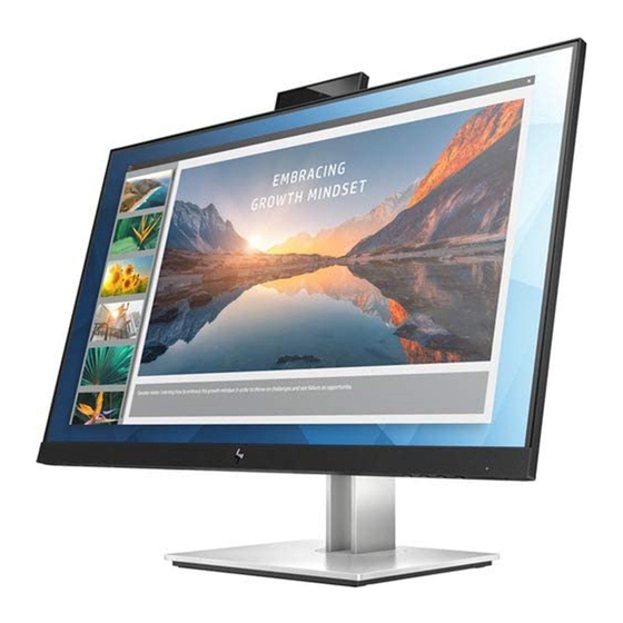
Page 9: Front Components
Front components To identify the components on the front of the monitor, use this illustration and table. Front of monitor showing location of controls Table 1-1: Front components and their descriptions Component Function Webcam LED Full High Definition (FHD) webcam Microphone On: The monitor is on. -
Page 10: Rear Components
Viewing Modes: If the OSD menu is inactive, press to activate the Viewing Modes to choose different video settings. Viewing Modes / Plus Plus: If the OSD menu is open, press to navigate forward through the OSD menu and increase adjustment levels Open the brightness chart, press to choose Brightness... - Page 11 When the monitor is on, the USB Type-C port connects a USB device, USB Type-C Thunderbolt provides data transfer, and even when the monitor is off, charges port with HP Sleep and most USB devices that have a Type-C connector, such as a mobile Charge phone, camera, activity tracker, or smart watch, and provides data transfer.
-
Page 12: Locating The Serial Number And Product Number
The SPEC label (1) and Barcode label (2) are located on the rear of the monitor. The serial number and product number are located on a Safety label. You may need these numbers when contacting HP about the monitor model. -
Page 13: Illustrated Parts Catalog
Illustrated parts catalog To identify the monitor major components, use this illustration and table. Mechanical explosion Item Description LG PANEL MID-FRAME_QWHH PI BOARD IF BOARD MAIN PCB SHIELDING IO Cover USB BOARD E274D_SIDE_BKT E274D_Webcam_ASSY REAR COVER_QWHH STAND_ARM_ASSY STAND_BASE_ASSY KEYPAD E274D_KEY_PAD LENS, V201, HF LENS, V201, HF E274D_SLIDE... - Page 14 SPK BAR COVER, JB, MT11010, HF keypad BUTTON, POWER, OSD, PC, P174 LENS, POWER, PC, P174, HF BUTTON, POWER, OSD, PC, P174 DISPLAY CHIN SCREW_Iron_I_M3*3_Machine_Black Zn SCREW, F, CROSS, T3*6, Zn SCREW, I, CROSS, M4*10, BLK-NL SCREW, PW, CROSS M4X9, Zn-CC SCREW, P, CROSS M3*6, ZN-CC SCREW, I, CROSS, M3*4 ZN-CC...
-
Page 15: How To Order Parts
How to order parts The HP authorized repair center can purchase the power board from HP. Power board Remark Description HP spare part number Manufacturer part number Common power PCBA, PI/BD, W/OSPK, LP24QJ- M84521-001 790PB1400A00H01 board of E24d A1V/E24d/HF G4&E27d G4 Capacitors and connectors are available for purchase from the following EU distributors: •... - Page 16 NOTE: HP continually improves and changes product parts. For complete and current information about supported parts for your computer, go to http://partsurfer.com, select your country or region, and then follow the on-screen instructions.
-
Page 17: Removal And Replacement Procedures
Removal and replacement procedures Adherence to these procedures and precautions is essential for proper service. Preparation for disassembly Use this information to properly prepare to disassemble and reassemble the monitor. 1) Read the “Important safety information” and “Important service information and precautions” sections in the “Getting started”... - Page 18 Remove the VESA-screws 2) Disassemble Rear-cover: Use disassembling tool to separate bucket from monitor (starting from the disassembling hole as shown). Watch out the cable of the Keypad/camera/USB. Disassemble Rear-Cover 3) Disassemble rear-cover assembly: use screwdriver to disassemble side USB and Webcam Assy...
- Page 19 Disassemble Rear-cover Assembly 4) Disassemble Side USB Chassis Assembly: Release all screws that fixed on chassis then to take out the PCB Board. Disassemble Side USB Chassis Assembly 5) Disassemble webcam Assembly: Release the screw that fixed on PCB and peel camera PMMA glass use tool/hand, then disassemble webcam Assy and take out the camera PCB...
- Page 20 Disassemble Side Webcam Assembly 6) Disassemble IO Cover: Release the screws that fixed on Panel and peel off all Foils Disassemble IO Cover 7) Disassemble chassis PCB: Release the screw that fixed on PCB and peel off Mylar/rubber Disassemble Chassis PCB...
-
Page 21: Power Board
The power board part number is 790PB1400***H01*. Before removing the power board, follow these steps: Prepare the monitor for disassembly. See Preparation for disassembly on page 13. ▲ Remove the power board: 1) The HP E24d G4 power board connector position is as follows:... - Page 22 Power Board location showing of connector CN802 Foxconn P/N: 35105Q800-39U-H 2) Locate the part number location on the board. Part number location of power board 3) Remove the backlight cable and main board.
-
Page 23: Connector Repair
Remove the backlight cable and main board Lift the connector up and away from the PCB. CN701: [image showing external connectors on the main board, such as USB, DP, etc] CN801: [image showing external connectors on the main board, such as USB, DP, etc] Connector repair This procedure includes HDMI, Display Port, headphone, USB-C, RJ45 and USB connectors. -
Page 24: Dp Connector Cn301/Cn401
Connector location showing of main board Connector Location USB(VA) P103, P104 Headphone CN102 Connector location showing of USB side board Before repairing connectors, follow these steps: Prepare the monitor for disassembly. See Preparation for disassembly on page 13. ▲ DP connector CN301/CN401 Repair the DP connector: 1) Use a hot air gun to melt the solder on the pins. -
Page 25: Hdmi Connector Cn201
Remove DP connector 2) Lift the CN301/CN401 connector from the circuit board. 3) Place the new component on the circuit board. Be sure that it matches the footprint. 4) Solder the new component. HDMI connector CN201 Repair the HDMI connector: 1) Use a hot air gun to melt the solder on the pins. -
Page 26: Usb Connector P103, P104 (Va) & P701, P702 (Ra)
Remove RJ45 connector 2) Lift the CN901 connector from the circuit board. 3) Place the new component on the circuit board. Be sure that it matches the footprint. 4) Solder the new component. USB connector P103, P104 (VA) & P701, P702 (RA) Repair the USB connector: 1) Use a hot air gun to melt the solder on the pins. -
Page 27: Function Test
1) Use e a hot air gun to heat the bottom side of PCB below the headphone connector. Remove headphone connector 2) Lift the CN102 connector from the PCB. 3) Place the new component on the circuit board. Be sure that it matches the footprint. 4) Solder the new component. - Page 28 Table 4-2: Solving common problems Problem Possible cause Solution Screen is blank or Power cord is disconnected. Connect the power cord. video is flashing. Monitor is off. Power the power button. NOTE: If pressing the Power button has no effect, press and hold the power button for 10 seconds to disable the Power button lockout...
-
Page 29: Index
USB 3.1 Super Speed port location, 7 parts, 9 USB Type-C HUB port location, 6 parts, ordering, 11 USB Type-C Thunderbolt port with HP Sleep and power board removal, 17 Charge location, 7 Power button, 6, 24 Viewing Modes / Plus, 6...