
Related Manuals for Emerson COPELAND ZO18AG


Summary of Contents for Emerson COPELAND ZO18AG
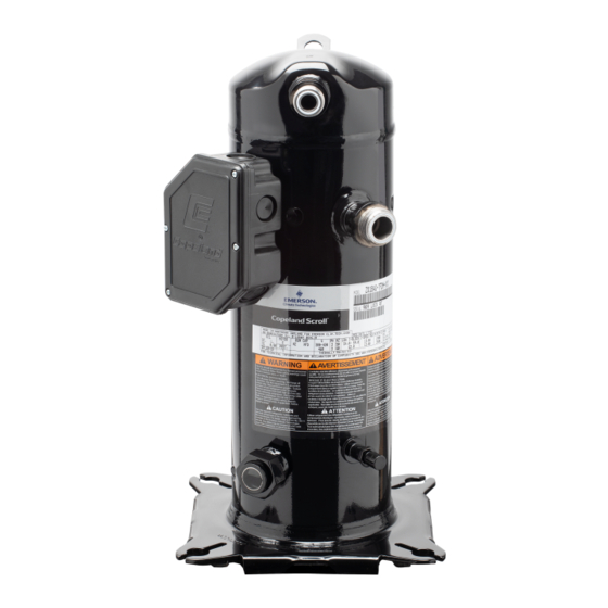
- Page 1 Application Guidelines Copeland Scroll Compressors ™ for R744 Refrigeration Applications ZO18AG to ZO46AG, ZOV18AG to ZOV38AG...
-
Page 2: Table Of Contents
About these guidelines ....................1 Safety instructions ................... 1 1.1 Icon explanation ....................... 1 1.2 Safety statements ......................1 1.3 General instructions ......................2 Product description ..................3 2.1 Compressor range ......................3 2.2 Matched pairs of compressor and drive ................3 2.3 Variable speed advantages ..................... - Page 3 4.2 Electrical wiring ......................18 4.3 Terminal box ........................19 4.4 Electro-magnetic compatibility (EMC) filter ..............20 4.5 Line reactors ........................20 4.6 Motor insulation ......................20 4.7 Motor protection ......................20 4.8 Off-cycle power consumption ..................20 4.9 High-potential testing ..................... 20 Start-up &...
- Page 4 Appendix1: Tightening torques ................32 DISCLAIMER ......................32 AGL_Ref_ST_ZO_E_Rev00...
-
Page 6: About These Guidelines
These application guidelines cover stationary applications only. For mobile applications, please contact the Application Engineering department at Emerson as other considerations may apply. Safety instructions Copeland scroll fixed- and variable-speed compressors and Emerson motor control drives are manufactured according to the latest relevant European and US safety standards. -
Page 7: General Instructions
General instructions WARNING Pressurized system! Serious personal injuries and/or system breakdown! Accidental system start before complete set-up must be avoided. Never leave the system unattended without locking it out electrically when it is on vacuum and has no refrigerant charge, when it has a holding charge of nitrogen, or when the compressor service valves are closed. -
Page 8: Product Description
25 to 100 revolutions per seconds (1/s). They are intended for use in refrigeration applications. They feature a three-phase brushless permanent magnet (BPM) motor which is controlled by an Emerson EVM/EVH motor control drive, referred to as the "EVM/EVH drive" or "drive" throughout these guidelines. -
Page 9: Variable Speed Advantages
Both situations could potentially cause compressor damage. The matched pairs of compressor and drive released by Emerson are listed in Table 2 hereunder: Max. working Compressor Drive Drive power supply... -
Page 10: Nomenclature
Rotalock IP54 / IP2X Without Table 4: BOM designation Please refer to the Emerson price list for more details. Application considerations 2.6.1 Qualified refrigerant and oil Qualified refrigerant R744 (CO Copeland standard oil Zerol RFL68-EP (PAG) Servicing oil... -
Page 11: Application Limits
For application envelopes and technical data, please refer to Copeland Select software available at www.climate.emerson.com/en-gb. Figure 4: Envelope of the ZO*AG compressors Figure 5: Envelope of the ZOV*AG compressors NOTE: For matched pairs with smaller drives, please check the application envelopes in Copeland Select software at www.climate.emerson.com/en-gb. AGL_Ref_ST_ZO_E_Rev00... - Page 12 Figure 5 – also see speed limits animation in Select software available at www.climate.emerson.com/en-gb. ▪ Fast speed changes can cause instable control, eg, on the superheat control. Per Emerson experience speed changes should be not higher than approximately 200 rpm/s depending on the system reaction.
-
Page 13: Ped Category, Maximum Allowable Pressures Ps And Internal Free Volume
2.6.3 PED category, maximum allowable pressures PS and internal free volume The ZO(V)*AG compressor models covered in these guidelines are PED Class 1, according to the Pressure Equipment Directive PED 2014/68/EU. The pressure PS is the maximum allowable pressure at the low- and high-pressure sides of the compressor. -
Page 14: Design Features
2.6.5 Design features The variable-speed scroll ZOV*AG has a number of design features that improve efficiency and reliability. An HVE valve is part of ZOV*AG models for higher performance at high pressure ratio. This valve prevents reverse rotation during shutdown; however, some shutdown sound may occur. All ZOV*AG compressors are equipped with a positive displacement oil pump to ensure an adequate supply of oil to the bearing system throughout the operating speed range of 1500 to 6000 rpm. -
Page 15: Dimensions
Dimensions Figure 9: External dimensions of the ZO*AG Compressor ZO18AG to 415.8 mm 390.2 mm 209.9 mm 67.4 mm 83.2 mm 285.8 mm ZO46AG Table 8: Dimensions of the ZO*AG Figure 10: External dimensions of the ZOV*AG Compressor ZOV18AG to 385.8 mm 360.1 mm 179.9 mm... -
Page 16: Installation
Installation WARNING High pressure! Injury to skin and eyes possible! Be careful when opening connections on a pressurized item. Compressor and drive handling WARNING Static electricity! Personal injuries! Personnel handling the drives in a manufacturing plant environment should guard against static electricity by using the appropriate equipment, eg, antistatic wrist straps and mats. -
Page 17: Compressor Mounting Parts
Rotalock shut-off valves are available for the suction as well as discharge sides. Please refer to Appendix 1 for proper tightening torques. NOTE: More information about adaptors and shut-off valves can be found in the Emerson spare parts software, available at www.climate.emerson.com/en-gb/tools-resources. -
Page 18: Pressure Safety Controls
The low-pressure control must be installed correctly into the suction line, which means that no service valve is allowed between the compressor and the pressure protection. The minimum cut-out setting shall be determined according to the refrigerant and the allowed operation envelope – see Select software at www.climate.emerson.com/en-gb. Crankcase heater CAUTION... -
Page 19: Discharge Gas Temperature Protection
ZOV18AG to ZOV38AG Table 10: Crankcase heater position NOTE: Please refer to the Spare Parts list available at www.climate.emerson.com/en-gb/tools- resources to select the correct crankcase heater model. Caution: Crankcase heaters must be properly grounded! For installation, the manufacturer/installer shall follow the recommendations mentioned below. -
Page 20: Excessive Discharge Gas Temperatures
Figure 18: Sensor installation NOTE: For complete mounting recommendations please refer to Assembly Instructions. C30.11 "NTC Mounting Recommendations". NOTE: When using an Emerson qualified drive, please refer to the drive user manual to see how to connect it. AGL_Ref_ST_ZO_E_Rev00... -
Page 21: Filter Screens
The sensor has to be used as a protection device, when the temperature of the discharge line exceeds the limit – see Table 11. Compressor Discharge line model temperature limit ZO(V)*AG 135 °C Table 11: Maximum allowed discharge line temperature Filter screens CAUTION Screen blocking! Compressor breakdown! Use screens with at least... -
Page 22: Active Oil Management
OM4 TraxOil components for low pressure oil management. Typically, an additional oil reservoir is needed in this case. If the pressure in the oil separator/reservoir is higher than 60 bar Emerson recommends using the OM5 TraxOil components. The OM5 is suitable for both high- and low-pressure oil management systems. -
Page 23: Electrical Connection
Before connecting the compressor, ensure the supply voltage, the phases and the frequency match the nameplate data. For safety reasons, Emerson recommends that the electrical installation be executed in compliance with standard EN 60335-1 and/or other standards and regulations of application. The wiring must conform to local regulations and codes of practice. -
Page 24: Terminal Box
Fusite pins which might lead to refrigerant leaks. Cable glands have an influence on the protection class of the terminal box. Emerson strongly recommends using appropriate cable glands according to EN 50262 in order to reach the rated protection class. -
Page 25: Electro-Magnetic Compatibility (Emc) Filter
Electro-magnetic compatibility (EMC) filter The Emerson qualified EVM/EVH drive can fulfill RSCE120. The user needs to contact the public grid supplier for permission. For applications and job sites that are sensitive to electro-magnetic interference (EMI), an EMC filter for the EVM/EVH drive is available as an accessory. -
Page 26: Start-Up & Operation
DO NOT USE other industrial gases. 5.1.1 Compressor strength-pressure test The compressor has been strength-tested in the Emerson factory. Therefore, it is not necessary for the system manufacturer/installer to strength-test the compressor again. Scroll compressors are divided into two pressure zones. The compressor high-side and low-side maximum allowable pressures PS have to be respected at all times. -
Page 27: System Evacuation
All compressors get a factory holding charge of dry air (about 1 to 2.5 bar, relative pressure). An intact holding charge serves as a proof of quality against penetrating moisture. When removing plugs from the compressor, the plugs may pop out due to pressure and oil can spurt. Any later modification to compressor connections can have an impact on the compressor tightness. -
Page 28: Run-In Time
Run-in time Scroll compressors exhibit a slight decrease in input power during the initial running period. Published performance ratings are based on calorimeter testing which is carried out after run-in. Therefore, users should be aware that before the performance specified by EN 12900 is achieved the compressor needs to be run in. -
Page 29: Deep Vacuum Operation
5.14 Minimum run time Emerson recommends a maximum of 10 starts per hour. There is no minimum off time because scroll compressors start unloaded, even if the system has unbalanced pressures. The most critical consideration is the minimum run time required to return oil to the compressor after start-up. -
Page 30: Maintenance & Repair
Maintenance & repair WARNING Conductor cables! Electrical shock! Follow the lockout/tag out procedure and the national regulations before carrying out any maintenance or service work on the system. Use compressor with grounded system only. Screwed electrical connections must be used in all applications. Refer to original equipment wiring diagrams. Electrical connections must be made by qualified electrical personnel. -
Page 31: Replacing A Compressor
Since PAG holds moisture more readily than mineral oil it is more difficult to remove it through the use of vacuum. The compressors supplied by Emerson contain oil with low moisture content, which may rise during the system assembling process. Therefore, it is recommended that a properly sized filter-drier be installed in all PAG systems. -
Page 32: Oil Additives
Oil additives Although Emerson cannot comment on any specific product, from our own testing and past experience, we do not recommend the use of any additives to reduce compressor bearing losses or for any other purpose. -
Page 33: Troubleshooting
Troubleshooting WARNING Electrical cables! Electrical shock! Before attempting any electrical troubleshooting, make sure all grounds are connected and secure and there is ground continuity throughout the compressor system. Also ensure the compressor system is correctly grounded to the power supply. If you are not a qualified service person familiar with electrical troubleshooting techniques, DO NOT PROCEED until a qualified service person is available. - Page 34 Condition Cause Corrective action Compressor Check if there is continuity on the compressor external protector. If the motor protector compressor is warm, it may require considerable time to cool down. open Defective Check if the pressure control or thermostat works properly or if the system control controls are open.
- Page 35 Cause Corrective action Excessive Too high Make sure the compressor operates within the acceptable superheat discharge compressor range published by Emerson. temperature superheat Excessive cooling / heating Check the load design. Make sure that proper insulation is applied. load or Correct as necessary.
-
Page 36: Dismantling & Disposal
The latest version of Copeland Select software with performance data and technical data is available from the webpage www.climate.emerson.com/en-gb. Spare parts and accessories: An online version of the Emerson spare parts and accessories software is available from the webpage www.climate.emerson.com/en-gb/tools-resources. AGL_Ref_ST_ZO_E_Rev00... - Page 37 3. Emerson does not assume responsibility for the selection, use or maintenance of any product. Responsibility for proper selection, use and maintenance of any Emerson product remains solely with the purchaser or end user.
- Page 38 The Emerson logo is a trademark and service mark of Emerson Electric Co. Emerson Climate Technologies Inc. is a subsidiary of Emerson Electric Co. Copeland is a registered trademark and Copeland Scroll is a trademark of Emerson Climate Technologies Inc.. All other trademarks are property of their respective owners.