Table of Contents
Advertisement
Quick Links
Advertisement
Table of Contents

Related Manuals for Fellowes ESI Evolve


Summary of Contents for Fellowes ESI Evolve
- Page 1 Evolve Monitor arm series Universal assembly and operation instructions...
- Page 2 Evolve Universal assembly guide Caution • The monitors should not be positioned behind the mounting location of the base. • If the monitor arm is installed ona desk or table with open space behind the arms, it is recommended to install the 180º lockout screws. •...
-
Page 3: Table Of Contents
Evolve Table of contents Basic components Basic components ..............4 Configurations F - Fixed / FS - Fixed Slider EVOLVE1-F (SINGLE) ..........6 EVOLVE1-FS (SINGLE) ..........6 EVOLVE2-F (DUAL) ..........6 EVOLVE2-FS (DUAL) ..........6 M - Motion / MS - Motion Slider EVOLVE1-M (SINGLE) ..........7 EVOLVE1-MS (SINGLE) ..........7 EVOLVE2-M (DUAL) ..........7... -
Page 4: Basic Components
Evolve Basic components Pole mounts Desk clamp Grommet mount Motion arm Profile view Angle view Fixed arm Profile view Angle view... - Page 5 Evolve Basic components Arm stem 1. Rotation tension adjustment 2. Secure arms 3. 180º lock-out Profile view Angle view VESA mount Slider mount Display mount Display mount Standard bushing Small Reducer bushing bushing Preinstalled on stem arm For VESA & slider mounts For VESA &...
-
Page 6: F - Fixed / Fs - Fixed Slider Evolve1-F (Single)
Evolve1-F Evolve1-FS Evolve2-F Evolve2-FS More complete instructions for part assembly can be found on the page numbers listed below. This may include, but is not limited to, screws, adjustment knobs, bushings and surface protection. Pole mount (PG. 10) Secure pole mount to worksurface. -
Page 7: M - Motion / Ms - Motion Slider Evolve1-M (Single)
Evolve1-M Evolve1-MS Evolve2-M Evolve2-MS More complete instructions for part assembly can be found on the page numbers listed below. This may include, but is not limited to, screws, adjustment knobs, bushings and surface protection. Pole mount (PG. 10) Secure pole mount to worksurface. -
Page 8: Ff - Fixed Fixed / Ffs - Fixed Fixed Slider Evolve1-Ff (Single)
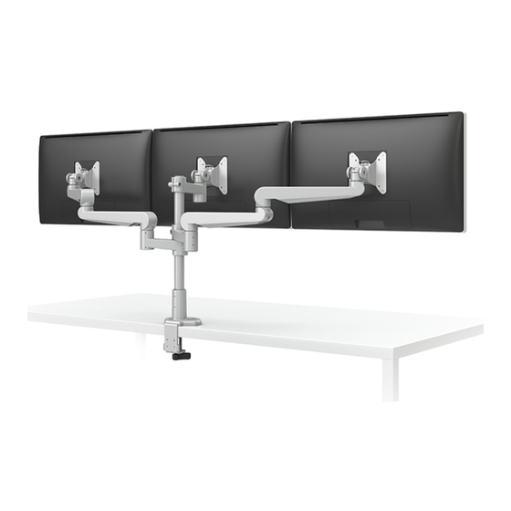
Evolve1-FF Evolve2-FF Evolve3-FF Evolve1-FFS Evolve2-FFS Evolve3-FFS More complete instructions for part assembly can be found on the page numbers listed below. This may include, but is not limited to, screws, adjustment knobs, bushings and surface protection. Pole mount (PG. 10) Secure pole mount to worksurface. -
Page 9: Fm - Fixed Motion / Fms - Fixed Motion Slider Evolve1-Fm (Single)
Evolve1-FM Evolve2-FM Evolve3-FM Evolve1-FMS Evolve2-FMS Evolve3-FMS More complete instructions for part assembly can be found on the page numbers listed below. This may include, but is not limited to, screws, adjustment knobs, bushings and surface protection. Pole mount (PG. 10) Secure pole mount to worksurface. -
Page 10: Pole Mount
Step #1 Pole mount You will receive parts to accommodate either the desk clamp mount or the grommet mount. Option 1 Option 2 Desk clamp (PG.11) Grommet mount (PG. 12) Secure pre-assembled desk clamp mount Convert the desk clamp mount to a to work surface. - Page 11 Desk clamp assembly For worksurface 0.66”- 2.2” Optional adjustment Step 1 for thicker worksurfaces Adhere the adhesive pad 1.38”-2.99” underneath the base to protect the worksurface. Step 2 (optional) Adjust clamp positioning to accommodate a thicker worksurface. Step 3 Slide onto worksurface to desired position.
- Page 12 Grommet mount assembly For worksurface up to 1.5” Step 1 Step 2 Remove the 3 screws with the Insert the large screw to the 4mm Allen key. grommet plate and reattach the 3 screws with the 4mm Allen key. 4mm Allen key (Included) Step 3 Step 4 Adhere the adhesive pad Complete the grommet mount...
-
Page 13: Arm Stems
Step #2 Stem arm Each diagram/step may not applicable to your product configuration. Single display configuration Step 1 Slide stem arm over pole and secure with the 5mm Allen key. 5 mm Allen key (Included) Dual display configuration Step 2 Reverse the second stem arm over pole as shown and secure NOTE with the 5mm Allen key. -
Page 14: Attach Arms
Step #3 Attach arms Each diagram/step may not applicable to your product configuration. Insert a motion arm or fixed arm into a stem arm. motion arm Step 1 Insert motion arm or fixed arm to stem arm. Step 2 Secure the screw using the 2mm Allen key. - Page 15 Step #3 Attach arms Insert a motion arm or fixed arm into a fixed arm motion arm Step 1 Insert motion arm or fixed arm to fixed arm. Step 2 Secure the screw using the 2mm Allen key. fixed arm 1. Rotation tension adjustment 2.
-
Page 16: Display Mounts
Step #4 Display mounts Insert VESA to a stem arm. Step 1 Step 2 Step 3 Attach reducer bushing onto Insert VESA mount to arm stem. Secure the screw using the VESA mount. For detailed 2mm Allen key. instructions on how to attach the reducer bushing please reference the slider mount instructions. - Page 17 Step #4 Display mounts Insert VESA or slider to a motion or fixed arm. reducer bushing small bushing Fixed arm Motion arm Step 1 Step 2 Step 3 Attach bushing Insert slider mount to Secure the screw using the onto VESA or slider. motion arm or fixed arm.
-
Page 18: Attach Display
Step #5 Attach display VESA plate is pre-drilled to accommodate varying monitor standards. Step 1 100mm Pull the tab to release the quick release VESA plate. Two options of pre-drilled holes Step 2 to accommodate varying monitor Pull the quick release VESA plate standards upward to detach. -
Page 19: Adjust Tension
Step #6 Adjust tension Adjusting the tension on your motion arm allows for smooth adjustments. Tension adjustment supports monitors weighing 6.6 - 17.6 lbs. Adjust motion arm tension Step 1 Use the 5mm Allen key to adjust the tension to correspond to the weight of the monitor. -
Page 20: Lock Features
Step #7 Lock features Optional features 180° lock monitor arm The 180º lock-out feature allows 90º rotation towards the user, but prevents 90º rotation away from the user. Step 1 Fasten the screw with the 2mm Allen key on the arm stem and then move the Allen key backward one circle motion to limit arm rotation. - Page 21 Step #7 Lock features If desired, the slider mount can be Lock slider plate secured to prevent the slider function. This will lock a monitor in position. lock screw lock screw Prevent VESA mount quick release Step 1 To prevent the quick release function, insert the screw to the back of the VESA mount.
-
Page 22: Cable Management
Step #8 Cable management Optional features Step 1 Slide cable tray outward to detach from fixed arm. Step 2 Route cables through fixed arm tray and reattach. pole clips Step 1 Step 1 Detach pole clip and Squeeze clip then pull to route cables. -
Page 23: Allen Key Storage
Other Additional features Allen key storage Once assembly is complete, place the Allen keys in the slots located on the back side of the VESA and slider mounts. Insert the two smaller Allen keys simultaneously. - Page 24 ESI’s sole obligation under this warranty or any implied warranty, and the purchaser’s sole remedy, is limited to the repair or replacement, at ESI’s option, of the product or any defective part. Costs (such as installation, labor fees or express shipping) incurred due to replacement of products are not covered under warranty. IN NO EVENT SHALL FELLOWES, ITS AFFILIATES, SUBSIDIARIES, RELATED ENTITIES OR THEIR RESPECTIVE OFFICERS, DIRECTORS, OR EMPLOYEES, BE LIABLE FOR INCIDENTAL, CONSEQUENTIAL, PUNITIVE, EXEMPLARY, OR SPECIAL DAMAGES.