Advertisement
Quick Links
certified
EN norms
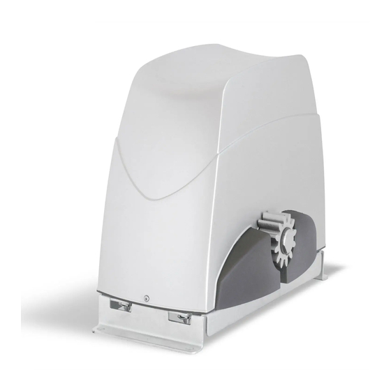
S L I D E
I n s t a l l a t i o n i n s t r u c t i o n s
S l i d i n g g a t e o p e n e r s
m o d e l s :
S L I D E 4 4 6
( M o t o r 1 2 V , e l e c t r o n i c b o a r d C T H 4 6 ) = S L I D E 6 4 6 = S L I D E 6 0 0
S L I D E 8 4 3 / 2 4 V
( M o t o r 2 4 V , e l e c t r o n i c b o a r d C T H 4 3 V / 2 4 V )
S L I D E 1 0 4 3 / 2 4 V
( M o t o r 2 4 V , e l e c t r o n i c b o a r d C T H 4 3 V / 2 4 V )
S L I D E 4 4 6
S O L A R
S O L A R
( M o t o r 1 2 V , e l e c t r o n i c b o a r d C T H 4 6 )
S L I D E 7 4 3 / 1 2 V
S O L A R
S O L A R
( M o t o r 1 2 V , e l e c t r o n i c b o a r d C T H 4 3 V / 1 2 V )
https://ducatihome.it
m a n u a l
R E V 0 0 0 - 0 9 - 0 7 - 1 9 E S
Advertisement

Related Manuals for Ducati SLIDE 446


Summary of Contents for Ducati SLIDE 446
- Page 1 certified EN norms S L I D E m a n u a l R E V 0 0 0 - 0 9 - 0 7 - 1 9 E S I n s t a l l a t i o n i n s t r u c t i o n s S l i d i n g g a t e o p e n e r s m o d e l s : S L I D E 4 4 6...
- Page 2 * = before August 2020 ** = from August 2020 Attention: from January 2021 the supplied frame could be the RACK8622 model with steel core and fixing slots DUCATI LIMITS OF USE AND ENGINE TECHNICAL FEATURES KIT SLIDE 446 e KIT SOLAR SLIDE KIT SLIDE KIT SLIDE 1043/24V...
- Page 3 Stand-by power consumption 0,007A Protection fuse Automatic Transformer protection fuse 0,8A T (1,2A T) DUCATI 433.92 MHz 2-channels radio receiver with variable code Integrated coding (Ducati rolling code) Memory capacity of the radio receiver 20 channels Self-learning of remote controls √...
- Page 4 DUCATI INDEX Scheme Page See also the drawings The contents of the kit follow the model / limits of use / technical characteristics Mechanical installation drawings 5-10 CTH46 electronic board diagram CTH43 electronic board diagram 12-13 Preliminary opinions and safety advice...
- Page 5 DUCATI INSTALLATION DIAGRAM AND MOTOR DIMENSIONS 19 cm 34 cm South orientation orientación sur Orientation Guide Wall Wall Mechanical limit Fixing plate (optional) Binary Rail Butée mécanique switch de votre portail Rack Remote controls A – Crémaillère M4 F – Télécommandes à 2 ou 4 canaux.
- Page 6 DUCATI DRAWING FOR QUICK INSTALLATION STANDARD right opening Blue BLUE Blue Left opening BLUE PLAK 8700 fixing plate (optional) Direct fixing to the Attention, adjust the position of the motor on the plate to the ground maximum height. In the future it can therefore be adapted to the...
- Page 7 DUCATI DRAWING FOR QUICK INSTALLATION To block To unlock 1-2mm max. sí Fix the rack piece by piece passing the same di- portale stance from the gear, the rack must always be at the same distance from the gear without major friction points.
- Page 8 DUCATI DRAWING FOR QUICK INSTALLATION M = Magnet R = Magnetic detector MAGNO 003 Mechanical limit switch M = Magnet R = Magnetic detector Mechanical limit switch MAGNO 001 Temporary adjustment of the limit switch magnets Closed gate limit switch...
- Page 9 DUCATI DRAWING FOR QUICK INSTALLATION 9.A.3 black 9.A.4 black yellow 9.A.1 9.A.2 CTH46 CTH46 CTH 43V/24 CTH43 CTH46 CTH43V (24V) CTH43 (12V) CTH43V (12V) Boards in 12V ver- Boards in 24V ver- sion = powered by sion = powered by...
- Page 10 DUCATI DRAWING FOR QUICK INSTALLATION 10.1 10.2 10.3 10.4 (LRN) CLOSED Closed gate Time Power Press the button on Press and release button P1 (remote the remote control to control self-learning) memorize it 11.1 11.2 11.3 to block To unlock Manually open the gate halfway 12.1...
- Page 11 DUCATI CTH46 QUICK INSTALLATION: Electronic board diagram (see page 20) Electronic board CTH46 (12V) Photovoltaic solar Connections: panel antenna cable. antenna ground. 12V min.10W START COM common. contact for start-up (NO) START contact for wired command of the complete opening cycle (NO contact, normally open).
- Page 12 DUCATI CTH43V Scheme of electronic board Radio receiver Electronic board model CTH43V with 12V power supply: external Ref.RX43 230(110V) Backup battery connection by CMBAT charger (optional) (optional) CTH43/12V CMBAT Transformer max100 sec. sec. Battery12V BLACK Red = 24 V min.7A...
- Page 13 DUCATI CTH43V/12V Electronic board diagram powered by solar panel CMBAT DISPLAY Time Power CMBAT (LRN) (TRAVEL) module connector battery solar panel 12V by12V min 10W Time Power + Positive power supply - Negative power supply 9 10 11 12 Setting the starting point of deceleration...
- Page 14 DUCATI CTH43V/24V Electronic board diagram powered by solar panel max100 sec. CMBAT DISPLAY CMBAT DISPLAY Time Power (LRN) (TRAVEL) CMBAT Battery by Solar panel Solar panel Battery by 12V min.7A 12V min 10W module 12V min 10W 12V min.7A connector...
- Page 15 CTH43 jumper only when connecting an emergency stop switch. Electronic board WARNING: Be careful when connecting the optional battery charger, Modul Ref. Attention 3 versions of this existing board: CMBAT. respect the polarity of the connections: CMBAT connector "+ to board" = + positive connector on the CTH43 / CTH43V board. a) CTH43N version: 12V without SOFT-STOP (double speed with slowdown).
- Page 16 DUCATI WARNINGS AND SAFETY CHECKS 1) PRELIMINARY CHECKS BEFORE INSTALLATION: B) DURING INSTALLATION: Personal safety recommendation: - Check that the gate is professionally installed and complies with the safety - Do not use accessories or clothing that could become entangled in the drive system...
- Page 17 DUCATI WARNINGS AND SAFETY CHECKS AFTER INSTALLATION: Maintenance: - Check the correct execution in each phase and check that the gate slides correctly - Perform regular maintenance of the structure to ensure maximum safety. in manual operation, without any point of friction.
- Page 18 DUCATI INSTALLATION motor cables, taking care not to damage the support of the brush holder blades. WARNING: The gate must be equipped with mechanical stops that prevent the drawing 3.3. gate from derailing, causing a risk of serious danger to the life of people or things.
- Page 19 DUCATI INSTALLATION WARNING: Once finished, manually move the gate and check that it slides smoothly 6) FIXING FROM THE RACK TO THE GATE along its length without showing any friction points. If not, correct the attachment of (See the drawings in section 6).
- Page 20 Attention: the remote controls supplied with the kit are normally already memorized The motorization model SLIDE 446 / SLIDE 446 SOLAR is supplied with the electro- with the board for their motorization (remote control button at the top left, memorized nic board model CTH46 specially designed for powering by solar panel with energy by the manufacturer for the total maneuver cycle).
- Page 21 DUCATI INSTALLATION How to memorize a remote control: 11) FINAL POSITION OF THE LIMIT SWITCH MAGNETS Attention, check that: - The gate must be closed on the limit switch magnet. Check that the yellow LED on To identify the final fixing position of the limit switches, open the opening and closing the electronic board is on.
- Page 22 DUCATI ELECTRICAL CONNECTIONS / BOARD SETTINGS CTH46 12.1) ELECTRONIC BOARD CTH46 (see page 11) WARNING: Three feeding methods: Terminal blocks 7/8 are connected by an electric bridge to keep the photocell con- a) by switch 230V (110V or on request).
- Page 23 DUCATI SETTINGS OF THE CTH46 BOARD code. Procedure completed. ENGINE POWER ADJUSTMENT: The "POWER" potentiometer / trimmer allows you to adjust the motor power and the b) Memorize a button to command a partial maneuver cycle for pedestrian ac- cess sensitivity to detect a possible obstacle during the run.
- Page 24 DUCATI ELECTRICAL CONNECTIONS / BOARD SETTINGS CTH43/CTH43V CTH43 battery and possibly a solar panel. ELECTRONIC BOARD Be careful not to connect a battery directly to the +/- connectors of the CTH43 board! Attention there are 3 versions of this board: a) CTH43N 12V version.
- Page 25 DUCATI SETTINGS OF THE CTH43/CTH43V BOARD allow a flexible stop. POTENTIOMETERS: The card is supplied with slow start 7 seconds after the start of the race. The gate will T1 (TIME) = This potentiometer allows you to choose between "step by step" ope- rating mode (impulse to open and impulse to close the gate) or operating mode have traveled about 1.5 m.
- Page 26 Each button on the transmitter is factory programmed with a unique radio code that corresponds to a transmission channel. Each button can be used to control a different function or a different DUCATI engine. With the addition of an external DUCATI Rolling Code radio receiver (Ref. RIXY 6040 or RIXY 6043 with display), battery: battery: you can also control other instruments, using the same Ducati remote control.
- Page 27 DUCATI R A D I O K E Y P A D ROLLING CODE DUCATI SW6500/TASTY Radio keypad SW6500/TASTY 6500 powered by 2 lithium batteries CR2450 3V. The keyboard is used to operate the radio frequency automation. The transmission of the radio signal is protected by a customized 4-digit code.
- Page 28 DUCATI K E Y S E L E C T O R It is used to command the opening or closing of the gate. The key selector must be connected to the "START" or "PEDESTRIAN START" contact of the motorization electronic board.
- Page 29 DUCATI FLASHING Bulb 12V max 10W the flashing light is important to indicate a moving engine Installation: 1- Open the flashing light. 2- Unscrew the 2 screws inside. 3- Remove the lower part. 4- Define the position of the flashing light and then locate the punch positions.
- Page 30 DUCATI Photocells LASER 100/LASER 100B/LASER 200 LASER 100...universal photocell set. 12V / 24V ac / dc power supply with NC contact (normally closed) + NO contact (normally Series connection of several pairs of open). photocells LASER 100/B...universal photocell set. 12V / 24V ac / dc power supply with NC (normally closed) or NO (normally open) contact).
- Page 31 DUCATI Guarantee Warranty conditions and after sales service MANUFACTURER'S LIMITED WARRANTY CONDITIONS 1) The warranty is valid only if it is attributable to an original defect of the product. 2) Warranty period: 24 months from the date of sale. 3) If, during the period of this limited warranty, the product appears to contain a defect covered by this warranty, the customer must follow the after-sales service procedure.
- Page 32 Our service is at your disposal 7 days a week, 24 hours a day, to guide you in the selection, installation and use of our products. contact us and visit our websites: www.ducatihome.it and www.apritu.it DUCATI HOME AUTOMATION Automazione Cancelli...
- Page 33 Register in: www.ducatihome.it SUPPORT 7/24h VIDEO -NOTICES PROMO ADVICE INDEPENDENT PIECES...
- Page 34 REGISTER ON OUR SITE www.ducatihome.it TO BENEFIT FROM MANY OFFERS AND PROMOTIONS! ALSO ACCESS OUR VIDEO-NOTICES! Ducati Home Automation Automazione cancelli via Cassani 43036 Fidenza (PR) ITALY Phone +39-0524-527967 Phone +39-0524-591085 d u c a t i h o m e . i t Phone 0039-335-1022019 info@ducatihome.it...