Advertisement
Advertisement
Table of Contents

Related Manuals for Cerwin-Vega CV-900


Summary of Contents for Cerwin-Vega CV-900
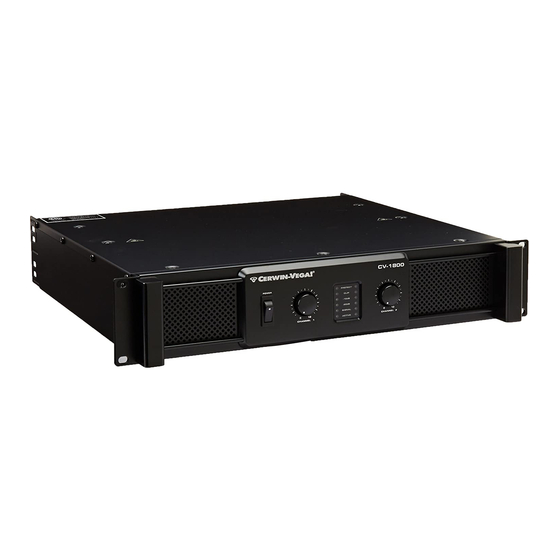
- Page 1 CV-900 / CV-1800 / CV-2800 HEAVY DUTY PROFESSIONAL AMPLIFIERS USER MANUAL...
-
Page 2: Important Safety Instructions
IMPORTANT SAFETY INSTRUCTIONS 10. WARNING: The mains plug or amplifier power inlet is used as a disconnet 1. Read Instructions – All the safety and operating instructions should be read before device, the disconnect device shall remain readily operable. Protect the power this product is operated. -
Page 3: Unpacking And Installation
• Cerwin-vega amplifiers deliver the following power ratings. • CV-900 - 2 x 210 Watts at 8 ohm, 2 x 320 Watts at 4 ohm and 2 x 420 Watts at 2 ohm • CV-1800 - 2 x 400 Watts at 8 ohm, 2 x 600 Watts at 4 ohm and 2 x 900 Watts at 2 ohm •... -
Page 4: Front Panel Controls
When the channel goes into protect mode all output for that The CV-Series amplifiers are cooled by two rear-mounted fans (ex- cept for CV-900 which is cooled by a single rear mounted fan). channel will be muted. The protect LED's light when overheating or Cool air flows through the front fan filters, reducing the other severe problems occur. -
Page 5: Rear Panel Controls
REAR PANEL CONTROLS 7. 5-way Binding Post 1. Fan This is a variable speed cooling fan. Cool air enters the amplifier Connect each channel of the unit to your speakers. Binding posts through the fan filters located on the front of the amplifier. Be sure ®... - Page 6 PROTECTION Every model in the CV-Series incorporates protection features. The front panel Protection LED indicates the activity of the speaker connection relay circuitry in each channel. When the protection LED turns on, this circuitry is active, and all connected speakers are muted. Initial power-up : For approximately five seconds after initial Subsonic Frequency Protection : The built-in High Pass Filter power-up, the protection circuitry is activated and the speaker out-...
- Page 7 SETUP CONNECTIONS Stereo Mode Mode Select (5-Way Ouptut Binding Posts) Stereo Mode In stereo mode, both channels operate independently with individ- ual input gain controls. Signal at channel 1’s input produces output at channel 1, while signal at channel 2’s input produces output at channel 2’s output.
- Page 8 CONNECTIONS Stereo Mode SPK+ to PIN 1+ SPK+ to PIN 1+ SPK- to PIN 1- SPK- to PIN 1- SPK+ to PIN 1+ SPK+ to PIN 2+ SPK- to PIN 1- SPK- to PIN 2- Parallel Mode SPK+ to PIN 1+ SPK+ to PIN 1+ SPK- to PIN 1- SPK- to PIN 1-...
- Page 9 WIRING These are several ways to interface to the amplifier to support a variety of applications. Unbalanced 1/4” Connector ® Speakon Connector Balanced TRS 1/4” Connector XLR Balanced Wiring Guide...
-
Page 10: Specifications
SPECIFICATIONS... - Page 11 The CV Series of amplifiers are designed to work with many different speakers on the market. They have been paired with the following Cerwin-Vega speakers. The following compatibility matrix can be used as a reference. (See: www.cerwin-veg com for product specs.)
-
Page 12: Features And Benefits
C C V V - - S S E E R R I I E E S S A A m m p p l l i i f f i i e e r r s s The Cerwin-Vega! CV-Series high performance professional power amplifiers are rugged, 2U rackmountable workhorses with the muscle to accommodate the most demanding audio challenge.