Table of Contents
Advertisement
Available languages
Available languages
ATTACH YOUR RECEIPT HERE
Serial Number _____________________________ Purchase Date ______________________
Questions, problems, missing parts? Before returning to your retailer, call our customer
service department at 1-877-447-4768, 8:30 a.m. – 4:30 p.m., CST, Monday – Friday
or e-mail us at customerservice@ghpgroupinc.com.
70-10-130
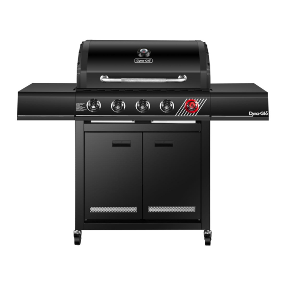
5-BURNER LP GAS GRILL
WITH SEAR STATION
Model #DGH483CRP/DGH483CRP-D
1
Français p. 33
XX
Français p.
Español p. 65
XX
Español p.
Rev. 12/06/2018
Advertisement
Table of Contents

Related Manuals for Dyna-Glo DGH483CRP


Summary of Contents for Dyna-Glo DGH483CRP
- Page 1 5-BURNER LP GAS GRILL WITH SEAR STATION Model #DGH483CRP/DGH483CRP-D Français p. 33 Français p. Español p. 65 Español p. ATTACH YOUR RECEIPT HERE Serial Number _____________________________ Purchase Date ______________________ Questions, problems, missing parts? Before returning to your retailer, call our customer service department at 1-877-447-4768, 8:30 a.m.
- Page 2 TABLE OF CONTENTS Safety Information ........................3 Package Contents ........................5 Hardware Contents ........................6 Preparation ..........................6 Assembly Instructions ........................ 7 Operation Instructions ......................... 19 Care and Maintenance ......................... 24 Troubleshooting ........................... 27 Warranty ............................29 Replacement Parts List ......................30 Assembler/Installer: This manual contains important information necessary for the proper assembly and safe use of this appliance.
- Page 3 SAFETY INFORMATION Please read and understand this entire manual before attempting to assemble, operate or install the product. If you have any questions regarding the product, please call customer service at: 1-877-447-4768, 8:30 a.m. – 4:30 p.m., CST, Monday – Friday. DANGER •...
- Page 4 SAFETY INFORMATION WARNING • Do not place the grill under overhead combustible construction or awnings. Minimum clearance from sides and 36in back of unit to combustible construction, 36in 914.4mm 36 inches (914.4mm) from sides and back. 914.4mm NOTE: The installation must conform with local codes or, in the absence of local codes, with either the National Fuel Gas Code, ANSI Z223.1/NFPA 54, Natural...
- Page 5 PACKAGE CONTENTS PART DESCRIPTION QUANTITY PART DESCRIPTION QUANTITY Temperature Gauge Right Side Table Facing Panel Temperature Gauge Bezel Cart Left Side Panel Assembly Lid Handle Assembly Cart Rear Panel Grill Body Cylinder Exclusion Main Burner Knob Cart Right Side Panel Assembly Sear Burner Knob Upper Front Door Brace Grease Pan...
- Page 6 HARDWARE CONTENTS (shown actual size) M6 Plain M6x16 M4x12 Door Upper Washer Screw Screw Hinge Qty. 39 Qty. 8 Qty. 2 Qty. 2 M6 Spring M6 Wing Washer Wrench Qty. 2 Qty. 2 Qty. 1 PREPARATION Before beginning assembly of product, make sure all parts are present. Compare parts with package contents list on previous page and hardware contents above.
- Page 7 ASSEMBLY INSTRUCTIONS Attach Lower front cart frame (Z) to Bottom shelf (W) with three M6x16 screws (AA). Hardware Used M6x16 Screw Attach Cart left side panel assembly (R) and Cart right side panel assembly (U) to Lower front cart frame (Z) and Bottom shelf (W) with six M6x16 screws (AA).
- Page 8 ASSEMBLY INSTRUCTIONS Attach 2 Locking swivel casters (X) and 2 Non- locking swivel casters (Y) to Cart left side panel assembly (R) and Cart right side panel assembly (U) with M10 wrench (GG). Hardware Used M10 Wrench Attach Cart rear panel (S) to Cart left side panel assembly (R) and Cart right side panel assembly (U) with four M6x16 screws (AA).
- Page 9 ASSEMBLY INSTRUCTIONS Attach Upper front door brace (V) to Cart left side panel assembly (R) and Cart right side panel assembly (U) with four M6x16 screws (AA). Pre-assemble two M4x12 Screws (BB) onto the Cart right side panel assembly (U) and do not tighten them.
- Page 10 ASSEMBLY INSTRUCTIONS Insert the bottom axis in the Left door assembly (A1) into the hole on the Lower front cart frame (Z), and insert the Door upper hinge (CC) into the holes of the upper front door brace (V) and the hole in the upper Left door assembly (A1) as shown.
- Page 11 ASSEMBLY INSTRUCTIONS First, remove pre-assembled Wing nut and Plain washer from Temperature gauge (A), then attach Temperature gauge (A) and the temp gauge bezel (B) to Grill body (D).Secure Temperature gauge (A) with Wing nut and Plain washer removed earlier in this step. Assemble the 4 main burner knobs (E) and 1 sear burner knob (F).
- Page 12 ASSEMBLY INSTRUCTIONS Carefully place the Grill body (D) onto Cart left side panel assembly (R) and Cart right side panel assembly (U). Adjust the Grill body (D) so that the holes in the Grill body (D) are aligned with holes in the tabs of Cart left side panel assembly (R) and Cart right side panel assembly (U).
- Page 13 ASSEMBLY INSTRUCTIONS Attach the left side table facing panel (O) to the left side table (N) with three M6x16 screws (AA). Hardware Used M6x16 Screw Attach the right side table facing panel (Q) to the right side table (P) with three M6x16 screws (AA). Hardware Used M6x16 Screw...
- Page 14 ASSEMBLY INSTRUCTIONS Insert two M6x16 screws (AA) in left side of Grill body (D) as shown, leaving 5mm of threads exposed. Align key hole in Left side table (N) with the two screws just inserted in the Grill body (D), and insert three M6x16 screws (AA) in the remaining holes in the Grill body (D).
- Page 15 ASSEMBLY INSTRUCTIONS Insert two M6x16 screws (AA) in right side of Grill body (D) as shown, leaving 5mm of threads exposed. Align key hole in Right side table (P) with the two screws just inserted in the Grill body (D), and insert three M6x16 screws (AA) in the remaining holes in the Grill body (D).
- Page 16 ASSEMBLY INSTRUCTIONS Optional Smoker Box Usage Instructions: Fill the smoker box with presoaked wood chips. Open the lid and position the Smoker Box (D1) by placing the Smoker Box Front Support (C1) and Smoker Box Rear Support (E1) inside the Grill Body (D) as shown in the image. The Smoker Box can be placed on any of the three locations as also shown in the image.
- Page 17 ASSEMBLY INSTRUCTIONS Place 2 Cooking grates for main burner (J) and Cooking grate for sear burner (K) into Grill body (D) as illustrated in the figure. Secure Warming rack (I) into Grill body (D). NOTE: Insert the Warming rack (I) into the four holes located on both sides of Grill body (D).
- Page 18 ASSEMBLY INSTRUCTIONS Open the left door assembly (A1) and the right door assembly (B1). Place LP gas cylinder (sold separately) into the nesting hole located on the bottom shelf (W). Rotate the LP gas cylinder until the hose/regulator coupling aligns with the threaded valve of the cylinder.
- Page 19 OPERATION INSTRUCTIONS CHECKING FOR LEAKS After all connections are made, check all connections and fittings on the LP gas tank valve, gas hose and regulator for leaks with a water and soap solution. To prevent fire or explosion while testing for a leak: •...
- Page 20 OPERATION INSTRUCTIONS CONNECTING GAS CYLINDER The propane gas supply cylinder to be used must be constructed and marked in accordance with the Specifications for LP Gas Cylinders of the U.S. Department of Transportation (D.O.T.) or the National Standard of Canada, CAN/CSA-B339, Cylinders, Spheres and Tubes for Transportation of Dangerous Goods;...
- Page 21 OPERATION INSTRUCTIONS NOTE: Other cylinders may be acceptable for use with this appliance provided they are compatible with the appliance nesting hole and retention means. Refer to Step 22 of the Assembly Instructions for correct cylinder to cylinder holder connection. WARNING ALL INSTRUCTIONS AND SAFEGUARDS ON THIS PAGE MUST BE FOLLOWED TO PREVENT FIRE, DAMAGE AND/OR INJURY.
- Page 22 OPERATION INSTRUCTIONS Lighting The Grill Before first use: Remove all hangings or plastic straps, if present. Before you cook on your new gas grill, it is important to clean your grill with heat. To do this, operate the grill for approximately 15 minutes with the lid closed and the control knob in the highest position.
- Page 23 OPERATION INSTRUCTIONS LIGHTING THE GRILL WITH A MATCH 1. Open the lid. 2. Insert a match in the end of the match holder that is installed on the inside of the cabinet door. 3. Light the match. 4. Immediately place the lit match through the spaces in the grill gates near the ports of the burner between the heat tents as shown.
- Page 24 REPLACEMENT PARTS LIST...
- Page 25 REPLACEMENT PARTS LIST For replacement parts, call our customer service department at 1-877-447-4768, 8:30 a.m. – 4:30 p.m., CST, Monday – Friday. PART DESCRIPTION PART # Temp gauge assembly 70-02-264 Temp gauge bezel (black) 70-01-906 Badge 104-22006 Lid handle assembly 70-01-907 Lid pivot pin-with cotter pin 70-01-641...
- Page 26 REPLACEMENT PARTS LIST PART DESCRIPTION PART # Cart right side panel assembly 70-01-938 Left door assembly 70-01-939 Right door assembly 70-01-940 Match holder-with chain 70-01-204 Door lower axis 70-09-115 Bottom shelf 70-01-941 Magnet 70-02-293 Cylinder retention screw assembly 70-02-292 Lower front cart frame 70-01-942 Non-locking swivel caster 70-05-100...
- Page 27 BARBECUE AU PROPANE LIQUIDE À CINQ BRÛLEURS AVEC BRÛLEUR DE SAISIE Modèle #DGH483CRP/DGH483CRP-D JOIGNEZ VOTRE REÇU ICI Numéro de série_____________________________ Date d’achat _____________________ Des questions, des problèmes, des pièces manquantes? Avant de retourner l’article au détaillant, appelez notre service à la clientèle au 1-877-447-4768, 08:30-16 heures 30, HNC, du lundi - vendredi ou par e-mail à...
- Page 28 TABLE DES MATIÈRES Consignes de sécurité ........................ 34 Contenu de l’emballage ......................37 Quincaillerie incluse ........................38 Préparation ..........................38 Instructions pour l’assemblage ....................39 Mode d’emploi ..........................51 Entretien ............................56 Dépannage ..........................59 Garantie ............................61 Liste des pièces de rechange ....................62 Assembleur ou installateur : Le présent manuel contient des renseignements importants qui permettent d’assembler l’appareil de façon adéquate et de l’utiliser en toute sécurité.
- Page 29 CONSIGNES DE SÉCURITÉ Assurez-vous de lire et de comprendre l’intégralité de ce manuel avant de tenter d’assembler, d’utiliser ou d’installer le produit. Si vous avez des questions concernant ce produit, veuillez téléphoner au service à la clientèle au 1-877-447-4768, 08:30-16 heures 30, HNC, du lundi - vendredi.
- Page 30 CONSIGNES DE SÉCURITÉ AVERTISSEMENT • Ne pas utiliser cet appareil sous une surface combustible ou un auvent. Dégagement mini- mal entre les parois latérales et l’arrière de l’appareil et la construction combustible (914,4 36in 36in mm (36 po) à partir des parois latérales et 914.4mm 914,4 mm (36 po) à...
- Page 31 CONTENU DE L’EMBALLAGE PIÈCE DESCRIPTION QTÉ PIÈCE DESCRIPTION QTÉ Indicateur de température Panneau gauche du chariot Collerette de la jauge de température 1 Panneau arrière du chariot Poignée Pièce d’exclusion de la bouteille Assemblage du panneau droit du Boitier du barbecue chariot Bouton du brûleur principal Support supérieur des portes...
- Page 32 QUINCAILLERIE INCLUSE (grandeur réelle) M6 Rondelle M6x16 M4x12 Charnière supérieure Plate de la porte Qté. 39 Qté. 8 Qté. 2 Qté. 2 M6 Rondelle M6 Écrou à élastique oreilles Clé Qté. 2 Qté. 2 Qté. 1 PRÉPARATION Avant de commencer l’assemblage du produit, assurez-vous d’avoir toutes les pièces. Comparez les pièces dans l’emballage avec la liste des pièces de la page précédente et la quincaillerie indiquée ci-dessus.
- Page 33 INSTRUCTIONS POUR L’ASSEMBLAGE Fixez la pièce frontale inférieure du chariot (Z) à l’étagère inférieure (W) avec trois vis M6x16 (AA). Quincaillerie utilisée M6x16 Vis Fixez le panneau gauche du chariot (R) et le panneau droit du chariot (U) à la pièce frontale inférieure du chariot (Z) ainsi que l’étagère du bas (W) avec six vis M6x16 (AA).
- Page 34 INSTRUCTIONS POUR L’ASSEMBLAGE Fixez 2 roulettes à blocage (X) et 2 roulettes sans blocage (Y) au panneau gauche du chariot (R) ainsi qu’au panneau droit du chariot (U) avec la clé M10 (GG). Quincaillerie utilisée M10 Clé Fixez le panneau arrière du chariot (S) au panneau gauche du chariot (R) ainsi qu’au panneau droit du chariot (U) avec quatre vis M6x16 (AA).
- Page 35 INSTRUCTIONS POUR L’ASSEMBLAGE Fixez le support supérieur des portes (V) au panneau gauche du chariot (R) ainsi qu’au panneau droit du chariot (U) avec quatre vis M6x16 (AA). Pré-assembler deux vis M4x12 (BB) sur l’ensemble du panneau latéral droit du chariot (U) et ne pas les serrer.
- Page 36 INSTRUCTIONS POUR L’ASSEMBLAGE Insérez le pivot de la porte gauche (A1) dans le trou de la partie inférieure du chariot (Z). Insérez charnière supérieure de la porte (CC) dans le trou du chariot (V) et dans le trou de la partie supérieure de la porte (A1), comme illustré.
- Page 37 INSTRUCTIONS POUR L’ASSEMBLAGE D’abord, enlevez l’écrou à oreilles et la rondelle plate préassemblés sur la jauge de température (A), puis fixez la jauge de température (A) et sa collerette (B) au boîtier du barbecue (D). Faites tenir l’indicateur de température (A) avec l’écrou à oreilles et la rondelle plate que vous venez d’enlever.
- Page 38 INSTRUCTIONS POUR L’ASSEMBLAGE Installez prudemment le boitier du barbecue (D) sur le panneau gauche du chariot (R) et sur le panneau droit du chariot (U). Ajustez le boitier du barbecue (D) afin que les trous du boitier du barbecue (D) soient alignés avec les trous des languettes du panneau gauche du chariot (R) et du panneau droit du chariot (U).
- Page 39 INSTRUCTIONS POUR L’ASSEMBLAGE Fixez le panneau frontal de la tablette gauche (O) à la tablette latérale gauche (N) à l’aide de trois vis M6 x 16 mm (AA). Quincaillerie utilisée M6x16 Vis Fixez le panneau frontal de la tablette droite (Q) à...
- Page 40 INSTRUCTIONS POUR L’ASSEMBLAGE Insérez deux vis M6 x 16 mm (AA) dans le côté gauche du boîtier du barbecue (D), comme illustré, en laissant 5 mm de filet exposé. Alignez les trous de la tablette latérale gauche (N) avec les deux vis insérées dans le boîtier du barbecue (D), puis insérez trois vis M6 x 16 mm (AA) dans les derniers trous du boîtier du barbecue (D).
- Page 41 INSTRUCTIONS POUR L’ASSEMBLAGE Insérez deux vis M6 x 16 mm (AA) dans le côté droite du boîtier du barbecue (D), comme illustré, en laissant 5 mm de filet exposé. Alignez les trous de la tablette latérale droite (N) avec les deux vis insérées dans le boîtier du barbecue (D), puis insérez trois vis M6 x 16 mm (AA) dans les derniers trous du boîtier du barbecue (D).
- Page 42 INSTRUCTIONS POUR L’ASSEMBLAGE Instructions sur l’utilisation de la chambre de combustion du fumoir (facultative) : Remplissez la chambre de combustion du fumoir avec des copeaux de bois trempés. Ouvrez le couvercle. À l’aide du support avant (C1) et du support arrière (E1) prévus à cet effet, positionnez la chambre de combustion du fumoir (D1) dans le boîtier du barbecue (D) à...
- Page 43 INSTRUCTIONS POUR L’ASSEMBLAGE Dans le boîtier du barbecue, placez les deux grilles de cuisson des brûleurs principaux (J) et la grille de cuisson du brûleur de saisie (K) comme illustré sur l’image ci-contre. Installez le chauffe-plat (I) dans le boitier du barbecue (D). NOTE : Installez le chauffe-plat (I) en insérant ses pivots dans les 4 trous sur les côtés du barbecue (D).
- Page 44 INSTRUCTIONS POUR L’ASSEMBLAGE Ouvrez la porte gauche (A1) et la porte droite (B1). Placez la bouteille de propane liquide (vendue séparément) dans le range-bouteille situé sur la tablette inférieure (W). Tournez la bouteille de propane liquide jusqu’à ce que le raccord du tuyau/régulateur soit aligné...
- Page 45 MODE D’EMPLOI Détection Des Fuites Après avoir fait tous les branchements, vérifiez s’il y a des fuites en vaporisant de l’eau savonneuse sur le robinet du réservoir de propane liquéfié, le tuyau de gaz et le régulateur. Pour prévenir les incendies ou les explosions lorsque vous tentez de détecter les fuites : •...
- Page 46 MODE D’EMPLOI RACCORD DE LA BOUTEILLE DE GAZ La bouteille de propane liquéfié utilisée doit être fabriquée et identifiée conformément aux normes pour les bouteilles de propane liquéfié du Specifications for LP Gas Cylinders of the U.S. Department of Transportation (D.O.T.) or the National Standard of Canada, CAN/CSA-B339, Cylinders, Spheres and Tubes for Transportation of Dangerous Goods;...
- Page 47 MODE D’EMPLOI REMARQUE : Vous pouvez utiliser d’autres bouteilles avec cet appareil, pourvu qu’elles conviennent au trou pour la bouteille et aux dispositifs de fixation. Consultez l’étape 22 des instructions pour l’assemblage pour connaître la manière adéquate de fixer une bouteille au support de bouteille. AVERTISSEMENT TOUTES LES INSTRUCTIONS ET MESURES DE SÉCURITÉ...
- Page 48 MODE D’EMPLOI ALLUMAGE DU BARBECUE Avant la première utilisation : Retirez toutes les étiquettes et les courroies de plastique, le cas échéant. Avant d’utiliser votre nouveau barbecue au gaz, il est nécessaire de le nettoyer à la chaleur. Pour ce faire, faites fonctionner le barbecue pendant une quinzaine de minutes;...
- Page 49 MODE D’EMPLOI ALLUMAGE DU BARBECUE AVEC UNE ALLUMETTE 1. Ouvrez le couvercle. 2. Insérez une allumette à l’extrémité du support à allumettes situé à l’intérieur de la porte du charriot. 3. Allumez l’allumette. 4. Insérez sans tarder l’allumette enflammée dans le trou de 20 mm (0,75 po) situé sur le côté du corps du barbecue le plus près du brûleur que vous souhaitez allumer.
- Page 50 LISTE DES PIÈCES DE RECHANGE...
- Page 51 LISTE DES PIÈCES DE RECHANGE Pour les pièces détachées, appelez notre service à la clientèle au 1-877-447-4768, 8h30-16h30, HNC, du lundi - vendredi. PIÈCE DESCRIPTION PIÈCE # Assemblage indicateur de température 70-02-264 Collerette de la jauge de température (noir) 70-01-906 Plaque 104-22006 Poignée du couvercle...
- Page 52 LISTE DES PIÈCES DE RECHANGE PIÈCE DESCRIPTION PIÈCE # Panneau droit du chariot 70-01-938 Porte gauche 70-01-939 Porte droite 70-01-940 Porte-allumettes 70-01-204 Pivot inférieur de porte 70-09-115 Étagère du bas 70-01-941 Aimant 70-02-293 Vis de retenue cylindrique 70-02-292 Pièce inférieure du chariot 70-01-942 Roulette sans blocage 70-05-100...
- Page 53 5 QUEMADORES DE GAS PL PARRILLA DE GAS CON AMPLIA ESTACIÓN DE QUEMADOR Modelo #DGH483CRP/DGH483CRP-D ADJUNTE SU RECIBO AQUÍ Número de serie _______________________ Fecha de compra __________________ ¿Preguntas, problemas, piezas faltantes? Antes de volver a la tienda, llame a nuestro Departamento de Servicio al Cliente al 1-877-447-4768, de 8:30 am - 4:30 pm, hora central, de lunes - viernes o envíe un correo electrónico a customerservice@ghpgroupinc.com.
- Page 54 INDICE Informacion de seguridad ......................65 Contenido del paquete ....................... 69 Aditamentos ..........................70 Preparacion ..........................70 Instrucciones de ensamblaje ....................... 71 Instrucciones de funcionamiento ....................83 Cuidado y mantenimiento ......................88 Solución de problemas ........................ 91 Garantía ............................93 Lista de piezas de repuesto .......................
- Page 55 INFORMACION DE SEGURIDAD Lea y comprenda completamente este manual antes de intentar ensamblar, usar o instalar el producto. Si tiene preguntas relacionadas con el producto, lIame al Servicio al Cliente al: 1-877-447-4768, de 8:30 am - 4:30 pm, hora central, de lunes - viernes. PELIGRO •...
- Page 56 INFORMACIÓN DE SEGURIDAD ADVERTENCIA • No coloque la parrilla debajo de construcciones o cobertizos inflamables. Debe haber un espacio de separación 36in mínimo de 91,44 cm (36”) desde los 36in 914.4mm lados y la parte posterior de la unidad hasta construcciones de material 914.4mm combustible.
- Page 57 CONTENIDO DEL PAQUETE PIEZA DESCRIPCIÓN CANT. PIEZA DESCRIPCIÓN CANT. Cesta izquierda lateral de panel Indicador de temperatura de ensamblado Bisel del indicador de temperatura Carrito panel trasero Montaje de la manija de la tapa Exclusión del cilindro Cuerpo de la parrilla Montaje del panel lateral derecho Perilla del quemador principal Abrazadera de puerta frontal...
- Page 58 ADITAMENTOS (se muestran en tamano real) M6 Arandela M6x16 M4x12 Bisagra superior Plana Tornillo Tornillo de la puerta Cant. 39 Cant. 8 Cant. 2 Cant. 2 M6 Arandela M6 Tuerca de Resorte mariposa Llave Cant. 2 Cant. 2 Cant. 1 PREPARACION Antes de comenzar a ensamblar el praducto, asegurese de tener todas las piezas.
- Page 59 INSTRUCCIONES DE ENSAMBLAJE Adjuntar el marco frontal del carrito (Z) a la plataforma inferior (W) con tres M6x16 tornillos (AA). Aditamentos utilizados M6x16 Tornillo Conecte la Cesta izquierda conjunto del tablero lateral (R) y el carro de montaje del tablero lateral derecho (U) para bajar marco frontal de la compra (Z) y estante inferior (W) con seis M6x16 tornillos (AA).
- Page 60 INSTRUCCIONES DE ENSAMBLAJE Coloque 2 ruedecillas giratorias bloqueadas (X) y 2 ruedecillas giratorias desbloqueadas (Y) al tablero lateral del carrito (R) y al tablero del carro de montaje lateral derecho (U) con la llave M10 (GG). Aditamentos utilizados M10 Llave Sujete el tablero del carrito (S), al conjunto izquierdo del carrito del tablero lateral (R) y el carro de montaje panel lateral derecho...
- Page 61 INSTRUCCIONES DE ENSAMBLAJE Adjuntar la abrazadera de la puerta frontal superior (V) en el carrito izquierda conjunto de tablero lateral (R) y el carro de montaje del tablero lateral derecho (U) con cuatro M6x16 tornillos (AA). Pre-ensamble dos tornillos M4x12 (BB) en el ensamblaje del panel lateral derecho del carro (U) y no los apriete.
- Page 62 INSTRUCCIONES DE ENSAMBLAJE Inserte el eje inferior en el conjunto de la puerta izquierda (A1) en el agujero en el bastidor del carro inferior frontal (Z), e inserte la puerta superior bisagra pin (CC) en los orificios del marco frontal inferior del carrito (V) y el agujero en la parte superior de la puerta de la izquierda conjunto de (A1) como se muestra.
- Page 63 INSTRUCCIONES DE ENSAMBLAJE Primero, retire la tuerca mariposa y la arandela plana preensambladas del indicador de temperatura (A), y luego fije el indicador de temperatura (A) y el bisel del indicador de temperatura (B) al cuerpo de la parrilla (D). Asegure el indicador de temperatura (A) con la tuerca de mariposa y arandela removida al principio de este paso.
- Page 64 INSTRUCCIONES DE ENSAMBLAJE Coloque con cuidado el cuerpo de la parrilla (D) en la cesta izquierda conjunto del tablero lateral (R) y el carro de montaje tablero lateral derecho (U), Ajuste la caja de la parrilla (D) de manera que los orificios de la caja de la parrilla (D) están alineados con agujeros en las pestañas de la izquierda del carrito ensamblados a un lado del tablero (R) y el...
- Page 65 INSTRUCCIONES DE ENSAMBLAJE Fije el panel frontal de la mesa del lateral izquierdo (O) a la mesa del lateral izquierdo (N) con tres tornillos M6 × 16 (AA). Aditamentos utilizados M6x16 Tornillo Fije el panel frontal de la mesa del lateral derecho (Q) a la mesa del lateral derecho (P) con tres tornillos M6 ×...
- Page 66 INSTRUCCIONES DE ENSAMBLAJE Inserte dos tornillos M6 × 16 (AA) en el lateral izquierdo del cuerpo de la parrilla (D) como se muestra en la figura, dejando expuestos 5 mm de las roscas. Alinee el bocallaves en la mesa del lateral izquierdo (N) con los dos tornillos que se acaban de insertar en el cuerpo de la parrilla (D) e inserte tres tornillos M6 ×...
- Page 67 INSTRUCCIONES DE ENSAMBLAJE Inserte dos tornillos M6 × 16 (AA) en el lateral derecho del cuerpo de la parrilla (D) como se muestra en la figura, dejando expuestos 5 mm de las roscas. Alinee el bocallaves en la mesa del lateral derecho (N) con los dos tornillos que se acaban de insertar en el cuerpo de la parrilla (D) e inserte tres tornillos M6 ×...
- Page 68 INSTRUCCIONES DE ENSAMBLAJE Instrucciones de uso opcionales del ahumador: llene el ahumador con viruta de madera previamente remojada. Abra la tapa y ubique el ahumador (D1) colocando el soporte frontal del ahumador (C1) y el soporte trasero del ahumador (E1) dentro del cuerpo de la parrilla (D) como se muestra en la figura.
- Page 69 INSTRUCCIONES DE ENSAMBLAJE Coloque 2 rejillas para cocinar para el quemador principal (J) y una rejilla para cocinar para el quemador lateral (K) del cuerpo de la parrilla (D), como se muestra en la figura. Asegure la rejilla de calentamiento (I) en el cuerpo de la parrilla (D).
- Page 70 INSTRUCCIONES DE ENSAMBLAJE Abra el conjunto de la puerta izquierda (A1) y el conjunto de la puerta derecha (B1). Ubique el tanque de gas propano líquido (se vende por separado) en el receptáculo ubicado en la repisa inferior (W). Gire el tanque de gas propano líquido hasta que el acoplamiento de la manguera y el regulador se alinee con la válvula roscada del tanque.
- Page 71 INSTRUCCIONES DE FUNCIONAMIENTO BÚSQUEDA DE FUGAS Después de hacer todas las conexiones, verifique que ninguna de las conexiones y los conectores de la válvula del tanque de gas PL, la manguera de gas ni el regulador tenga fugas con una solución de agua y jabón.
- Page 72 INSTRUCCIONES DE FUNCIONAMIENTO CONEXIÓN DEL CILINDRO DE GAS El cilindro de suministro de gas propano que se utilizará debe estar fabricado y marcado según las Specifications for LP-Gas Cylinders of the U.S. Department of Transportation (D.O.T.) or the National Standard of Canada, CAN/CSA-B339, Cylinders, Spheres and Tubes for Transportation of Dangerous Goods;...
- Page 73 INSTRUCCIONES DE FUNCIONAMIENTO NOTA: Es posible que otros cilindros sean aceptables para su uso con este electrodoméstico si es que son compatibles con el orificio de alojamiento y los medios de retención del electrodoméstico. Consulte el Paso 22 de las Instrucciones de ensamblaje para conocer la conexión correcta del cilindro al soporte del cilindro. ADVERTENCIA SE DEBEN SEGUIR TODAS LAS INSTRUCCIONES Y MEDIDAS DE SEGURIDAD DE ESTA PÁGINA PARA EVITAR INCENDIOS, DAÑOS Y/O LESIONES.
- Page 74 INSTRUCCIONES DE FUNCIONAMIENTO Encender la parrilla Antes del primer uso: Retire todos los ahorcamientos o correas de plástico, si está presente. Antes de cocinar en la parrilla de gas nuevo, es importante para limpiar su parrilla con el calor. Para ello, utilice el grill durante unos 15 minutos con la tapa cerrada y el botón de control en la posición más alta.
- Page 75 INSTRUCCIONES DE FUNCIONAMIENTO ENCENDIDO DE LA PARRILLA CON UN FÓSFORO 1. Abra la tapa. 2. Coloque un fósforo en el extremo del contenedor de fósforos instalado en el interior de la puerta del gabinete. 3. Encienda el fósforo. 4. Inmediatamente introduzca el fósforo encendido en el orificio de 1,91 cm (0,75”) del costado del cuerpo de la parrilla que esté...
- Page 76 LISTA DE PIEZAS DE REPUESTO...
- Page 77 LISTA DE PIEZAS DE REPUESTO Para obtener piezas de repuesto, llame a nuestro Departamento de Servicio al Cliente al 1-877-447-4768, de 8:30 am - 4:30 pm, hora central, de lunes - viernes. PARTE DESCRIPCION PARTE # Conjunto del indicador de temperatura 70-02-264 Bisel del indicador de temperatura (negro) 70-01-906...
- Page 78 LISTA DE PIEZAS DE REPUESTO PARTE DESCRIPCION PARTE # Conjunto del panel del lado derecho del carro 70-01-938 Conjunto de la puerta izquierda 70-01-939 Conjunto de la puerta derecha 70-01-940 Portafósforo con cadena 70-01-204 Eje inferior de la puerta 70-09-115 Estante inferior 70-01-941 Imán...