Table of Contents
Advertisement
Quick Links
Advertisement
Table of Contents

Related Manuals for Hussmann Krack MS Series


Summary of Contents for Hussmann Krack MS Series
- Page 1 Part Number: E270190_H MS Series Medium Profile Unit Coolers (E270190_F)
- Page 2 MS Series Medium Profile Unit Coolers (E270190_H)
-
Page 3: Table Of Contents
TABLE OF CONTENTS UNIT INFORMATION AND DIMESIONS ......................5 MODELS COVERED ____________________________________________________________________ 5 UNIT DIMESION _______________________________________________________________________ 6 RECEIPT OF EQUIPMENT............................. 7 INSPECTION __________________________________________________________________________ 7 LOSS OF GAS HOLDING CHARGE ________________________________________________________ 7 ASSEMBLY OF COMPONENTS ..........................7 SHIPPED LOOSE PARTS - LONG THROW ADAPTERS _______________________________________ 7 REFRIGERANT DISTRIBUTOR NOZZLES _________________________________________________ 7 EXPANSION VALVE____________________________________________________________________ 7 CHECK VALVE ________________________________________________________________________ 8... - Page 4 TABLES TABLE 1 UNIT DIMENSIONS ..............................5 TABLE 2 CHECK VALVES KITS ..............................7 TABLE 3 DISTRIBUTOR NOZZLE CAPACITIES – TONS OF REFRIGERANT ..............122 TABLE 4 MS MOTOR ELECTRICAL DATA (AMPS) ......................133 TABLE 5 (E) EDL HEATERS ELECTRICAL DATA ....................... 144 TABLE 6 TROUBLESHOOTING ..............................
-
Page 5: Unit Information And Dimesions
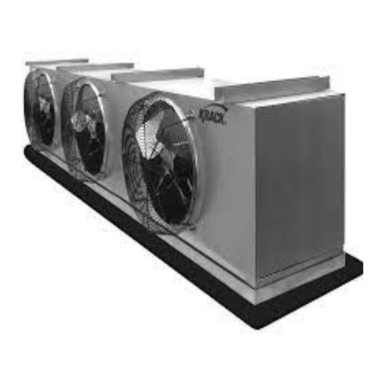
UNIT INFORMATION AND DIMENSIONS MODELS COVERED MS Series medium profile unit coolers. The MS series designed for walk-in coolers with ceiling heights of 10 to 14 feet that require high airflow. The MS series handles medium to low temperature requirements and has three defrost options – air, electric and hot gas. -
Page 6: Unit Dimesion
UNIT DIMENSIONS TABLE 1: UNIT DIMENSIONS Fan Q-ty A 45.00 45.00 57.00 45.00 90.00 102.00 39.00 117.00 129.00 39.00 156.00 168.00 FIGURE 1: UNIT DIMENSIONS MS Series Medium Profile Unit Coolers (E270190_H) -
Page 7: Receipt Of Equipment
2 RECEIPT OF EQUIPMENT INSPECTION All equipment should be carefully checked for damage or shortages as soon as it is received. Each shipment should be carefully checked against the bill of lading. If any damage or shortage is evident, a notation must be made on the delivery receipt before it is signed and a claim should then be filed against the freight carrier. -
Page 8: Check Valve
CHECK VALVE Check valves kit brazed to the pipe at the field, refer to FIGURE 6. TABLE 2: CHECK VALVES KITS Gas Inlet Model Check Valve Kit Diameter 166, 178, 195, 212, 223, 239, 323, 356, 0.500 390, 424 CE269381 444, 445, 487, 502, 532 0.875 594, 602, 643, 669,... -
Page 9: Piping Installation
6 PIPING INSTALLATION DRAIN LINE The drain line should be as short and as steeply pitched as possible with a minimum of ¼” drop per running foot. A drain line trap should be installed to prevent warm moist air from migrating through the drain line. If the temperature surrounding the drain line and trap is below freezing (32) it must be wrapped with a drain line heater and insulation. -
Page 10: Figure 4 Multiple Unit Coolers Controlled By A Single Solenoid
When connecting multiple unit coolers in series using a common suction line, the branch suction lines must enter the top of the common suction line. The branch lines must be sized for the evaporator capacity and the common suction line to be sized for the total system capacity. To properly protect and control systems using pumped liquid overfeed R744, the solenoid, isolation, and pressure relief valves shall be arranged as shown in either FIGURE 4 or 5, according to the solenoid valve arrangement. -
Page 11: Evacuation And Leak Test
EVACUATION AND LEAK TEST When all refrigeration connections have been completed, the entire system must be tested for leaks and then evacuated. Refer to the instructions provided with your systems condensing unit for information on performing the leak test and evacuation. MS GAS DEFROST PIPING FIGURE 6: Gas Defrost Piping Diagrams REFRIGERANT DISTRIBUTOR NOZZLES... - Page 12 DISTRIBUTOR NOZZLE CAPACITIES – TONS OF REFRIGERANT TABLE 1: R404A R407A DISTRIBUTOR NOZZLE EVAPORATOR TEMPERATURE (°F) NUMBER 40° 20° 0° -20° -40° 40° 20° 0° -20° -40° 0.09 0.07 0.05 0.04 0.04 0.11 0.08 0.07 0.06 0.05 0.14 0.11 0.08 0.07 0.05 0.17...
-
Page 13: Electrical
EXPANSION VALVE Before mounting the unit, install the expansion valve and connect the equalizer tube. The expansion valve should be installed directly to the distributor body or as close as possible with no elbows or bends. Locate the expansion valve bulb on a horizontal length of suction line as close to the suction header as possible. Position the bulb in a 3, 4 or 8, 9 o’clock position (do not position on the bottom side of the pipe). -
Page 14: Air Defrost Sequence Of Operation
TABLE 3: (E) EDL HEATERS ELECTRICAL DATA And (P) KGE & (H) HGE HEATERS ELECTRICAL DATA AIR DEFROST SEQUENCE OF OPERATION SEQUENCE OF OPERATION 1. The unit cooler fan motors are energized and the fans operate continually. 2. The room thermostat calls for cooling. The liquid solenoid valve opens allowing liquid to flow to the unit cooler. - Page 15 AIR DEFROST WIRING FIGURE 7: MOTOR TYPE C FIGURE 8: MOTOR TYPE D FIGURE 9: MOTOR TYPE V MS Series Medium Profile Unit Coolers (E270190_H)
-
Page 16: Electric Defrost Sequence Of Operation
ELECTRIC DEFROST SEQUENCE OF OPERATION The electric defrost cycle is time clock initiated and temperature terminated with a timer and or high temperature over-ride. For systems with multiple unit coolers and a single defrost time clock the defrost termination thermostat must be wired in series. Reference FIGURE’s 10 Through 14 for electric defrost wiring diagrams. SEQUENCE OF OPERATION Normal Refrigeration Cycle STEP A:... - Page 17 ELECTRIC DEFROST WIRING WITH DEFROST TIMER FIGURE 10: MOTOR TYPE C FIGURE 11: MOTOR TYPE D FIGURE 12: MOTOR TYPE V MS Series Medium Profile Unit Coolers (E270190_H)
-
Page 18: Figure 13 (E) Edl Electric Defrost Wiring 1 Ph
FIGURE 13: (E) EDL ELECTRIC DEFROST WIRING 1 PH FIGURE 8: (E) EDL ELECTRIC DEFROST WIRING 3 PH GAS DEFROST SEQUENCE OF OPERATION The gas defrost cycle is time is field controller initiated and terminated (H) HGE/(G) HGG THREE PIPE HOT GAS DEFROST Three pipe hot gas defrost systems distribute compressor discharge gas through a separate hot gas line, controlled by a solenoid valve, through a check valve to the refrigerant distributor auxiliary side connection. - Page 19 Step C – When the defrost is complete, the hot gas supply is stopped. The liquid line solenoid is energized, and the coil temperature begins to fall. Step D – The factory mounted thermostat senses the drop in coil temperature. The SPDT thermostat opens the circuit to the drain pan heater (when supplied) and closes the circuit to the fan motors.
-
Page 20: Dual Speed Motor - Sequence Of Operation
FIGURE 17: (P) KGE (2 PIPE) COOL GAS COIL AND ELECTRIC DRAIN PAN WIRING AND (K) KGG (2 PIPE) COOL GAS COIL AND ELECTRIC DRAIN PAN WIRING TWO SPEED MOTOR SEQUENCE OF OPERATION – MS coils use DUAL SPEED EC motors for fans in DOE applications, default being the High speed, the second speed is set as Minimum speed. -
Page 21: Variable Speed Motor Sequence Of Operation
VARIABLE SPEED MOTOR SEQUENCE OF OPERATION Variable speed motor need 0-10V signal from filed, 0-10V signal wires will be connected to terminal allotted in the Evaporator panel (Terminal A0+ & A0-). 0V being the Maximum speed and 10V being minimum speed. -
Page 22: Interlocking Single Compressor Unit With Krack Coils
When Krack Evaporator coils used with Single compressor units from Hussmann (H series and C series), there is provision given to interlock the compressor with evaporator fans. Single compressor units use contactor for compressor operation, a NC Aux contact attached to the main contactor and will be used to interlock. -
Page 23: Start Up
FIGURE 21: VARIABLE SPEED MOTOR EVAPORATER COILS – In Case of Variable speed motor coils – the Jumper between terminal A0+ and A should be removed and then and then aux contact from single compressor unit wired in series. Whenever the compressor contactor energized the Aux contact energizes, and NC contacts changes state to NO, there by OPEN the analog 10V signal circuit. -
Page 24: Preventative Maintenance
For DIRECT EXPANSION systems let the system balance out at the desired room temperature and check the operation of the expansion valve by properly measuring the superheat at the sensing bulb. As much as thirty minutes may be required for the new balance to take place after an adjustment is made. For BRINE or GLYCOL COOLING systems keep the closest vent to the coil open while the fluid fills the coil to allow trapped air to escape. -
Page 25: Fan Guard Or Long Throw Adapter Replacement
FAN GUARD OR LONG THROW ADAPTER REPLACEMENT To remove a fan guard or long throw adapter for fan-motor maintenance, or for guard or adapter replacement, make sure all electrical power to the unit has been turned off before any work is performed. Remove the two nuts on the lowest part of the guard or adapter first. -
Page 26: Troubleshooting Chart
10 TROUBLESHOOTING CHART TABLE 6: TROUBLESHOOTING PROBLEM POSSIBLE CAUSES CORRECTIVE ACTION Fans will not operate. Unit not wired properly. Check wiring. Defective motor. Replace motor. Defective defrost timer, termination Replace defective component. thermostat or fan delay switch. Room temperature too high for use Jumper fan delay switch. - Page 27 TABLE 7: REPLACEMENT PARTS LIST Krack BOM Part Item General Description Options Description Number 1/2HP 208/230/460/50/60/3/11440 11096IN 1/2HP 575/60/3/1140 11506IN 1/2 HP 115/208/230/50/60/1/1075 E316796 MOTOR MOTOR-373W 120-230V 60HZ 1PH 1150-500 2-SPD 3115921 MOTOR MOUNT BF0302000 MOTOR RING 3 PH MTR 56 FRAME 80034 FAN BLADE 20"...
- Page 28 3 FAN ALUM 230/3 V CE270003 3 FAN ALUM 460/3 V CE270049 3 FAN AMUM 575/3 V CE270050 4 FAN ALUM 230/3 V CE270006 4 FAN ALUM 460/3 V CE270052 4 FAM ALUM 575/3 V CE270053 1 FAN GALV 575/3 V CE270113G 2 FAN GALV 230/3 V CE270000G...
- Page 29 Part Number: E270190_F_110918 MS Series Medium Profile Unit Coolers (E270190_H)