ABB FMT400-VTS Operating Instruction
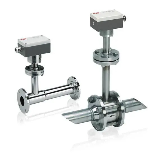
Thermal mass flowmeter
Hide thumbs
Also See for FMT400-VTS:
- Commissioning instructions (32 pages) ,
- Commissioning instructions (264 pages)

Related Manuals for ABB FMT400-VTS


Summary of Contents for ABB FMT400-VTS
- Page 1 Operating instruction Thermal Mass Flowmeter 42/14-36 EN FMT400-VTS, FMT400-VTCS (Sensyflow VT-S/VT-CS) for gases, compact configuration...
- Page 2 Fax: +49 800 1114444 CCC-support.deapr@de.abb.com © Copyright 2006 by ABB Automation Products GmbH We reserve the right to technical amendments This document is protected by copyright. Information in this document is intended only to assist the user in safe and efficient operation of the equipment. Its contents are not to be reproduced in full or part without prior approv- al of legal owner.
-
Page 3: Table Of Contents
Pipe component and weld-on adapter with ball valve ....... 17 Integrated hot tap fitting for FMT400-VTS (Sensyflow VT-S) ......18 4.7.1... -
Page 4: Important Information In Advance
For questions all questions concerning the measuring system, please have the calibration certificate readily at hand. Tel: +49 6023 92-3597 or -3267 Sensyflow Hotline Fax: +49 6023 92-3210 E-mail: sensyflow.deapr@de.abb.com Thermal Mass Flowmeter FMT400-VTS, FMT400-VTCS (Sensyflow VT-S/VT-CS) 42/14-36 EN... -
Page 5: Application According To Designation, General Safety Instructions
2 Application according to designation, general safety instructions Range of application, application according to designation The thermal mass flowmeter FMT400-VTS/-VTCS is designed for flow rate measurements of gas. It is only suit- able to be mounted: • as insertion sensor in a pipe component with flange mounting in pipes of nominal widths from DN 25/1 " to DN 200/8",... -
Page 6: Notes Concerning The Use In Potentially Explosive Areas
Notes concerning the use in potentially explosive areas Only FMT400-VTS is available in a version authorized for use in zone 2 / zone 22. These devices come supplied with an EU declaration of conformity (ATEX). For devices authorized for use in zone 2 / zone 22, only the data and instructions for use stated in the declaration of conformity (ATEX) shall apply. -
Page 7: Instructions Acc. To Directive 97/23/Ec, Pressure Devices
• Fasten the flange screws evenly and with the appropriate torque specified for the built-in gasket. • After mounting the pipe components, close the insertion pipe with an appropriate blind flange with gasket, or close the existing stop valve, if applicable. 42/14-36 EN Thermal Mass Flowmeter FMT400-VTS, FMT400-VTCS (Sensyflow VT-S/VT-CS) - Page 8 • Aggressive fluids may cause corrosion or abrasion which may result in leakage of fluids under pressure. • The flange or process gaskets may become leaky due to material fatigue. Media under pressure might escape then. Thermal Mass Flowmeter FMT400-VTS, FMT400-VTCS (Sensyflow VT-S/VT-CS) 42/14-36 EN...
-
Page 9: Design And Function
Design and function 3 Design and function FMT400-VTS/-VTCS (Sensyflow VT-S/VT-CS) operates on the thermal principle. This measurement method is based on the principle that gas flowing around a heated body absorbs heat from that body.The result of this flow- dependent cooling down process is used as a measurement effect. Since the loss of heat depends on the num- ber of particles reaching the surface of the heated body, it is possible to determine the mass flow directly. -
Page 10: Transducer (Detecting Element)
The transducer is flanged or screwed into pipe component as a plug-in sensor with a centering pin in a defined manner. See also chapter 10, “Technical Data”. Thermal Mass Flowmeter FMT400-VTS, FMT400-VTCS (Sensyflow VT-S/VT-CS) 42/14-36 EN... -
Page 11: Mounting And Installation
• When matching up the detecting element with a weld-on adapter, please read the information in chapter 4.6. Please make sure that the units are easily accessible when they are installed. 42/14-36 EN Thermal Mass Flowmeter FMT400-VTS, FMT400-VTCS (Sensyflow VT-S/VT-CS) -
Page 12: Recommended Steadying Run Lengths For Inlet Run Disturbances
The inlet and outlet run lengths are stated as multiples of the pipe diameter D. For combinations of inlet run disturbances, e. g. valve and reducer, you must always consider the longer inlet run length. Thermal Mass Flowmeter FMT400-VTS, FMT400-VTCS (Sensyflow VT-S/VT-CS) 42/14-36 EN... - Page 13 Under certain circumstances, special calibration can be performed for insufficient steadying lengths. For this purpose and in individual cases, consult the DKD Calibration Department of ABB Automation Products GmbH at Alzenau. An on-site adjustment is also possible, if reference flow values are precisely known, by entering a calibration factor.
-
Page 14: Installation
In the case of the type 1 pipe component (intermediate flange version) with ball valve and a nominal width DN 200 / ANSI 8", transducers with a length of 425 mm must be used. Thermal Mass Flowmeter FMT400-VTS, FMT400-VTCS (Sensyflow VT-S/VT-CS) 42/14-36 EN... -
Page 15: Dimensional Drawings, Version For Process Engineering (Dimensions In Mm)
B3 = Ø115 3“ 78.0 – – – – B4 = 58 4“ 102.4 – – – – 6“ 154.2 – – – 8“ 202.7 – – – > 14“ > 28“ 42/14-36 EN Thermal Mass Flowmeter FMT400-VTS, FMT400-VTCS (Sensyflow VT-S/VT-CS) -
Page 16: Weld-On Adapter
Mounting and installation Weld-on adapter 4.6.1 Weld-on adapter for FMT400-VTS (Sensyflow VT-S) transducer When installing the transducer in pipes with larger nominal width or non-round cross-section, the weld-on adapt- er must be welded to the pipeline under consideration of the following information: The weld-on adapter must have a length L after welding (see Fig. -
Page 17: Pipe Component And Weld-On Adapter With Ball Valve
NOTICE Do not close the ball valve before removing the transducer. Otherwise. the ball may considerably dam- age the cage or the sensor elements. Weld-on adapter with ball valve for FMT400-VTS (Sensyflow VT-S) Weld-on adapter Required accuracy of mounting Sealing ring groove (upon delivery) Centric mounting <... -
Page 18: Integrated Hot Tap Fitting For Fmt400-Vts (Sensyflow Vt-S)
Mounting and installation Integrated hot tap fitting for FMT400-VTS (Sensyflow VT-S) WARNING Safety instructions When dismounting, with more than 1.1 bar absolute pressure, or with high temperatures or health- hazardous gases in the pipe, the use of the exchange tool is recommended and obligatory for safety reasons. -
Page 19: Mounting The Wafer Flange Version
(see Fig. 4-1). Please observe the proper flow direction (arrow on pipe component). Sensyflow- opening Fig. 4-6 Hot tap fitting in disassembly position 42/14-36 EN Thermal Mass Flowmeter FMT400-VTS, FMT400-VTCS (Sensyflow VT-S/VT-CS) -
Page 20: Mounting The Weld-In Version
– Make sure that welded joints do not overheat to prevent warping of the seal surface and damage to the O-rings. You may need to pause and allow the fitting to cool. Thermal Mass Flowmeter FMT400-VTS, FMT400-VTCS (Sensyflow VT-S/VT-CS) 42/14-36 EN... -
Page 21: Mounting The Transducer With System In Operation
(4 units) to secure the guide tube Fig. 4-8 Special screws Lower edge of the lock nut Fig. 4-9 Special screws for covers Fig. 4-10 Transducer with integrated hot top- fitting in measuring position 42/14-36 EN Thermal Mass Flowmeter FMT400-VTS, FMT400-VTCS (Sensyflow VT-S/VT-CS) -
Page 22: Disassembling The Transducer With System In Operation
When working with dusty, abrasive or aggressive measured media, it may be necessary to replace these more frequently. Only ABB Service or qualified personnel of the operator is authorized to replace O-ring gaskets. For the latter case, the warranty is no longer valid for ABB. - Page 23 – Insert the guide tube in the fitting and tighten the 4 hex-head screws of the lock nut until reaching the stop in identical position as with disassembly. – Verify correct installation by rotating the lock nut into measuring and disassembly positions. 42/14-36 EN Thermal Mass Flowmeter FMT400-VTS, FMT400-VTCS (Sensyflow VT-S/VT-CS)
-
Page 24: Fmt400-Vtcs (Sensyflow Vt-Cs), Hygienic Versions
Rd52 × 1/6“ 40 × 1 Rd62 × 1/6“ 52 × 1 Rd78 × 1/6“ 85 × 2 Rd110 × 1/4“ Fig. 4-13 Dimensional drawings hygienic version with pipe fitting S Thermal Mass Flowmeter FMT400-VTS, FMT400-VTCS (Sensyflow VT-S/VT-CS) 42/14-36 EN... - Page 25 Fig. 4-14 Dimensional drawings Hygienic version with FG flange Follow the instructions given in chapter 4.4 to install the transducers in the pipe components. Select the gaskets in accordance with the connection standard used. 42/14-36 EN Thermal Mass Flowmeter FMT400-VTS, FMT400-VTCS (Sensyflow VT-S/VT-CS)
-
Page 26: Connecting Electrical Lines
Fig. 5-2 Power supply 24 V AC / DC + Power supply 24 V AC / DC - Analog output 0/4...20 mA (electrically isolated) + Analog output 0/4...20 mA (electrically isolated) - Thermal Mass Flowmeter FMT400-VTS, FMT400-VTCS (Sensyflow VT-S/VT-CS) 42/14-36 EN... -
Page 27: Connecting The Power Cables
Mark the mains switch accordingly to allow for a clear allocation to the respective equipment. Connect the power cable to the mains. The device may already start up directly upon connection to the mains! 42/14-36 EN Thermal Mass Flowmeter FMT400-VTS, FMT400-VTCS (Sensyflow VT-S/VT-CS) -
Page 28: Start-Up - Safety Instructions
Prior to switching on the device make sure that all steps described in chapter 4 and chapter 5 have been executed properly. Check again that the operating voltage selected on the device is identical with the local mains voltage. After power-on, the device is automatically on. Thermal Mass Flowmeter FMT400-VTS, FMT400-VTCS (Sensyflow VT-S/VT-CS) 42/14-36 EN... -
Page 29: Changing The Configuration
Changing the configuration 7 Changing the configuration The configuration/parameter definition of the FMT400-VTS/-VTCS measuring systems can be modified via LKS adapter (local communication interface) (Fig. 5-1). This adapter is provided separately as an accessory and will be supplied completely with software and appro- priate instructions. -
Page 30: Maintenance
Check the sealing between the detector and pipe component or weld-on adapter for correct status and neatness, and if need be replace sealing with a new one. Process version FMT400-VTS O ring (55 mm × 3 mm) Hygienic version FMT400-VTCS Sealing G acc. to DIN 11851 or... -
Page 31: Technical Data
= 2 s Parameter setting The output signal range of the FMT400-VTS/VTCS flowmeters can be set to either 0...20 mA or 4...20 mA. Additionally, the measuring range window can be extended such that a smaller span corre- sponds to a 20 mA current signal. Alarm signalling is possible at < 3.5 mA or > 22 mA (selectable). - Page 32 24 V DC ± 25 %; 24 V AC ± 25 %, 48...62 Hz Voltage Power consumption < 15 W Current drain < 600 mA, slow-blow fuse of at least 2 A recommended Cable entry M20 x 1.5 Thermal Mass Flowmeter FMT400-VTS, FMT400-VTCS (Sensyflow VT-S/VT-CS) 42/14-36 EN...
-
Page 33: Packaging For Transport
0.2 mm. Adapt the amount of desiccant to the packing volume and the ex- pected transport time (at least sufficient for 3 months). Additionally line the box with a layer of union paper. 42/14-36 EN Thermal Mass Flowmeter FMT400-VTS, FMT400-VTCS (Sensyflow VT-S/VT-CS) -
Page 34: Declarations Of Conformity
Declarations of conformity 12 Declarations of conformity 12.1 Thermal Mass Flowmeter FMT400-VTS 12.2 Declaration of conformity FMT...-.. (Sensyflow) (Sensyflow VT-S) - Pipe component Thermal Mass Flowmeter FMT400-VTS, FMT400-VTCS (Sensyflow VT-S/VT-CS) 42/14-36 EN... - Page 35 ABB has Sales & Customer Support The Company’s policy is one of continuous product expertise in over 100 countries worldwide. improvement and the right is reserved to modify the information contained herein without notice. www.abb.com/flow Printed in the Fed. Rep. of Germany (10.2006) ©...