Advertisement
Quick Links
YASKAWA SMART SERIES
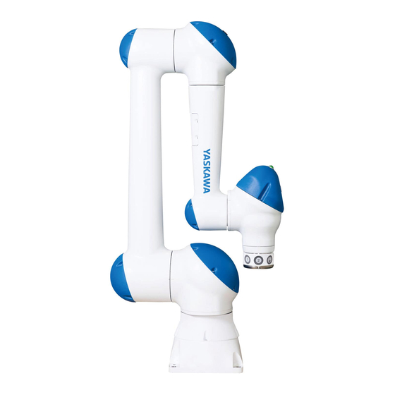
HC10DT COLLABORATIVE ROBOT
QUICK START GUIDE
WITH SMART PENDANT AND YRC1000micro
Upon delivery of the product and prior to operation, read all included instructions thoroughly, and
retain for future reference.
Part Number:
188791-1
Revision:
0
Advertisement

Related Manuals for YASKAWA SMART Series


Summary of Contents for YASKAWA SMART Series
- Page 1 YASKAWA SMART SERIES HC10DT COLLABORATIVE ROBOT QUICK START GUIDE WITH SMART PENDANT AND YRC1000micro Upon delivery of the product and prior to operation, read all included instructions thoroughly, and retain for future reference. Part Number: 188791-1 Revision:...
- Page 2 YASKAWA customers to assist in the operation of the Motoman robots, related equipment and software This manual is copyrighted property of YASKAWA and may not be sold or redistributed in any way. You are welcome to copy this document to your computer or mobile device for...
- Page 3 1.1 Introduction General Information Introduction This is a YASKAWA Smart Series HC10DT Collaborative Robot Quick Start Guide for Robots that have Smart Pendant Version 1.3.5 and newer. This document is intended to guide the user through a basic installation and setup of the Robot and the user to perform basic moves to confirm setup was successful.
- Page 4 188791-1 Smart Series HC10DT Setup HC10DT Smart Series Robot Collaborative Robot 2.1 Transportation Setup HC10DT Smart Series Robot Transportation CAUTION • Use at least two people to transport and unpack the Manipulator and Controller to the installation location • Do not transport the Manipulator and Controller at the same time.
- Page 5 188791-1 Smart Series HC10DT Setup HC10DT Smart Series Robot Collaborative Robot 2.2 Manipulator Installation Manipulator Installation Attach the Manipulator base to the baseplate using four hexagon socket head cap screws M12 (Tensile strength: 1200 N/mm or more, recommended length: 45 mm) by tightening to 84 Nm. The hexagon socket head cap screws and the anchor bolts must be tightened firmly so they do not loosen over time.
- Page 6 188791-1 Smart Series HC10DT Setup HC10DT Smart Series Robot Collaborative Robot 2.3 Controller Installation Controller Installation The Controller can be installed in a 19 inch server rack with compatible hardware (not included). Refer to chapter 3 Installation in the YRC1000micro INSTRUCTIONS detailed instructions on Controller installation.
- Page 7 188791-1 Smart Series HC10DT Setup HC10DT Smart Series Robot Collaborative Robot 2.4 Wiring Robot Wiring Robot 2.4.1 Reference Material Refer to the following manuals for detailed wiring instructions: – READ FIRST!! YRC1000micro GPIO and Direct IN Connections – Section 1.5.2 Connecting to the YRC1000micro of the YRC1000/ YRC1000micro INSTRUCTIONS FOR Smart Pendant –...
- Page 8 188791-1 Smart Series HC10DT Setup HC10DT Smart Series Robot Collaborative Robot 2.4 Wiring Robot 2.4.2.1 Controller Detailed Connectors – The Pendant connects to the bottom section of the Controller as shown Fig. 2-4. – General Purpose I/O (GPIO) connects to the top section of the...
- Page 9 188791-1 Smart Series HC10DT Setup HC10DT Smart Series Robot Collaborative Robot 2.4 Wiring Robot Fig. 2-7: Base I/O Cable Assembly 188791-1...
- Page 10 188791-1 Smart Series HC10DT Setup HC10DT Smart Series Robot Collaborative Robot 2.5 Power ON Power ON WARNING • Perform a risk assessment of the Robot and application before powering ON the Robot. Not performing a risk assessment before Powering ON the Robot may result in death or serious injury.
- Page 11 188791-1 Smart Series HC10DT Setup HC10DT Smart Series Robot Collaborative Robot 2.6 Power OFF Once the startup sequence completes, the Pendant displays the Home screen. Fig. 2-10: Pendant Home Screen If contacting Customer Support, gather all software version information. The software versions are available on the Pendant after starting the Robot: →...
- Page 12 188791-1 Smart Series HC10DT Factory Settings Collaborative Robot Factory Settings WARNING • Review the factory settings and modify them per the application and risk assessment requirements prior to moving the Robot and programming a job. Not modifying the factory settings per the application and risk assessment requirements may result in death or serious injury.
- Page 13 188791-1 Smart Series HC10DT Factory Settings Collaborative Robot 3.1 Modifying Factory Settings Modifying Factory Settings NOTICE “Safety” Access Level is required to edit Safety Settings. → 1. Select “MENU” “Security: Edit” to open the Security Access pop-up. 2. Select the {SAFETY} access level 3.
- Page 14 188791-1 Smart Series HC10DT Factory Settings Collaborative Robot 3.1 Modifying Factory Settings 3.1.1 Changing TCP Speed Complete section 3.1 before to changing the TCP Speed. → → 1. Select “MENU” “Safety Settings” “Safety Functions”. 2. Highlight the Speed Limit file for collaborative operation.
- Page 15 188791-1 Smart Series HC10DT Factory Settings Collaborative Robot 3.1 Modifying Factory Settings 3.1.2 Changing PFL Settings Complete section 3.1 before changing the PFL External Force Monitor Settings. → → 1. Select “MENU” “Safety Settings” “Safety Function” 2. Highlight the External Force Monitor file.
- Page 16 188791-1 Smart Series HC10DT Factory Settings Collaborative Robot 3.2 Torque Sensor Calibration Torque Sensor Calibration For the Collaborative Robot system to function properly, Torque Sensor Calibration must be performed prior to programming the first job and/or mounting any EOAT (End of Arm Tooling) To calibrate the Robot’s torque sensors:...
- Page 17 188791-1 Smart Series HC10DT Factory Settings Collaborative Robot 3.2 Torque Sensor Calibration 4. Verify the “Hand” icon appears in the top corner of the Pendant indicating Manual (Teach) mode. Fig. 3-2: Manual (Teach) Mode 5. Select the Torque Sensor Calibration Position that best suits the installed tool.
- Page 18 188791-1 Smart Series HC10DT Factory Settings Collaborative Robot 3.2 Torque Sensor Calibration 6. Once the Robot reaches the recommended position, go back to the Torque Sensor Calibration screen and notice the “ROBOT AT RECOMMENDED POSITION” is visible in green. Fig. 3-4: Robot at Recommended Position 7.
- Page 19 Jogging Jogging is the most commonly used operation for the Robot. To satisfy the needs under different situations, YASKAWA provides features to help the user to complete the work safely and efficiently. Most jogging features are found on the Robot Jog Panel. The Jog Panel is available from the Job Editing screen by pressing {JOGGING} on the bottom navigation bar and can only be done in Manual (Teach) mode.
- Page 20 188791-1 Smart Series HC10DT Start Using the Robot Collaborative Robot 4.1 Jogging Jog Speed The Pendant provides four levels of speed. For safety reasons, the default speed is set to “Low”. Select the desired speed prior to jogging: NOTICE •...
- Page 21 188791-1 Smart Series HC10DT Troubleshooting and Support Collaborative Robot Troubleshooting and Support Alarms display when an instruction cannot be processed. One or multiple alarms can occur at once. If multiple alarms exist, all pop-ups are shown in a scrollable list. An overview of the alarm layout is provided below. If an alarm occurs during operation, the Robot stops immediately and the ALARM pop-up window appears on the Pendant.
- Page 22 188791-1 Smart Series HC10DT Troubleshooting and Support Collaborative Robot ALARM:4107 “OUT OF RANGE (ABSO DATA) This is the most common alarm that occurs if the Robot determines there is a significant difference in the encoder data (pulse) between power off and power on.
- Page 23 188791-1 Smart Series HC10DT Troubleshooting and Support Collaborative Robot To solve ALARM:4107 “OUT OF RANGE (ABSO DATA)”, perform the following: 1. Press {X HIDE} to conceal the alarm screen. 2. Press {SERVO ON/READY} in TEACH mode. → → 3. Select “MENU”...
- Page 24 188791-1 Smart Series HC10DT Troubleshooting and Support Collaborative Robot Robot Behavior near a Singularity With collaborative operation enabled, the behavior of the robot near a singularity is limited to single axis moves (i.e. no move(s) that involve simultaneous motion of multiple axes).
- Page 25 188791-1 Smart Series HC10DT Troubleshooting and Support Collaborative Robot PFL Function When enabled, the collaborative PFL (Power and Force Limiting) function will stop Robot motion according to measured external forces. The PFL function monitors the external forces acting on the TCP and each axis of the manipulator.
- Page 26 188791-1 Smart Series HC10DT Troubleshooting and Support Collaborative Robot Escape from Clamping Function When enabled, the PFL function described above starts the stop position monitoring in which the Robot is not operable if an object is clamped (stuck) between the manipulator and surrounding environment or between the joints of the manipulator.
- Page 27 READ FIRST!! YRC1000micro GPIO and Direct-IN Connections Customer Support If needing assistance with any aspect of the Smart Series HC10DT Collaborative Robot, contact a local Customer Support using the information on the back cover. When calling, have the following information available: •...
- Page 28 HC10DT COLLABORATIVE ROBOT QUICK START GUIDE WITH SMART PENDANT AND YRC1000micro For inquiries or after-sales service on this product, contact your local YASKAWA representative as shown below. YASKAWA ELECTRIC CORPORATION 2-1 Kurosakishiroishi, Yahatanishi-ku, Kitakyushu, 806-0004, Japan Phone: +81-93-645-7703 Fax: +81-93-645-7802 http://www.yaskawa.co.jp...