
Related Manuals for Akai X-201D


Summary of Contents for Akai X-201D
- Page 1 OPERATOR’S MANUAL STEREO TAPE DECK MA N U FA C T U R E D & D I S TR I B U T ED B Y A K A I E LE C T R IC C O . . LT D . / A K A I TR A D IN G C O . . LT D. / A KA I A M E R IC A...
-
Page 2: Table Of Contents
INDEX CEE, CSA and UL standard models are not equipped Controls................. 2 with a Voltage Selector or Cycle Conversion Switches. Cross-Field Head Recording System ........5 Therefore, voltage and cycle conversion is not neces Voltage & Cycle Conversion..........6 sary. If your machine corresponds to any of these Tape Loading................ -
Page 3: Controls
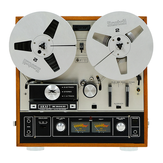
CONTROLS INDEX COUNTER & RESET BUTTON SUPPLY REEL TABLE BUILT-IN REEL RETAINER Locks reel firmly into place. TAPE SPEED SELECTOR Set this Selector and the Equalizer Switch to corresponding speed. CYCLE CONVERSION SWITCH (A) Out position : SO Hz., In position : 60 Hz. Set this switch and Cycle Conversion Switch (B) to correspond with are3 power source. - Page 4 SENSING POLE AUTOMATIC SHUT-OFF LEVER Inter-connected with Automatic Stop/Shut-Off Switch Automatic Stop/Shut-Off. TAKE-UP REEL TABLE BUILT-IN REEL RETALNER Locks reel firmly into place. PLAYBACK/RECORD LEVER Advances tape for playback or recording mode. AUTOMATIC STOP/SHUT-OFF SWITCH FAST FORWARD/REWIND LEVER Advances and rewinds tape at fast speed. PAUSE LEVER For temporarily suspending tape travel during recording or playback.
- Page 5 UNIVERSAL VOLTAGE SELECTOR CYCLE CONVERSION SWITCH (B) FUSE POST AC CORD Fig. 2 DIN JACK HIGH/LOW INPUT SWITCH DIN JACK LINE OUTPUT JACKS (LEFT/RIGHT) LINE INPUT JACKS (LEFT/RIGHT)
-
Page 6: Cross-Field Head Recording System
Diagram 1. Ordinary recording system SIGNAL & BIAS Diagram 2. Cross-field recording syatem SIGNAL CROSS FIELD HEAD BIAS Fig. 4 CROSS-FIELD HEAD RECORDING SYSTEM On conventional recorders, the signal and bias are applied to the same recording head. Therefore, the frequencies recorded, especially high frequency signals, tend to be attenuated or erased by the effect of the bias field. -
Page 7: Voltage & Cycle Conversion
VOLTAGE & CYCLE CONVERSION VOLTAGE Your machine is equipped with a universal voltage selector offering six selections of voltage from 100 V to 240 V AC for use anywhere in the world. Voltage is preset at the factory according to destination. Please confirm setting prior to operation and if readjustment is necessary, proceed as follows : Disconnect power cord and remove the Fuse Post by... -
Page 8: Tape Speed Selection & Equalizer
To release depress the Start Button. * Pause control does not function during fast forward or rewind mode. MONITORING For monitoring, connect stereo headphones to Headphone Jack. Use stereo headphones of low (8 £2) impedance. Akai model ASE-22 or ASE-20 is highly recommended. -
Page 9: 4-Track Recording/Playback System
Selector to 3-2. The third monaural recording and playback existing trouble and contact your nearest author takes place on track 3, and the fourth on track 2 after the ized Akai Service Station or the Service Dept, of reels have been inverted. Akai Company, Tokyo, Japan. -
Page 10: Playback
PLAYBACK For playback of recorded tapes connect the Line outputs to the tape inputs of your stereo amplifier and connect a pair of speakers to the amplifier. Connect power cord and load a pre-recorded tape. STEREO PLAYBACK (A) Turn on Power Switch. (B) Set Track Selector to STEREO position. -
Page 11: Recording From Microphones
RECORDING FROM MICROPHONES STEREO RECORDING Connect power cord and load a tape. New tape gives best results. (A) Turn on Power Switch. ( B) Set Track Selector to STEREO position. (C) Set Jape Speed Selector and Equalizer to desired speed. (I)) With Reset Button, set Index Counter to ‘*0000”. -
Page 12: Recording From An External Amplifier
For erasing only, thread the tape and set recorder to normal recording mode. No plugs should be connected to the input jacks. Akai Model ATE-7 Tape Fig. 21 Eraser is recommended for complete tape erasure. -
Page 13: Head Cleaning
Remove the Head Cover and with a stiff cotton swab dipped in cleaning fluid ( Akai Head C leaning Kit HC-500 is highly recommended) rub the entire head surface (do not scratch) until all tape oxide and dust are removed. -
Page 14: Technical Data
STANDARD ACCESSORIES Connection Cord..............1 Sensing Tape ..............1 Spare Fuse................1 set Operator’s Manual .............. I OPTIONAL ACCESSORIES UM-101 ATE-7 AS-3 Unt-Dircctional Dynamic Microphone Tape Eraser Tape Splicer DM-13 AH-8 Non-Directional Dynamic Microphone Head Demagnet izcr Head Cleaning Kit... - Page 15 AA-5800 SW-175 Stereo Pre-main Amplifier Stereo Headphones Speaker System AA-5500 ASE-20 SW-155 Stereo Pre-main Amplifier Stereo Headphones Speaker System...
- Page 16 Max. 18 cm Spulengrößen: Akai Receiver. Verstärker, Hl Fl Lautsprecherboxen und das Sonder-Zubehör sind passend für Akai Tonbandgeräte konstruiert. Weiteres Informationsmaterial erhalten Sie von Akai International GmbH, 6079 Buchschlag, Am Siebenstein 4. Im Sinne einer kontinuierlichen technischen Verbesserung des Produktes behalten wir uns das Recht vor, technische Veränderungen ohne vorherige Ankündigungen vorzunehmen, ohne daß...