FujiFilm FCR XG-1 Operation Manual
Hide thumbs
Also See for FCR XG-1:
- Service manual (1092 pages) ,
- Operation manual (88 pages) ,
- Service manual (20 pages)
Table of Contents
Advertisement
Quick Links
- 1 Features of the Fujifilm Fcr
- 2 Hardware Configuration
- 3 Starting up and Shutting down the System
- 4 Step 7 Inserting the Cassette (Starting Reading the Ip)/Removing the Cassette
- 5 Step 8 Qa Operations
- 6 Step 9 Image Output
- 7 Conducting Exposure Using a Cassette (Ip) Left Unused for 8 Hours or more [Secondary Exposure]
- 8 Removing Dust
- Download this manual
Advertisement
Table of Contents

Related Manuals for FujiFilm FCR XG-1


Summary of Contents for FujiFilm FCR XG-1
- Page 1 FCR XG-1 (CR-IR346RU) Operation Manual Third Edition: September 2001 Fuji Photo Film Co., Ltd. 010-021-20 09.2001...
- Page 2 The "FUJIFILM FCR XG-1 Operation Manual" (this manual, hereinafter) describes in detail operation methods and usage precautions so that FCR XG-1 functions can be used correctly and more efficiently. First-time users of this system should first read this manual thoroughly and then store it near the device and refer to it regularly for optimum use of the system.
- Page 3 Contents at a Glance Chapter 1 Introduction Chapter 2 Operations Chapter 3 When an Error Occurs Appendix A Specifications Appendix B IP Handling Appendix C Film Annotation Appendix Y Exposed Anatomical Regions / Applicable Menus / Display Parameters Appendix Z Precautions for Exposure 010-021-20 09.2001...
-
Page 4: Table Of Contents
Contents Chapter 1 Introduction ......................1.1 Features of the FUJIFILM FCR XG-1 ..............1.2 Operational Precautions ..................1.2.1 Laser Handling Precautions ............... 1.2.2 Preventing Electric Shock ................1.2.3 Electromagnetic Compatibility (EMC) ............1.2.4 Signal Input and Output Parts ..............1.2.5 Usage Precautions .................. - Page 5 Chapter 3 When an Error Occurs ..................3.1 When an Error Occurs ..................Appendix A Specifications ....................1 Processing Capacity ....................2 Image Reading ......................3 Image Output ....................... 4 Power Supply Conditions .................... 5 Environmental Conditions ................... 6 External Dimensions and Weight ................7 CR-IR346RU External View ..................
- Page 6 010-021-20 09.2001...
-
Page 7: Chapter 1 Introduction
Chapter 1 Introduction 010-021-20 09.2001... -
Page 8: Features Of The Fujifilm Fcr
Introduction Features of the FUJIFILM FCR XG-1 The FUJI Computed Radiography System FCR XG-1 performs Digital Radiography by using an Imaging Plate (IP) as the X-ray detection device. It reads and processes X-ray image information that is recorded on an IP exposed using a cassette-type X-ray stand and can also print out hard copies on film using the connected image recorder. -
Page 9: Operational Precautions
Introduction Operational Precautions 1.2.1 Laser Handling Precautions CR-IR346RU Laser Unit Specifications Class IIIb Medium Semiconductor laser Wavelength 660 nm Maximum Output 50 mW (CW) WARNING: The CR-IR346RU incorporates a Class IIIb laser with maximum output of 50mW. To prevent exposure to its laser beams, observe the following precautions. •... -
Page 10: Signal Input And Output Parts
Introduction 1.2.4 Signal Input and Output Parts Rear of machine AC-IN 100~240V IIP-LAN CR-IR 346CL-LAN : Connected to the image and ID network devices. 10base-T/100base-TX interface * Service engineers take responsibility for connections of these devices. 010-021-20 09.2001... -
Page 11: Usage Precautions
Introduction 1.2.5 Usage Precautions We ask that you heed these usage precautions and use the equipment correctly. 1. This equipment should be used only by people who have the proper skills. 2. Heed the following precautions when installing the equipment. 2-1. -
Page 12: Location Of Hhs Labels
Introduction 1.2.6 Location of HHS Labels <Right Side> <Left Side and Rear> HHS Label #1 HHS Certification and EN60825-1:1996 Identification Label Class IIIb Panel Label HHS Label #1 HHS Label #1 EN60825-1:1996 Class 1 Product Label EN60825-1:1996 Class IIIb Panel Label EN60825-1:1996 Class IIIb Panel Label FUJI PHOTO FILM CO., LTD. -
Page 13: Safety Precautions
Introduction Safety Precautions This section contains safety precautions required for the safe operation of this equipment. Carefully read and follow these precautions before using the equipment. If these precautions are not followed, injury or damage to the equipment may occur. Safety precautions are marked as WARNING or CAUTION and additional information as “... -
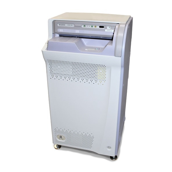
Page 14: Hardware Configuration
Introduction Hardware Configuration 1.4.1 Unit Names and Functions The external view of the FCR XG-1 and the names of the components are shown below. [Fig. 1.1] FCR XG-1 <External View and Component Names> CALL Lamp Processing Status POWER Lamp Lamps... - Page 15 Introduction [ Table 1-1 ] FCR XG-1 Component Names and Functions Name Function Operation Panel Operation panel for the CR-IR346RU. POWER Lamp Lights (green) when the circuit breaker has been set to the “I” side and the power turned ON. As the circuit breaker is basically left ON, the POWER Lamp will also basically be lit.
-
Page 16: Routine Operation Flowchart
Introduction Routine Operation Flowchart The routine operation flowchart for the FCR XG-1 system is as follows. [Fig. 1.2] Routine Operation Flowchart X-ray exposure CR-IR346RU CR Console Study No./patient ID entry Cassette insertion (Image reading) Exposure menu selection Image data Image Recorder... -
Page 17: Chapter 2 Operations
Chapter 2 Operations 010-021-20 09.2001... -
Page 18: Starting Up And Shutting Down The System
Operations Starting Up and Shutting Down the System How to start up and shut down this system will differ whether the power to the CR–IR346CL and CR-IR346RU is interlocked with each other or not. 2.1.1 When the Power ON/OFF Sequences are Interlocked Starting Up the System 1 Start up the CR Console. - Page 19 2 The CR Console application software starts up, then the CR-IR346RU. When both the CR-IR346RU POWER LAMP and the CR Console Image Reading Unit Monitor lamp go ON, startup of the FCR XG-1 has been fully completed as a system. [ Fig. 2.2 ] CR Console Display Immediately After Startup The POWER LAMP is ON.
-
Page 20: Shutting Down The System
Operations Shutting Down the System 1 Confirm on the CR-IR346RU that cassette processing has been completed. If the cassette remains in the cassette setting unit, remove it. [ Fig. 2.3 ] Removing the Cassette 2 Shut down the CR Console. (For detailed operation procedures, see the [CR Console Operation Manual].) The CR-IR346RU will then be in standby status automatically. -
Page 21: When The Power On/Off Sequences Are Not Interlocked
Operations 2.1.2 When the Power ON/OFF Sequences are Not Interlocked Starting Up the System 1 Start up the CR Console. (For detailed operation procedures, see the [CR Console Operation Manual].) The CR Console application software will start up. [ Fig. 2.5 ] CR Console Startup Power ON/OFF switch 010-021-20 09.2001... - Page 22 2 Push the CR-IR346RU circuit breaker to the "I" side for turning the power ON. When both the CR-IR346RU POWER LAMP and the CR Console Image Reading Unit Monitor lamp turn ON, startup of the FCR XG-1 has been completed as a system. [ Fig. 2.6 ] CR Console Display Immediately After Startup When a multiple number of Reading Units, including this device (CR-IR346RU), are connected, the status display changes to that shown below.
-
Page 23: Shutting Down The System
Operations Shutting Down the System 1 Shut down the CR Console. (For detailed operation procedures, see the [CR Console Operation Manual].) [Fig. 2.7] Shutting Down the CR Console Touch this button. Touch this button. 2 Confirm on the CR-IR346RU that cassette processing has been completed. If the cassette remains in the cassette setting unit, remove it. -
Page 24: Routine Operations
Operations 2.2 Routine Operations FCR XG-1 routine operations can be broadly divided into the following ten steps. Step 1 X-ray Exposure (See p. 2-9.) Step 2 Entering Accession No. and Patient's ID Data (See p. 2-9.) Step 3 Selecting the Exposure Menu (See p. - Page 25 Operations X-ray Exposure Step 1 Using a cassette that contains an erased IP, conduct X-ray exposure using the same tech- nique as for the conventional film/screen method. For precautions particular to exposure using the FCR system, see Appendix Z, Precautions for Exposure.
- Page 26 Operations Selecting the Exposure Menu Step 3 Select (touch) the target exposure menu on the "Exposure Menu Selection" screen, then touch the button on the lower right. (For detailed operation procedures, see the [CR Console Operation Manual].) [ Fig. 2.11 ] Exposure Menu Selection Screen Select (touch) the tab for a desired ana-...
- Page 27 Operations Changing the Parameters Step 5 Once the reception of studies has been completed, the "Start Study" screen like that shown below will appear. If [Reserve Study] is selected at above, touch the "Study Reservation" Step 4 tab to display the reservation list. Select then the target study and touch (execution key).
- Page 28 Operations Reading the IP Barcode Step 6 Perform this step only when a multiple number of Reading Units, including this device (CR-IR346RU), are connected to the CR Console. To read the IP barcode, use the dedicated barcode reader connected to the CR Console. A beep will sound to indicate the completion of IP barcode reading.
-
Page 29: Step 7 Inserting The Cassette (Starting Reading The Ip)/Removing The Cassette
Operations Inserting the Cassette (Starting Reading the IP)/Removing the Cassette Step 7 Inserting the Cassette Insert the cassette (IP) that has been subjected to exposure into the cassette setting unit. 1 Confirm that the Cassette Insertion Ready Lamp on the operation panel has been lit (green). -
Page 30: Precautions When Inserting The Cassette
Operations Precautions when inserting the cassette Slowly Make sure to insert the cassette so that it is straight along the guide on the right. Cassette guide Insert straight Slowly. CAUTION: Never insert a cassette as illustrated below or damage to the device could result. Incorrect: Cassette is not straight along the guide. -
Page 31: Removing The Cassette
Operations Removing the Cassette slowly Confirm that the Cassette Removal Lamp has been lit. Remove then the cassette and use it for the next exposure. [ Fig. 2.15 ] Removing the Cassette Cassette Removal Lamp must be ON. 2-15 010-021-20 09.2001... -
Page 32: Step 8 Qa Operations
Operations QA Operations Step 8 The image read by the CR-IR346RU will be displayed on the CR Console monitor (left half of the screen). When the image reading is completed, the thumbnail images will then be dis- played in the exposure menu display area on the right half of the screen. Touch the (QA) button on the bottom of the screen. -
Page 33: Step 9 Image Output
Operations Image Output Step 9 Touch the (Print) button. Command will be transmitted to the specified device (printer, etc.) for outputting the image. Completing the Study Step 10 When a series of studies is completed, touch the (Study Completed) button to fully complete it. -
Page 34: Conducting Exposure Using A Cassette (Ip) Left Unused For 8 Hours Or More [Secondary Exposure]
Operations Conducting Exposure Using a Cassette (IP) Left Unused for 8 Hours or More [SECONDARY ERASURE] When conducting exposure with a cassette (IP) that has not been used for 8 hours or more, the cassette (IP) should be subjected to "Secondary Erasure Processing" for erasing such excess energy as natural radioactive rays accumulated on the IP. -
Page 35: Conducting Image Erasure Only [Primary Erasure]
Operations Conducting Image Erasure Only [Primary Erasure] To erase an image on IP --- owing to exposure errors, etc. --- without reading it, use the following procedure to conduct "Primary Erasure Processing." Operation procedures follow. 1 Press the Erasure Selection Switch twice to select "Primary Erasure Processing." Pressing this button once will select "Secondary Erasure Processing."... -
Page 36: Removing Dust
Operations Removing Dust Regularly remove dust accumulated inside the Reading Unit using the procedure below. Touch the Utility button on the right of the Reading Unit status display area. When the following menu appears, touch the Dust Removal button. This procedure will be completed in about 15 seconds. Touch this button. - Page 37 Chapter 3 When an Error Occurs 010-021-20 09.2001...
- Page 38 When an Error Occurs When an Error Occurs When an error occurs in the Reading Unit (CR-IR346RU) or the CR Console, the CR-IR346RU alarm will sound and the CALL lamp light (yellow). In this case, the relevant error message will be displayed on the CR Console monitor. Check the displayed message on the monitor to take appropriate countermeasures in accordance with the separate [CR Console Operation Manual] as required.
- Page 39 Appendix A Specifications 010-021-20 09.2001...
- Page 40 Specifications 1 Processing Capacity (1) Processing Capacity With ST-VI IP q q q q q w w w w w e e e e e r r r r r With FM-DP L With FM-DP L With DRYPIX 1000 With FM-DP 2636 14 ×...
- Page 41 Specifications 2 Image Reading (1) Available IP types and sizes VI (standard type): 1. Inch settings 14" × 17", 14" × 14", 10" × 12", 8" × 10" 2. Metric settings VI (standard type): 35 × 43cm, 35 × 35cm, 24 ×...
- Page 42 Specifications 3 Image Output (1) Film output at the Image Recorder Connection to the Image Recorder will make it possible to obtain hard copy in the follow- ing image reduction ratios and formats. For standard pixel-density images Reading size Reduction ratio Two-image output One-image output 14 ×...
- Page 43 Specifications 4 Power Supply Conditions Image reader (CR-IR346RU) 100-120 / 200 – 240VAC±10% Single phase 50/60Hz: 5 Environmental Conditions (1) Operating Conditions Temperature: 15-30°C Humidity: 40-80%RH (No dew condensation) (2) Non-Operating Conditions Temperature: 0-45°C Humidity: 10-90%RH (No dew condensation) 6 External Dimensions and Weight Width (mm) Depth (mm) Height (mm)
- Page 44 Specifications 7 CR-IR346RU External View [Fig. A.2] Image Reader main unit Unit: mm <Left-side> <Front> <Right-side> <Rear> 010-021-20 09.2001...
- Page 45 Specifications 8 CR Console External View [Fig. A.3] Console Unit (1) PC main unit and keyboard (Unit: mm) (2) Display (LCD) (3) Display (CRT) 010-021-20 09.2001...
- Page 46 Specifications 010-021-20 09.2001...
- Page 47 Appendix B IP Handling 010-021-20 09.2001...
- Page 48 IP Handling IP Erasure Processing Secondary Erasure Even when stored in a room, an IP is very sensitive and absorbs and accumulates natural radioactivity such as cosmic rays or radiation energy emanating from radioisotopes con- tained in construction materials such as those used for floors and walls. Perform secondary erasure for IPs which have not been used that day.
- Page 49 IP Handling Cleaning (1) Materials required Lint free non-woven cotton Gauze (100% cotton), Lens cleaner such as Toraysee ® (2) Method 1 With a dry cloth of materials listed above, wipe off the IP surface as illustrated below (A or B). 2 For stains which fail to come off by cleaning with dry cleaning cloths, dampen the above cloth with ethanol anhydride (JIS standards or special standards) before clean- ing.
- Page 50 IP Handling 010-021-20 09.2001...
- Page 51 Appendix C Film Annotation 010-021-20 09.2001...
- Page 52 Film Annotation Basic layout of the film annotation printed on output film and the meanings are explained below. [Fig. C.1] Initially Set Film Annotation Character display position can differ slightly from the sample above. 010-021-20 09.2001...
- Page 53 Film Annotation [Table. C-1] Initially Set Film Annotaiton Name Meaning (1) Hospital name The name of the hospital (or medical institution) will be displayed. (medical institution name) (2) EDR mode and menu code The EDR mode and the menu code will be displayed. (* Only the menu code will be displayed in the Standard Film Annotation.) (3) System ID and image No.
- Page 54 Film Annotation 010-021-20 09.2001...
- Page 55 Appendix Y Exposed Anatomical Regions/ Applicable Menus/Display Parameters 010-021-20 09.2001...
- Page 56 Exposed Anatomical Regions/Applicable Menus/Display Parameters [ Head 1 ] Menu Applicable projection method (PA) : Right-to-left Remarks and observation site reversed output Observation of the entire skull and facial bone, entire cerebral SKULL, GENERAL 0000 ventricles and paranasal sinus, and gnathic joint and Turkish (PA) saddle by the Towne projection and Caldwell method Observation of the nasal cavity and its surroundings by...
- Page 57 Exposed Anatomical Regions/Applicable Menus/Display Parameters Gradation Processing Rotation Amount (GA) EDR mode Display Parameter Gradation Type (GT) Rotation Center (GC) Gradation Shifting Amount (GS) Frequency Processing Frequency Rank (RN) Two-image Display Frequency Type (RT) Auto Semi Frequency Enhancement (RE) Preset Left Image Right Image One-image Display...
- Page 58 Exposed Anatomical Regions/Applicable Menus/Display Parameters [ Head 2 ] Menu Applicable projection method (PA) : Right-to-left Remarks and observation site reversed output Panagraphy PANAGRAPHY 0009 (PA) Tomography of the entire skull of infants by low-dose SKULL, PED. -1 0016 exposure (PA) Pantomography PANTOMO.
- Page 59 Exposed Anatomical Regions/Applicable Menus/Display Parameters Gradation Processing Rotation Amount (GA) EDR mode Display Parameter Gradation Type (GT) Rotation Center (GC) Gradation Shifting Amount (GS) Frequency Processing Frequency Rank (RN) Two-image Display Frequency Type (RT) Auto Semi Frequency Enhancement (RE) Preset Left Image Right Image One-image Display...
- Page 60 Exposed Anatomical Regions/Applicable Menus/Display Parameters [ Neck ] Menu Applicable projection method (PA) : Right-to-left Remarks and observation site reversed output Exposure of the whole neck; observation of the neck CERVICAL, GENERAL 0100 from the cervical spine to soft parts (AP) Observation of the frontal portion of the pharynx and larynx Observation of the cervical spine, except through open...
- Page 61 Exposed Anatomical Regions/Applicable Menus/Display Parameters Gradation Processing Rotation Amount (GA) EDR mode Display Parameter Gradation Type (GT) Rotation Center (GC) Gradation Shifting Amount (GS) Frequency Processing Frequency Rank (RN) Two-image Display Frequency Type (RT) Auto Semi Frequency Enhancement (RE) Preset Left Image Right Image One-image Display...
- Page 62 Exposed Anatomical Regions/Applicable Menus/Display Parameters [ Chest 1 ] Menu Applicable projection method (PA) : Right-to-left Remarks and observation site reversed output Plain thoracic exposure; observation of the lung field CHEST, GENERAL 0200 and mediastinum for shadows (PA) For exposure of the thoracolumbar spine, use the Observation of the thoracic and cervicothoracic spines THORA.
- Page 63 Exposed Anatomical Regions/Applicable Menus/Display Parameters Gradation Processing Rotation Amount (GA) EDR mode Display Parameter Gradation Type (GT) Rotation Center (GC) Gradation Shifting Amount (GS) Frequency Processing Frequency Rank (RN) Two-image Display Frequency Type (RT) Auto Semi Frequency Enhancement (RE) Preset Left Image Right Image One-image Display...
- Page 64 Exposed Anatomical Regions/Applicable Menus/Display Parameters [ Chest 2 ] Menu Applicable projection method (PA) : Right-to-left Remarks and observation site reversed output Sternal tomography STERNUM 2202 (AP) Thoracic spinal tomography For tomography of the cervicothoracic THORA. SPINE, FRN 2203 spines, use the 2500 “LUMBAR SPINE” (AP) menu.
- Page 65 Exposed Anatomical Regions/Applicable Menus/Display Parameters Gradation Processing Rotation Amount (GA) EDR mode Display Parameter Gradation Type (GT) Rotation Center (GC) Gradation Shifting Amount (GS) Frequency Processing Frequency Rank (RN) Two-image Display Frequency Type (RT) Auto Semi Frequency Enhancement (RE) Preset Left Image Right Image One-image Display...
- Page 66 Exposed Anatomical Regions/Applicable Menus/Display Parameters [ Breast ] Menu Applicable projection method (PA) : Right-to-left Remarks and observation site reversed output Observation of the whole breast Use the Mo bulb. BREAST 0300 Available for other exposures including spot exposure (AP) Observation of the breast including the chest wall or Use the Mo bulb.
- Page 67 Exposed Anatomical Regions/Applicable Menus/Display Parameters Gradation Processing Rotation Amount (GA) EDR mode Display Parameter Gradation Type (GT) Rotation Center (GC) Gradation Shifting Amount (GS) Frequency Processing Frequency Rank (RN) Two-image Display Frequency Type (RT) Auto Semi Frequency Enhancement (RE) Preset Left Image Right Image One-image Display...
- Page 68 Exposed Anatomical Regions/Applicable Menus/Display Parameters [ Abdomen ] Menu Applicable projection method (PA) : Right-to-left Remarks and observation site reversed output Plain abdominal exposure; observation of the whole ABDOMEN, GENERAL 0400 abdomen; thoracicoabdominal exposure (AP) Observation of the abdomen and pelvic part of infants ABDOM., PEDIATRICS 0402 (3 years old or less);...
- Page 69 Exposed Anatomical Regions/Applicable Menus/Display Parameters Gradation Processing Rotation Amount (GA) EDR mode Display Parameter Gradation Type (GT) Rotation Center (GC) Gradation Shifting Amount (GS) Frequency Processing Frequency Rank (RN) Two-image Display Frequency Type (RT) Auto Semi Frequency Enhancement (RE) Preset Left Image Right Image One-image Display...
- Page 70 Exposed Anatomical Regions/Applicable Menus/Display Parameters [ Pelvis 1 ] Menu Applicable projection method (PA) : Right-to-left Remarks and observation site reversed output Observation of the pelvis, ilium, and peripheral soft PELVIS, GENERAL 0500 parts (AP) Observation of the lumbar and thoracolumbar spine LUMBAR SPINE 0501 (AP)
- Page 71 Exposed Anatomical Regions/Applicable Menus/Display Parameters Gradation Processing Rotation Amount (GA) EDR mode Display Parameter Gradation Type (GT) Rotation Center (GC) Gradation Shifting Amount (GS) Frequency Processing Frequency Rank (RN) Two-image Display Frequency Type (RT) Auto Semi Frequency Enhancement (RE) Preset Left Image Right Image One-image Display...
- Page 72 Exposed Anatomical Regions/Applicable Menus/Display Parameters [ Pelvis 2 ] Menu Applicable projection method (PA) : Right-to-left Remarks and observation site reversed output Uterus and salpinx exposure with a constrast medium HYSTERO. 1502 (AP) Seminal vesicle and seminal duct exposure with a SEMI.
- Page 73 Exposed Anatomical Regions/Applicable Menus/Display Parameters Gradation Processing Rotation Amount (GA) EDR mode Display Parameter Gradation Type (GT) Rotation Center (GC) Gradation Shifting Amount (GS) Frequency Processing Frequency Rank (RN) Two-image Display Frequency Type (RT) Auto Semi Frequency Enhancement (RE) Preset Left Image Right Image One-image Display...
- Page 74 Exposed Anatomical Regions/Applicable Menus/Display Parameters [ Upper Extremity 1 ] Menu Applicable projection method (PA) : Right-to-left Remarks and observation site reversed output Observation of the humerus, its soft part, and the UP. ARM/ELBOW JNT 0600 elbow joint (AP) Observation of the antebrachial bone, its soft part, and FO.
- Page 75 Exposed Anatomical Regions/Applicable Menus/Display Parameters Gradation Processing Rotation Amount (GA) EDR mode Display Parameter Gradation Type (GT) Rotation Center (GC) Gradation Shifting Amount (GS) Frequency Processing Frequency Rank (RN) Two-image Display Frequency Type (RT) Auto Semi Frequency Enhancement (RE) Preset Left Image Right Image One-image Display...
- Page 76 Exposed Anatomical Regions/Applicable Menus/Display Parameters [ Upper Extremity 2 ] Menu Applicable projection method (PA) : Right-to-left Remarks and observation site reversed output 3× or more magnification of the phalanges and other UP. EXTREMITY, MAG 4607 bones (AP) Y-22 010-021-20 09.2001...
- Page 77 Exposed Anatomical Regions/Applicable Menus/Display Parameters Gradation Processing Rotation Amount (GA) EDR mode Display Parameter Gradation Type (GT) Rotation Center (GC) Gradation Shifting Amount (GS) Frequency Processing Frequency Rank (RN) Two-image Display Frequency Type (RT) Auto Semi Frequency Enhancement (RE) Preset Left Image Right Image One-image Display...
- Page 78 Exposed Anatomical Regions/Applicable Menus/Display Parameters [ Lower Extremity 1 ] Menu Applicable projection method (PA) : Right-to-left Remarks and observation site reversed output Observation of the femoral bone, soft tissues and the THIGH/KNEE JOINT 0700 knee (It should be noted however that knee joint (AP) observation by axial projection is excluded.) Observation of the crural bone and soft part...
- Page 79 Exposed Anatomical Regions/Applicable Menus/Display Parameters Gradation Processing Rotation Amount (GA) EDR mode Display Parameter Gradation Type (GT) Rotation Center (GC) Gradation Shifting Amount (GS) Frequency Processing Frequency Rank (RN) Two-image Display Frequency Type (RT) Auto Semi Frequency Enhancement (RE) Preset Left Image Right Image One-image Display...
- Page 80 Exposed Anatomical Regions/Applicable Menus/Display Parameters [ Lower Extremity 2 ] Menu Applicable projection method (PA) : Right-to-left Remarks and observation site reversed output Ankle joint exposure with a contrast medium ANKLE JNT, ARTHRO 1722 (AP) Exposure of patellar with a contrast medium by axial PATL.
- Page 81 Exposed Anatomical Regions/Applicable Menus/Display Parameters Gradation Processing Rotation Amount (GA) EDR mode Display Parameter Gradation Type (GT) Rotation Center (GC) Gradation Shifting Amount (GS) Frequency Processing Frequency Rank (RN) Two-image Display Frequency Type (RT) Auto Semi Frequency Enhancement (RE) Preset Left Image Right Image One-image Display...
- Page 82 Exposed Anatomical Regions/Applicable Menus/Display Parameters [ Test 1 ] Menu Applicable projection method (PA) : Right-to-left Remarks and observation site reversed output SENSITIVITY 0900 SHARPNESS 0901 LINEARITY 0902 IMAGE-FORMAT 0903 CONTRAST 0904 MAX 0.5 0905 MAX 1.0 0906 MAX 2.0 0907 MAX 3.0 0908...
- Page 83 Exposed Anatomical Regions/Applicable Menus/Display Parameters Gradation Processing Rotation Amount (GA) EDR mode Display Parameter Gradation Type (GT) Rotation Center (GC) Gradation Shifting Amount (GS) Frequency Processing Frequency Rank (RN) Two-image Display Frequency Type (RT) Auto Semi Frequency Enhancement (RE) Preset Left Image Right Image One-image Display...
- Page 84 Exposed Anatomical Regions/Applicable Menus/Display Parameters [ Test 2 ] Menu Applicable projection method (PA) : Right-to-left Remarks and observation site reversed output This is to output images in 0.8 (GT:A) of density for Auto V (Dmin = 0.0) using the Type II S AVE5RB08 5903 Semi III (RB).
- Page 85 Exposed Anatomical Regions/Applicable Menus/Display Parameters Gradation Processing Rotation Amount (GA) EDR mode Display Parameter Gradation Type (GT) Rotation Center (GC) Gradation Shifting Amount (GS) Frequency Processing Frequency Rank (RN) Two-image Display Frequency Type (RT) Auto Semi Frequency Enhancement (RE) Preset Left Image Right Image One-image Display...
- Page 86 Exposed Anatomical Regions/Applicable Menus/Display Parameters [ Test 3 ] Menu Applicable projection method (PA) : Right-to-left Remarks and observation site reversed output This is to output images in 1.6 (GT:A) of density for Auto IV (Dmax = 0.8) using the Type I S AVE5RB16 7903 Semi III (RB).
- Page 87 Exposed Anatomical Regions/Applicable Menus/Display Parameters Gradation Processing Rotation Amount (GA) EDR mode Display Parameter Gradation Type (GT) Rotation Center (GC) Gradation Shifting Amount (GS) Frequency Processing Frequency Rank (RN) Two-image Display Frequency Type (RT) Auto Semi Frequency Enhancement (RE) Preset Left Image Right Image One-image Display...
- Page 88 Exposed Anatomical Regions/Applicable Menus/Display Parameters [ Dynamic Range Control Processing/Tomographic Artifacts Suppression Processing ] Menu Applicable projection method (PA) : Right-to-left Remarks and observation site reversed output Plain thoracic exposure; observation of the lung field CHEST, GENREAL 0200 and mediastinum for shadows (PA) Mainly tomography of the lung field;...
- Page 89 Exposed Anatomical Regions/Applicable Menus/Display Parameters DRC Processing rank (DRN) EDR mode Display Parameter Processing type (DRT) Processing degree of enhancement (DRE) TAS Processing rank (ORN) Two-image Display Processing type (ORT) Auto Semi Processing degree of enhancement (ORE) Preset Left Image Right Image One-image Display PRIEF Type Type Lfix...
- Page 90 Exposed Anatomical Regions/Applicable Menus/Display Parameters Menu Applicable projection method (PA) : Right-to-left Remarks and observation site reversed output Y-36 010-021-20 09.2001...
- Page 91 Appendix Z Precautions for Exposure 010-021-20 09.2001...
- Page 92 Precautions for Exposure It is recommended to use Bucky's device to remove scatter lines and obtain a high quality image. When carrying out exposure using a stationary grid, it is recommended to use a 60 grids/cm grid with fewer artifacts. However, it is also possible to use 80 grids/cm for 8 x 10" IP. Green mark Bottom Cassette...
- Page 93 Precautions for Exposure [Table. Z-1] Available for Each Anatomical Region/Method Plain Contrast Medium Tomography Head 4S (1 for pantomography) Neck Chest 4S (1 for esophagus) Breast – Abdobem 4S (1S for stomach and intestines) Pelvis Upper extremity Lower extremity 5 Notes on PRIEF [PRIEF 4S] Used, with some exceptions, for both plain and contrast medium exposure menus, from head to lower extremities.
- Page 94 Precautions for Exposure 1.2 Depiction of the Cervical Region 1 The radiation field must not include the whole head. Be sure to secure transparent portions on both sides of the neck. Use the “Skull, General” menu to include the whole head in the radiation field. 2 For exposure of the pharynx and/or larynx, be sure that the neck comes to the center of the radiation field, especially in terms of upper and lower margins.
- Page 95 Precautions for Exposure 1.4 Precautions for “Panorama” X-ray Exposures 1 To obtain properly displayed images, set the 10”x12” cassette in the dedicated cas- sette holder of the exposure unit so that the green mark on top of the cassette is positioned on the right-hand side when viewed from the X-ray tube, as illustrated below.
- Page 96 Precautions for Exposure 1.5 EDR Image Data Analysis 1 Image unevenness appearing when the grid used for exposure is not correctly posi- tioned in terms of the bulb, clothes shadow or unevenly radiated X-ray to the X-ray exposure area can be referred to as the problems occurring during the EDR image data analysis, which cause unstable density on the image.
- Page 97 Precautions for Exposure 2 Precautions for Exposure in the SEMI-AUTO MODE The precautions are common to Semi I, II, III or III(**). 1 Center area of the IP 10 × 10cm (Semi I) 7 × 7cm (Semi II) 5 × 5cm (Semi III) Position the portion you need to display often in each of the 5 ×...
- Page 98 Precautions for Exposure 3 Precautions for Exposure in SEMI-X MODE The user will select the nine areas accordingly, on which SEMI-AUTO MODE applies. (See the illustration below.) The same precautions as for SEMI-AUTO MODE apply. 5cm × 5cm 4 Precautions for Exposure in FIX MODE As reading conditions are fixed, exposure conditions must be controlled in the same way as for conventional X-ray exposure.
- Page 99 Maintenance and Inspection During maintenance and inspection, strictly observe precautions contained in "1.2 Operational Precautions" (page 1-3) and "1.3 Safety Precautions" (page 1-7) in this manual for you to use the FCR XG-1 system under best conditions. 1 User's Maintenance and Inspection Items...
- Page 100 FUJIFILM MEDICAL SYSTEMS U.S.A., INC. 419 WEST AVENUE, STAMFORD CT 06902, U.S.A.