Advertisement
Quick Links
I
B
N THE
OX
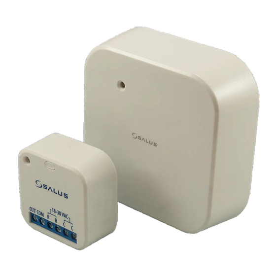
Smart Relay - Low Voltage
N
:
OTE
Additional equipment may be required to address
radio communication issues due to building
construction or materials, or other radio interference.
I
I
NSTALLATION
NSTRUCTIONS
W
B
M
:
ALL
OX
OUNTING
S
M
:
URFACE
OUNTING
W
O
:
IRING
PTIONS
D
C
C
RY
ONTACT
ONNECTIONS
OUT COM R
LOAD OUT
LOAD COMMON
• Power In to terminal R
• Power Return to terminal C
• Load Out to terminal OUT
• Load Common to terminal COM
Quick Start Guide
:
:
18-30 VAC
R
C
C
POWER IN
POWER RETURN
Smart Relay – Low Voltage (SC824ZB)
S
I
AFETY
NSTRUCTIONS
Read these instructions carefully before installing and
using the Smart Relay – Low Voltage and keep this guide
in a safe place for future reference.
• Verify compatibility with your associated
connected home system before installation.
• Follow all instructions provided by your connected
home manufacturer regarding the addition of
devices to your connected home system. An
authorized, qualified installer may be required.
• Follow all applicable codes and regulations in the
municipality where this product is installed.
Salus accepts no responsibility for damage caused by not
following these instructions.
•
Remove the assembly from the carton.
•
Remove the front cover by lifting from the bottom.
•
Position the relay in the desired location.
If anchors are required:
•
Mark the locations of the screws.
•
Drill 3/16" holes.
•
Insert the anchors (provided)
•
Position the relay over the anchors.
•
Secure with 2 mounting screws (provided).
•
Wire relay as desired. See options below. Remove
knockout on bottom side panel if required.
•
Secure cables with the strain relief.
•
Replace the front cover.
•
Remove the assembly from the carton.
•
Remove the front cover by lifting from the bottom.
•
Remove the Relay Retainer by lifting the corners.
•
Wire relay as desired. See options below.
•
Remove white/blank backing from adhesive
(provided).
•
Apply adhesive to bottom half of relay back.
•
Remove red lettered backing from adhesive.
•
Press back of relay onto the surface to be attached.
P
S
C
OWER
WITCH
ONNECTIONS
OUT COM R
LOAD OUT
LOAD COMMON
• Power In to terminal R
• Power Return to terminal C
• Load Out to terminal OUT
• Load Common to the open terminal C
• Add a wire between the open terminal R and COM
Quick Start Guide
:
:
18-30 VAC
R
C
C
POWER IN
POWER RETURN
Advertisement

Related Manuals for Salus SC824ZB

Summary of Contents for Salus SC824ZB
- Page 1 • Follow all applicable codes and regulations in the Additional equipment may be required to address municipality where this product is installed. radio communication issues due to building Salus accepts no responsibility for damage caused by not construction or materials, or other radio interference. following these instructions. NSTALLATION NSTRUCTIONS •...
- Page 2 • To reset to factory default settings, press and hold the Multi Button for 10 seconds. The device will factory reset and return to normal operations. EFAULT TATE OF EMOTELY CCESSED ARAMETERS See the Salus Smart Home app for other options for these parameters. PARAMETER DESCRIPTION Mode Enable/Disable local control of relay state LostConnectionState Relay state when connection is lost.