Table of Contents
Advertisement
Quick Links
Advertisement
Table of Contents

Related Manuals for Supermicro SC506 Series


Summary of Contents for Supermicro SC506 Series
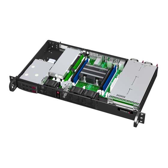
- Page 1 SC506 Chassis Series USER’S MANUAL Revision 1.0...
- Page 2 State of California, USA. The State of California, County of Santa Clara shall be the exclusive venue for the resolution of any such disputes. Supermicro's total liability for all claims will not exceed the price paid for the hardware product.
- Page 3 If you have any questions, please contact our support team at: support@supermicro.com This manual may be periodically updated without notice. Please check the Supermicro website for possible updates to the manual revision level. Warnings Special attention should be given to the following symbols used in this manual.
-
Page 4: Table Of Contents
SC506 Chassis Manual Table of Contents Chapter 1 Introduction 1.1 Overview ..........................7 1.2 Unpacking the System ......................7 1.3 Chassis Features .........................8 Control Panel ........................8 Front Features ........................9 Rear Features ........................9 Chapter 2 Rack Installation 2.1 Overview ..........................10 2.2 Unpacking the System .......................10 2.3 Preparing for Setup ......................10 Choosing a Setup Location ....................10 Rack Precautions ......................10... - Page 5 Preface Drive Carrier Indicators ....................18 System Fans ........................20 Power Supply ........................21 3.4 Installing the Motherboard ....................22 Chassis Standoffs ......................22 Motherboard Installation ....................22 Installing the Motherboard .....................22 Appendix A Cables, Screws, and Other Accessories A.1 Overview ..........................23 A.2 Cables Included with the SC506 Chassis ................23 A-3 Optional Accessories ......................23 Hard Drive Bracket ......................23 Extending Power Cables ....................24...
- Page 6 Super Micro Computer, Inc. 980 Rock Ave. San Jose, CA 95131 U.S.A. Tel: +1 (408) 503-8000 Fax: +1 (408) 503-8008 Email: marketing@supermicro.com (General Information) support@supermicro.com (Technical Support) Website: www.supermicro.com Europe Address: Super Micro Computer B.V. Het Sterrenbeeld 28, 5215 ML...
-
Page 7: Chapter 1 Introduction
Chapter 1 Introduction 1.1 Overview The Supermicro SC506, is an all-purpose chassis for many different applications. It is an excellent chassis platform for data centers, government labs, or business enterprises, for cloud and virtualization, simulation, automation, hosting and storage. In addition to the chassis, several included parts are listed below. -
Page 8: Chassis Features
Supermicro SC506 Chassis User's Manual 1.3 Chassis Features Control Panel The chassis front features a control panel to monitor node function and control power. Figure 1-1. Control Panel Control Panel Features Item Features Description The main power switch applies or removes primary power from the power supply Power button to the server but maintains standby power. -
Page 9: Front Features
Chapter 1: Introduction Front Features The front of the chassis includes 2 hot-swap drive bays and the chassis control panel. Figure 1-2. Chassis Front View Front Chassis Features Item Feature Description Control Panel Described in previous section Drives Two 2.5" SAS3/SATA hot-swap storage drive bays Rear Features The illustration below shows the features on the rear of the chassis. -
Page 10: Chapter 2 Rack Installation
Supermicro SC506 Chassis User's Manual Chapter 2 Rack Installation 2.1 Overview This chapter provides a quick setup to install the chassis into a rack. 2.2 Unpacking the System You should inspect the box the chassis was shipped in, and note if it was damaged in any way. -
Page 11: General Server Precautions
Chapter 6: Rack Installation • In single rack installation, stabilizers should be attached to the rack. • In multiple rack installations, the racks should be coupled together. • Always make sure the rack is stable before extending a component from the rack. •... -
Page 12: Circuit Overloading
Supermicro SC506 Chassis User's Manual Circuit Overloading Consideration should be given to the connection of the equipment to the power supply circuitry and the effect that any possible overloading of circuits might have on overcurrent protection and power supply wiring. Appropriate consideration of equipment nameplate ratings should be used when addressing this concern. -
Page 13: Rack Mounting Instructions
Chapter 6: Rack Installation 2.4 Rack Mounting Instructions This section provides information on installing the SC506 chassis into a rack unit There are a variety of rack units on the market, which may mean the assembly procedure will differ slightly. You should also refer to the installation instructions that came with the rack unit you are using. -
Page 14: Mid-Mount Telco Rack
Supermicro SC506 Chassis User's Manual Mid-Mount Telco Rack The SC506 supports Telco Rack installation. The SC506 chassis compact design allows the chassis to be installed into a Telco rack without the use of rails. Figure 6-2: Installing the Chassis into a Telco Rack Note: figures are for illustrative purposes only. -
Page 15: Standard Rack With A Fixed Rail Kit
Chapter 6: Rack Installation Standard Rack with a Fixed Rail Kit Figure 6-3. Fixed Rails The chassis can be mounted in a rack using a fixed rail kit (optional, MCP-290-50404-0N). Installing the Chassis on Fixed Rails into a Standard Rack Adjust the rails to the appropriate length according to the distance between the front and back of the rack they will be installed on. - Page 16 Supermicro SC506 Chassis User's Manual Attach the rails to the chassis using three screws through the holes in each front bracket to secure a bracket to each side of the chassis. Figure 6-5. Rails Attached to the Chassis Install the chassis on rails into the rack, using three screws through each front bracket and two screws through each rear bracket to secure the rails to the rack.
- Page 17 Chapter 6: Rack Installation Figure 6-8. Installing the Server on Fixed Rails into a Rack Note: Figures are for illustrative purposes only. Servers should always be installed in racks from the bottom up.
-
Page 18: Removing Power
Supermicro SC506 Chassis User's Manual Chapter 3 Maintenance and Component Installation This chapter provides instructions on installing and replacing main system components. To prevent compatibility issues, only use components that match the specifications and/or part numbers given. Installation or replacement of most components require that power first be removed from the system. -
Page 19: Accessing The Chassis
Chapter 3: Maintenance and Component Installation 3.2 Accessing the Chassis The chassis top is removable to allow access to components. Removing the Top Cover 1. Remove the screw from the left, right and top sides of the chassis as shown. 2. -
Page 20: Chassis Components
The SC506 chassis supports two 2.5" storage drives, housed in a drive cage inside the chassis. Note: Enterprise level hard disk drives are recommended for use in Supermicro chassis and servers. For information on recommended HDDs, visit the Supermicro website at http://www. - Page 21 Chapter 3: Maintenance and Component Installation Installing a 2.5" Hard Drive 1. Remove the chassis cover as described in Chapter 3.2. 2. Remove the left chassis handle as shown below. 3. Insert and secure the hard drive(s) to the hard drive cage with screws, included with the hard drive.
-
Page 22: System Fans
Supermicro SC506 Chassis User's Manual System Fans Three hot-swap fans provide cooling. They can be replaced without powering down the system. Fan speed is controlled by a system temperature setting in IPMI. If a fan fails, the remaining fans will ramp up to full speed. The system can continue to run with a failed fan. Replace any failed fan at your earliest convenience with the same type and model. -
Page 23: Power Supply
Power Supply The chassis features redundant power supplies. The power modules can be changed without powering down the system. New units can be ordered directly from Supermicro or authorized distributors. These power supplies are auto-switching capable. This feature enables them to automatically sense the input voltage and operate at a 100-120v or 180-240v. -
Page 24: Installing The Motherboard
Review the documentation that came with your motherboard. Become familiar with component placement, requirements, precautions, and cable connections. The SC506 chassis supports 9.6" x 9.6" Micro ATX motherboards. Refer to the Supermicro Web site or contact Supermicro for assistance. 1. Power down the server, disconnect the power cord from the power supply and remove the cover. -
Page 25: Appendix A Cables, Screws, And Other Accessories
This appendix lists supported cables for your chassis system. It only includes the most commonly used components and configurations. For more compatible cables, refer to the manufacturer of the motherboard you are using and our web site at: www.supermicro.com. A.2 Cables Included with the SC506 Chassis... -
Page 26: Extending Power Cables
Supermicro SC506 Chassis User's Manual Extending Power Cables Although Supermicro chassis are designed with to be efficient and cost-effective, some compatible motherboards have power connectors located in different areas.To use these motherboards you may have to extend the power cables to the mother boards. To do this, use the following chart as a guide. -
Page 27: Chassis Screws
Appendix A: Chassis Cables A-4 Chassis Screws The accessory box includes all the screws needed to setup your chassis. This section lists and describes the most common screws used. Your chassis may not require all the parts listed. HARD DRIVE Flat head Pan head 6-32 x 5 mm... -
Page 28: Appendix B Power Supply Specifications
Supermicro SC506 Chassis User's Manual Appendix B Power Supply Specifications This appendix lists power supply specifications for your chassis system. 80 Plus Gold Level Certified Power Supply 200W MFR Part # PWS-203-1H 100 - 240V Rated AC Voltage 50 - 60Hz... - Page 29 Disclaimer (cont.) The products sold by Supermicro are not intended for and will not be used in life support systems, medical equipment, nuclear facilities or systems, aircraft, aircraft devices, aircraft/emergency communication devices or other critical systems whose failure to perform be reasonably expected to result in significant injury or loss of life or catastrophic property damage.