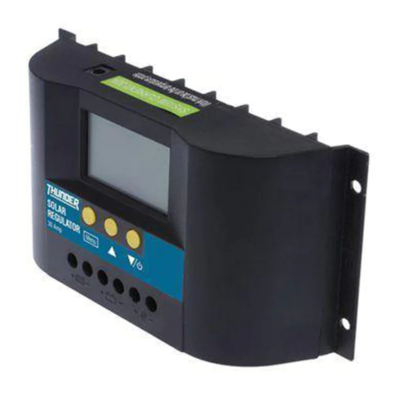
Summary of Contents for Thunder TDR15008
- Page 1 CONGRATULATIONS ON YOUR PURCHASE OF YOUR THUNDER SOLAR REGULATOR! For your personal safety read, understand and follow the information provided in this instruction manual and on the solar regulator.
-
Page 2: Specifications
SPECIFICATIONS RATED CURRENT OPERATING TEMPERATURE -10°C to 60°C RATED VOLTAGE 12V/24V STORAGE TEMPERATURE -30°C to 70°C OPEN CIRCUIT OF SOLAR PANEL <50V DIMENSIONS 90mm(L) x 188mm(W) x 48mm(D) LOW VOLTAGE DISCONNECTION (LVD) 10.7V/21.4V MOUNTING HOLE SPACING 60mm x 178mm FLOAT VOLTAGE 14V/28V WEIGHT 360g... -
Page 3: Installation
INSTALLATION 1. Ensure the regulator is mounted as close to the battery as possible. 2. For best results use at least 6mm² automotive cable. SOLAR PANEL DC LOAD BATTERY 3. Connect the battery positive terminal (B+) and the battery negative terminal (B-) beneath the appropriate + and - symbols in the middle of the regulator. Then connect the solar panel positive and negative leads beneath the appropriate + and - symbols at the left of the regulator. -
Page 4: Description Of Lcd Symbols
DESCRIPTION OF LCD SYMBOLS LCD SYMBOLS Load circuit off No charge going to battery Load circuit on (no current) Bulk charging battery Load circuit on (current being drawn) Float charging battery System is working correctly Battery running low Battery capacity indicator Solar power active Solar not active Load timer control on... - Page 5 VIEW AND PROGRAM SETTINGS The regulator will default to the “battery voltage” screen after correct installation to battery. Use the menu button to switch view to desired screen. Press the menu button to cycle from on view to the next. Battery Voltage Displays current battery voltage, charge status, discharge status and battery capacity.
- Page 6 VIEW AND PROGRAM SETTINGS Accumulated Discharge (Ah) Displays the total amount of discharge, in amp hours, from the regulators load circuit since connection/last reset. To reset to 0, press and hold the menu button (>5 seconds). Low Voltage Disconnect Displays the value for the low voltage disconnection (LVD). Once the battery voltage gets to this level the load circuit will be shut off and show the second screen above.
- Page 7 VIEW AND PROGRAM SETTINGS Load Delay Display shows the delay time for load disconnect. To adjust the load delay, press and hold the menu button (>5 seconds), once the numbers start flashing, use the arrow buttons to change the voltage. To save the settings and return to normal view, press and hold the menu button (>5 seconds).
