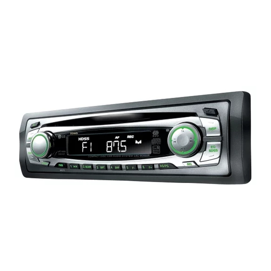
Summary of Contents for LG LAC-M1600
- Page 1 All manuals and user guides at all-guides.com http://biz.lgservice.com DETACHABLE FRONT PANEL CAR CD RECEIVER SERVICE MANUAL CAUTION BEFORE SERVICING THE UNIT, READ THE “SAFETY PRECAUTIONS” IN THIS MANUAL. MODEL : LAC-M3600...
- Page 2 All manuals and user guides at all-guides.com [CONTENTS] ❍ SECTION 1.GENERAL • SERVICING PRECAUTIONS ..........1-2 •...
-
Page 3: Section 1. Summary
All manuals and user guides at all-guides.com SECTION 1. SUMMARY ❏ SERVICING PRECAUTIONS ❶ Always disconnect the power source before: 1) Removing or reinstalling any component, circuit board, module or any other instrument assembly. 2) Disconnecting or reconnecting any instrument electrical plug or other electrical connection. 3) Connecting a test substitute in parallel with an electrolytic capacitor in the instrument. -
Page 4: Esd Precautions
All manuals and user guides at all-guides.com ❏ ESD PRECAUTIONS Electrostatically Sensitive Devices (ESD) Some semiconductor (solid state) devices can be damaged easily by static electricity. Such components commonly are called Electrostatically Sensitive Devices (ESD). Examples of typical ESD devices are integrated circuits and some field-effect transistors and semiconductor chip components. -
Page 5: Specifications
All manuals and user guides at all-guides.com ❏ SPECIFICATIONS 1. GENERAL Power requirements ..........DC12V~15V Ground system . -
Page 6: Section 2. Electrical
All manuals and user guides at all-guides.com SECTION 2. ELECTRICAL ❏ ELECTRICAL TROUBLESHOOTING GUIDE 1. No Power. Any Key power on. Check power supply circuitry. Q930, Q924, Q919, Is power turnd on? Q920, Q921, IC902, pin1 Check loading supply circuitry. DISC loading? Q9001, Q902, Q903, Q904, PN503, IC507, IC506, IC508... - Page 7 All manuals and user guides at all-guides.com 2. LCD light abnormal. Any Key power on. (without DISC) Power supply circuitry defective. Check voltage in the power Do display LCD then light? Q371,Q372,IC403 supply • Reset circuit defective. Is u-com IC906 LCD reset IC901 Surrounding circuit circuit normal?Pin74 defective.
- Page 8 All manuals and user guides at all-guides.com 3. Initial reading is not carried out. Defective Check the Voltage change of Slide motor moves connector CN503 CN503 Pin12 (6.4~6.8V) (With disc) Check the Voltage IC501 Defective IC501 Pin23 (1.4V~1.8V) Spindle motor turns Check the Data transmission Defective connector WAVEFORM #1...
-
Page 9: Open Close
All manuals and user guides at all-guides.com When laser does not light. Is “2.4V~3.4V” applied to pin42 of IC501? ➀ 3.4V ➁ 2.4V) Did pickup return to Is data transferred from Defective MICOM or CN503. innermost circular? MICOM IC ? Does voltage appear at Defective IC501. - Page 10 All manuals and user guides at all-guides.com When laser light. Laser lights Check the signal FOCUS Defective IC501 SEARCH of IC501 Pin25 WAVEFORM #3 Check the signal of IC503 Pin 15, 16 Defective IC501 WAVEFORM #3 Degraded laser diode Defective PICK-UP When SPINDLE motor dose not turn Check the change for SPDO Voltage of...
-
Page 11: Waveforms Of Major Check Point
All manuals and user guides at all-guides.com ❏ WAVEFORMS OF MAJOR CHECK POINT #1. SPINDLE DRIVE AND MOTOR WAVEFORM #2. RF WAVEFORM IC501(21), IC504(12) during TOC reading IC501(45), IC501(49) during TOC reading #3. FOCUS DRIVE AND MOTOR WAVEFORM IC501(25), IC503(15) •... -
Page 12: Internal Block Diagram Of Ics
All manuals and user guides at all-guides.com ❏ INTERNAL BLOCK DIAGRAM of ICs AV_CAR 1) Micom Port Assignment - 2-7 -... - Page 13 All manuals and user guides at all-guides.com 2) Pin Descriptions - 2-8 -...
- Page 14 All manuals and user guides at all-guides.com - 2-9 -...
-
Page 15: Block Diagram
All manuals and user guides at all-guides.com BD3805F 1) BLOCK DIAGRAM - 2-10 -... - Page 16 All manuals and user guides at all-guides.com MN6627933CN(DSP) 1) Connection Diagram - 2-11 -...
- Page 17 All manuals and user guides at all-guides.com TA8275HQ 1) Block Diagram - 2-12 -...
- Page 18 All manuals and user guides at all-guides.com upd78f0546(Micom) 1) Block Diagram - 2-13 -...
- Page 19 All manuals and user guides at all-guides.com 2) Pin lay out - 2-14 -...
- Page 20 All manuals and user guides at all-guides.com 3) Pin Function PIN NAME Function Positive power supply except for ports ( except P20-P27 and P121-P124) and AD converter Ground potential except for ports (except P20-P27 and P121-P124) and AD converter EVDD Positive power supply for ports (expect p20-p27 and p121-p124) EVSS Ground potential for ports (except p20-p27 and p121-p124)
- Page 21 All manuals and user guides at all-guides.com PIN NAME Function P62/EXSCL0 I/O port (N-ch open drain) External clock input for serial interface (IIC0) I/O port (N-ch open drain) P64-P67 I/O ports P70-P77 I/O ports /KR0-KR7 Key interrupt input P120 I/O port /INTP0 External interrupt request input with specifiable vaild edges /EXLVI...
- Page 22 All manuals and user guides at all-guides.com ❏ BLOCK DIAGRAM 2-17 2-18...
-
Page 23: Main Schematic Diagram
All manuals and user guides at all-guides.com ❏ SCHEMATIC DIAGRAMS • MAIN SCHEMATIC DIAGRAM 2-19 2-20... - Page 24 All manuals and user guides at all-guides.com • MAIN-2 SCHEMATIC DIAGRAM 2-21 2-22...
-
Page 25: Front Schematic Diagram
All manuals and user guides at all-guides.com • FRONT SCHEMATIC DIAGRAM 2-23 2-24... - Page 26 All manuals and user guides at all-guides.com • CD SCHEMATIC DIAGRAM 2-25 2-26...
-
Page 27: Printed Circuit Board Diagrams
All manuals and user guides at all-guides.com ❏ PRINTED CIRCUIT BOARD DIAGRAMS • MAIN P.C. BOARD DIAGRAM 2-27 2-28... - Page 28 All manuals and user guides at all-guides.com • FRONT/TRIM P.C. BOARD DIAGRAM • LED P.C. BOARD 2-29 2-30...
- Page 29 All manuals and user guides at all-guides.com • CD P.C. BOARD 2-31 2-32...
-
Page 30: Section 3. Exploded Views
All manuals and user guides at all-guides.com SECTION 3. EXPLODED VIEWS ❏ CABINET AND MAIN FRAME SECTION *Accessory... - Page 31 All manuals and user guides at all-guides.com ❏ MECHANISM (PICK-UP)


