
Summary of Contents for Nuvo Navigator Lift 150 Single
- Page 1 Installation Instructions Part 2 – Pendant system [EN] Navigator Lift ™ 150 Single, Navigator Lift ™ 250 Single, ™ ™ Navigator Lift 150 Dual, Navigator Lift XL 250 Dual...
- Page 2 • These Installation Instructions are intended for trained service technicians. qualification requirements • The Nuvo pendant system may only be installed by Nuvo service technicians or authorised service personnel trained by Nuvo. Inspections to be performed • The load bearing capacity of the ceiling or the wall must be checked by a structural prior to installation analyst and confirmed by means of an acceptance certificate.
- Page 3 How to contact us Nuvo Surgical • 1565 West 12th Street • Erie, PA 16501 • USA Phone: +1 (800) 663-1152 (USA and CANADA) Phone: +1 (814) 899-4220 (INTERNATIONAL) © Nuvo Surgical, 2019 1568911, Edition 2019-04, Version 0 Visit us on the Internet www.nuvosurgical.com...
-
Page 4: Table Of Contents
Overview of the optional accessories Scope of delivery of the optional accessories Further optional accessories 2 Safety Instructions Approved Nuvo products Combination with products of other manufacturers Structure of the safety instructions 2.3.1 Warnings of risk of injury 2.3.2 Warnings of damage to property 2.3.3 Indication of additional information... - Page 5 7 Pre-Assembly: Mounting an Extended Ceiling Tube Components described in this chapter Mounting an extended ceiling tube 7.2.1 Mounting a ceiling tube 7.2.2 Mounting the strain relieving mechanism in the ceiling tube 7.2.3 Subsequently mounting the earthing cable to the ceiling tube 8 Mounting the Ceiling Tube to the Threaded Bolts of the Interface Plate Components described in this chapter Mounting a ceiling tube...
- Page 6 11.10 Connecting the earthing cables to the motor arm Single arm, with Navigator M6 11.11 Routing the supply cables and hoses through the motor arm Single arm, with Navigator M6 12 Connecting the Supply Cables and Hoses 12.1 Safety Instructions 12.2 Installing gas supply hoses and exhaust air ducts 12.3...
- Page 7 18 Technical Data 19 Electromagnetic Compatibility (EMC) Information 19.1 Guidelines and manufacturer’s declarations 19.1.1 Electromagnetic emissions 19.1.2 Electromagnetic immunity 19.1.3 Test specifications 20 Approved Nuvo Products 21 Optional Accessories 22 Possible Combination with Third-Party Products Notes 1568911, Edition 2019-04, Version 0...
-
Page 8: Versions, Scope Of Delivery And Installation References
Versions, Scope of Delivery and Installation References Overview of the pendant system Figure 1: Scope of delivery of the motor arm, ™ Navigator Lift 150 / 250 Single arm 1568911, Edition 2019-04, Version 0... -
Page 9: Scope Of Delivery Of The Motor Arm, Navigator Lift ™ 150 / 250 Single Arm
Versions, Scope of Delivery and Installation References See “Figure 1: page 8” Interface plate (Single / Duo) – pre-assembled Intermediate ceiling – installed by the customer on site Scope of delivery of the motor arm, Navigator Lift 150 / 250 ™... -
Page 10: Overview Of The Pendant System
Versions, Scope of Delivery and Installation References Overview of the pendant system Figure 2: Scope of delivery of the extension ™ arm with motor arm, Navigator Lift 150 Dual 1568911, Edition 2019-04, Version 0... -
Page 11: Scope Of Delivery Of The Extension Arm With Motor Arm
Versions, Scope of Delivery and Installation References See “Figure 2: page 10” Interface plate (Single / Duo) – pre-assembled Intermediate ceiling – installed by the customer on site Scope of delivery of the extension arm with motor arm, Navigator Lift ™... -
Page 12: Overview Of The Pendant System
Versions, Scope of Delivery and Installation References Overview of the pendant system Figure 3: Scope of delivery of the XL exten- ™ sion arm with motor arm, Navigator Lift / 250 XL Dual arm 1568911, Edition 2019-04, Version 0... -
Page 13: Scope Of Delivery Of The Xl Extension Arm With Motor Arm
Versions, Scope of Delivery and Installation References See “Figure 3: page 12” Interface plate (Single / Duo) – pre-assembled Intermediate ceiling – installed by the customer on site Scope of delivery of the XL extension arm with motor arm, Navigator Lift ™... -
Page 14: Overview Of The Optional Accessories
Versions, Scope of Delivery and Installation References Overview of the optional accessories Figure 4: Scope of delivery of the optional accessories 1568911, Edition 2019-04, Version 0... -
Page 15: Scope Of Delivery Of The Optional Accessories
Versions, Scope of Delivery and Installation References See “Figure 4: page 14” Upon delivery of the system from the factory the following optional accessories are al- ready pre-assembled: Scope of delivery of the optional accessories Indirect extension arm lighting – for extension arm lengths 800, 1000, 1200mm –... -
Page 16: Safety Instructions
Approved Nuvo products The following Nuvo products are approved for use on the pendant system: • Nuvo products as described in Chapter 20, “Approved Nuvo Products”, on page 92 Combination with products of other manufacturers Observe the Installation Instructions •... -
Page 17: Supplementary Symbols Used In The Safety Instructions
Environmentally friendly disposal: warns of damage to the environment caused by improp- er disposal of the pendant system (must not be disposed of as normal household waste). CE mark: Nuvo declares that the products comply with the relevant regulations set forth in the applicable European Directives. -
Page 18: Intended Purpose
Safety Instructions Atmospheric pressure: indicates the permissible atmospheric pressure values in a range from 500hPa to 1060hPa for transport and storage. Relative humidity: indicates the permissible humidity values in a range from 10% to 75% for transport and storage. Ambient temperature: indicates the permissible ambient temperature values in a range from -25°C to 70°C for transport and storage. -
Page 19: Ambient Conditions
Safety Instructions Ambient conditions 2.7.1 Ambient conditions for storage and transport The following conditions apply to storage: • Ambient temperature: -25 °C to 70 °C • Relative humidity: 10 % to 75 % • Atmospheric pressure: 500 hPa to 1,060 hPa Store only in indoor rooms. -
Page 20: Retrofit To An Already Installed Ceiling Mount
Safety Instructions Retrofit to an already installed ceiling mount WARNING Risk of the ceiling mount dropping In the case of retrofits to an already installed ceiling mount the fixing ele- ments used must be inspected by a structural analyst and approved for the new pendant system: •... -
Page 21: Proper Use Of Oxygen
• only genuine spare parts or accessories and those defined and approved by Nuvo are used. The use of other parts may involve unknown risks and must be avoided in all cases. • inspections and maintenance are carried out at the specified time inter- vals. -
Page 22: Further Applicable Installation Instructions
Further Applicable Installation Instructions Figure 6: Overview of the structure of these Installation The Installation Instructions for the entire ceiling support system consist Instructions of separate documents. For this reason, these Installation Instructions are only valid and complete if all the documents are available at the place of installation. -
Page 23: Installation Equipment Required
Installation Equipment Required • Lifting device or forklift with a permitted payload of at least 250kg Alternatively, a hoisting winch with an admissible payload of at least 250kg can be used if space is limited: – Check that the pendant system is sufficiently secured before lifting it. –... -
Page 24: Load Data
Load Data Load data of the Single version Figure 7: Load data of the Single version ™ ™ (Navigator with Navigator Lift 250) (See "Figure 7") The data required for calculating the ceiling load is indicated in the tables below. When mounting the pendant system to the Intermediate ceiling set, the vertical weight force of the Intermediate ceiling set (the values correspond to the maximum load) must be added to the corresponding values of the pendant system in order to determine the ceiling load. -
Page 25: Mounting Threaded Bolts To The Interface Plate
Mounting Threaded Bolts to the Interface Plate Mounting situation: Mounting the interface plate Figure 9: Cutting and installing the threaded bolts for the Sin- to the raw ceiling without intermediate ceiling gle / Duo interface plate on the raw ceiling 6.1.1 Versions (See "Figure 9") The following Figures illustrate the interface plate... -
Page 26: Mounting The Upper Insulations To The Threaded Bolts
Mounting Threaded Bolts to the Interface Plate 6.1.4 Mounting the upper insulations to the threaded bolts Figure 10: Mounting the upper insulations to the threaded bolts (See "Figure 10") The 6 (Single version) or 12 (Duo version) hexagonal nuts M16② must be mounted to the threaded bolts M16①... -
Page 27: Mounting Situation: Interface Plate On The Intermediate Ceiling Mount
To determine the length LG of the threaded bolts①: LG=H +135mm (min. 205mm / max. 245mm) • Please contact Nuvo if you have any doubt. Slightly deburr the 6/12 threaded bolts M16 x 330mm① in order to ensure maximum thread engagement into the interface plate Continue the installation as described in Chapter 6.2.3 on Page 28. -
Page 28: Mounting The Threaded Bolts To The Single / Duo Interface Plate
Mounting Threaded Bolts to the Interface Plate 6.2.3 Mounting the threaded bolts to the Single / Duo interface Figure 12: Mounting the upper insulations to the threaded plate bolts (See "Figure 12") Screw 1 hexagonal nut M16② each onto the 6/12 threaded bolts M16③... -
Page 29: Mounting The Upper Insulations To The Threaded Bolts
Mounting Threaded Bolts to the Interface Plate 6.2.4 Mounting the upper insulations to the threaded bolts Figure 13: Mounting the upper insulations to the threaded bolts (See "Figure 13") For each threaded bolt M16① screw a hexagonal nut M16② onto the threaded bolts M16①. -
Page 30: Mounting Situation: Interface Plate On The Intermediate Ceiling Mount
Mounting Threaded Bolts to the Interface Plate Mounting situation: Interface plate on the inter- Figure 14: Mounting the threaded bolts mediate ceiling mount 6.3.1 Versions (See "Figure 14") The following Figures illustrate the interface plate , Single (round shape), for installing the motor arm and motor arm with extension arm versions. -
Page 31: Mounting The Upper Insulations To The Threaded Bolts
Mounting Threaded Bolts to the Interface Plate 6.3.3 Mounting the upper insulations to the threaded bolts Figure 15: Mounting the upper insulations to the threaded bolts (See "Figure 15") The 6 (Single version) or 12 (Duo version) hexagonal nuts M16② must be mounted to the threaded bolts M16 x 330mm①... -
Page 32: Pre-Assembly: Mounting An Extended Ceiling Tube
Pre-Assembly: Mounting an Extended Ceiling Tube Components described in this chapter Figure 16: Components described in this chapter (See "Figure 16") • The ceiling tube illustrated in the Figure is mounted to the motor or extension arm with motor arm or XL extension arm with motor arm •... -
Page 33: Mounting An Extended Ceiling Tube
Pre-Assembly: Mounting an Extended Ceiling Tube Mounting an extended ceiling tube Figure 17: Mounting a ceiling tube 7.2.1 Mounting a ceiling tube (See "Figure 17") The Figure shows the ceiling tube for the motor arm or extension arm with motor arm with 8 Allen cylinder screws M10 x 25mm①... -
Page 34: Mounting The Strain Relieving Mechanism In The Ceiling Tube
Pre-Assembly: Mounting an Extended Ceiling Tube 7.2.2 Mounting the strain relieving mechanism in the ceiling Figure 18: Mounting the strain relieving mechanism in the ceil- tube ing tube (See "Figure 18") The Figure shows the ceiling tube with 8 Allen cylinder screws M10 x 25mm①... -
Page 35: Subsequently Mounting The Earthing Cable To The Ceiling Tube
Pre-Assembly: Mounting an Extended Ceiling Tube 7.2.3 Subsequently mounting the earthing cable to the ceiling Figure 19: Subsequently mounting the earthing cable to the tube ceiling tube (See "Figure 19") The system is delivered with the earthing cable pre-assembled! Fit 1 lock washer S4②/④ each above and below the ring cable lug③... -
Page 36: Mounting The Ceiling Tube To The Threaded Bolts Of The Interface Plate
Mounting the Ceiling Tube to the Threaded Bolts of the Interface Plate Components described in this chapter Figure 20: Components described in this chapter (See "Figure 20") • The motor arm or the extension arm with motor arm or the XL extension arm with motor arm illustrated in the Figure is mounted to the threaded bolts of the interface plate... -
Page 37: Mounting A Ceiling Tube
Mounting the Ceiling Tube to the Threaded Bolts of the Interface Plate Mounting a ceiling tube Figure 21: Mounting a ceiling tube (See "Figure 21") The Figure only shows a simplified representation of the flange⑥ with ceiling tube to be mounted to the threaded bolts. Further components pre-assembled to the flange⑥, such as the motor arm, extension arm, cables, etc. -
Page 38: Aligning The Motor Arm / Extension Arm With The Interface Plate, Single
Mounting the Ceiling Tube to the Threaded Bolts of the Interface Plate Aligning the motor arm / extension arm with the Figure 22: Aligning the motor arm / extension arm with the interface plate, Single interface plate, Single (See "Figure 22") The Figure only shows a simplified representation of the flange③... - Page 39 Mounting the Ceiling Tube to the Threaded Bolts of the Interface Plate Figure 23: Checking the horizontal alignment of the motor arm (See "Figure 23") / extension arm Check the horizontal alignment of the motor arm / extension arm. • Place the digital spirit level at right angles onto the motor arm or extension arm (near the flange③).
-
Page 40: Aligning The Motor Arm / Extension Arm With The Interface Plate, Duo
Mounting the Ceiling Tube to the Threaded Bolts of the Interface Plate Aligning the motor arm / extension arm with the Figure 24: Aligning the motor arm / extension arm with the interface plate, Duo interface plate, Duo (See "Figure 24") The Figure only shows a simplified representation of the flange③... - Page 41 Mounting the Ceiling Tube to the Threaded Bolts of the Interface Plate Figure 25: Checking the horizontal alignment of the motor arm (See "Figure 25") / extension arm Check the horizontal alignment of the motor arm / extension arm. • Place the digital spirit level at right angles onto the motor arm or extension arm (near the flange③).
-
Page 42: Mounting The Console Tube To The Motor Arm
Mounting the Console Tube to the Motor Arm Components described in this chapter Figure 26: Components described in this chapter (See "Figure 26") • The Drop tube illustrated in the Figure is mounted to the motor or extension arm with motor arm or XL extension arm with motor arm •... -
Page 43: Mounting The Console Tube To The Motor Arm
Mounting the Console Tube to the Motor Arm Mounting the console tube to the motor arm Figure 27: Mounting the console tube to the motor arm (See "Figure 27") The Figure shows a magnified sectional view of the extension arm with- out its top side. -
Page 44: Mounting Optional Accessories
Mounting Optional Accessories 10.1 Mounting the Extension Arm Lighting (for Retro- Figure 28: Mounting the extension arm lighting fit only) (See "Figure 28") Upon delivery of the system from the factory the following optional accessories are pre-assembled: The Figure shows the extension arm with motor arm . -
Page 45: Mounting The Brake Indicators (For Retrofit Only)
Mounting Optional Accessories 10.2 Mounting the brake indicators (for retrofit only) Figure 29: Mounting the brake indicators (See "Figure 29") Upon delivery of the system from the factory the following optional accessories are pre-assembled: The Figure shows the extension arm with motor arm . -
Page 46: Mounting Cables
Mounting Cables 11.1 Versions The insertion of the cables is described using the example of the extension arm with motor version. The installation procedure for the XL extension arm with motor arm version is identical. 11.2 Safety instructions WARNING Electric shock hazard Power cables may have been laid in the pendant system. -
Page 47: Swinging Out / Retracting The Electronic Unit
Mounting Cables 11.3 Swinging out / retracting the electronic unit Figure 30: Swinging out / retracting the electronic unit The electronic unit can be swung out for easier cable installation. The procedure is identical for all versions. The Figure shows a simplified representation with only the flange with ceiling tube. -
Page 48: Connecting Cables To The Extension Arm With Motor Arm Dual Arm, With Navigator M6
11.4 Connecting cables to the extension arm with motor arm Dual arm, with Navigator M6 The cables are pre-assembled by Nuvo. The instructions in the paragraphs below only re- fer to the connection or replacement of cables. 1. Observe the safety instructions in Chapter 11.2 on Page 46. - Page 49 Mounting Cables Figure 31: Connecting the cables to the extension arm with motor arm Dual arm, with Navigator M6 Table 02: Cable assignment: extension arm with motor arm Dual arm, with Navigator M6 No. in From Designation Length Remark Fig. 31 [mm] ②...
-
Page 50: Connecting Optional Accessories To The Extension Arm With Motor Arm Dual Arm, With Navigator M6
11.5 Connecting optional accessories to the extension arm with motor arm Dual arm, with Navigator M6 The cables are pre-assembled by Nuvo. The instructions in the paragraphs below only re- fer to the connection or replacement of cables. 1. Observe the safety instructions in Chapter 11.2 on Page 46. - Page 51 Mounting Cables Figure 32: Connecting optional accessories to the extension arm with motor arm Dual arm, with Navigator M6 Table 03: Cable assignment: extension arm with motor arm Dual arm, with Navigator M6 – optional accessories No. in From Designation Length Remark Fig.
-
Page 52: Connecting Earthing Cables To The Extension Arm With Motor Arm Dual Arm, With Navigator M6
Mounting Cables 11.6 Connecting earthing cables to the extension arm with motor arm Dual arm, with Navigator M6 (See "Figure 33“) The earthing cables are pre-assembled in the extension arm and the motor arm and must be laid and connected in the direction of the arrow. 1. - Page 53 Mounting Cables Figure 33: Connecting the earthing cables to the extension arm with motor arm Dual arm, with Navigator M6 Figure 34: Routing the supply cables and hoses through the extension arm with motor arm Dual arm, with Navigator M6 1568911, Edition 2019-04, Version 0...
-
Page 54: Connecting The Cables To The Motor Arm Single Arm, With Navigator M6
11.8 Connecting the cables to the motor arm Single arm, with Navigator M6 The cables are pre-assembled by Nuvo. The instructions in the paragraphs below only re- fer to the connection or replacement of cables. 1. Observe the safety instructions in Chapter 11.2 on Page 46. - Page 55 Mounting Cables Figure 35: Connecting the cables to the motor arm Single arm, with Navigator M6 Table 04: Cable assignment: motor arm Single arm, with Navigator M6 No. in From Designation Length Remark Fig. 35 [mm] ③ Main board DC/DC converter Power board / DC converter Power ca- Pre-assembled ④...
-
Page 56: Connecting The Optional Accessories To The Motor Arm Single Arm, With Navigator M6
11.9 Connecting the optional accessories to the motor arm Single arm, with Navigator M6 The cables are pre-assembled by Nuvo. The instructions in the paragraphs below only re- fer to the connection or replacement of cables. 1. Observe the safety instructions in Chapter 11.2 on Page 46. - Page 57 Mounting Cables Figure 36: Connecting the optional accessories to the motor arm Single arm, with Navigator M6 Table 05: Cable assignment: motor arm Single arm, with Navigator M6 – optional accessories No. in From Designation Length Remark Fig. 36 [mm] ②...
-
Page 58: Connecting The Earthing Cables To The Motor Arm Single Arm, With Navigator M6
Mounting Cables 11.10 Connecting the earthing cables to the motor arm Single arm, with Navigator M6 (See "Figure 37“) The earthing cables are pre-assembled in the motor arm and must be laid and connected in the direction of the arrow. 1. - Page 59 Mounting Cables Figure 37: Connecting the earthing cables to the motor arm Single arm, with Navigator M6 Figure 38: Routing the supply cables and hoses through the motor arm Single arm, with Navigator M6 1568911, Edition 2019-04, Version 0...
-
Page 60: Connecting The Supply Cables And Hoses
Connecting the Supply Cables and Hoses 12.1 Safety Instructions WARNING Qualification of installation personnel The electrical connection of the pendant system and the Navigator M6 may only be performed by a qualified electrician: • Observe the safety instructions set out in the Installation Instructions Part 1 –... -
Page 61: Installing Gas Supply Hoses And Exhaust Air Ducts
Connecting the Supply Cables and Hoses 12.2 Installing gas supply hoses and exhaust air Figure 39: Installing gas supply hoses and exhaust air ducts ducts (See "Figure 39") Observe the safety instructions in Chapter 12.1 on Page 60. NOTE – Make sure that the gas types are correctly assigned •... -
Page 62: Connecting The Earthing Cables
Connecting the Supply Cables and Hoses 12.3 Connecting the earthing cables Figure 40: Connecting the earthing cables (See "Figure 40") The Figure shows a simplified illustration of the interface plate without extension arm and cables, etc. Observe the safety instructions in Chapter 12.1 on Page 60. Cut all green/yellow earthing cables (2.5mm²... -
Page 63: Replacing The Fuse
Connecting the Supply Cables and Hoses 12.4.2 Replacing the fuse Abbildung 42: Replacing the fuse (See "Figure 42") If the fuse blows, it can be replaced. Observe the safety instructions in Chapter 12.1 on Page 60. If required, swing the electronic unit out of the motor arm as de- scribed in Chapter 11.3 on Page 47. -
Page 64: Connecting Power Cables
Connecting the Supply Cables and Hoses 12.4.3 Connecting power cables Figure 43: Connecting power cables (See "Figure 43") The Figure shows a simplified illustration of the interface plate without extension arm and cables, etc. Observe the safety instructions in Chapter 12.1 on Page 60. Route all power cables through the strain relieving mechanism①... -
Page 65: Inspections
Inspections 13.1 Gas inspection (only Navigator M6) Gas outlets and marking in accordance with DIN EN ISO 9170-1 or DIN EN ISO 9170-2 Leakage in accordance with DIN EN ISO 11197 Congestion in accordance with DIN EN ISO 7396-1 or DIN EN ISO 7396-2 Solid contamination in accordance with DIN EN ISO 7396-1 or DIN EN ISO 7396-2 Gas type in accordance with DIN EN ISO 7396-1 or DIN EN ISO 7396-2 13.2 Mechanical collision test... -
Page 66: Mounting The Canopy, Cover Caps And The Cover Panels
Mounting the Canopy, Cover Caps and the Cover Panels 14.1 Mounting a Single / Duo canopy Figure 44: Preparing the installation of the canopy 14.1.1 Preparing the installation of the canopy (See "Figure 44") The Figure shows a simplified illustration of the interface plate without ca- bles and without the extension arm or motor arm. -
Page 67: Mounting The Single Canopy
Mounting the Canopy, Cover Caps and the Cover Panels 14.2 Mounting the Single canopy Figure 46: Preparing the installation of the canopy 14.2.1 Preparing the installation of the canopy (See "Figure 46") The Figure shows a simplified illustration of the interface plate without ca- bles and without the extension arm or motor arm. -
Page 68: Mounting/Dismantling The Cover Caps To/From The Extension Arm
Mounting the Canopy, Cover Caps and the Cover Panels 14.3 Mounting/dismantling the cover caps to/from the Figure 48: Mounting the cover caps extension arm 14.3.1 Mounting the cover caps (See "Figure 48") The Figure shows the extension arm with motor arm . -
Page 69: Mounting The Cover Plates To The Motor Arm
Mounting the Canopy, Cover Caps and the Cover Panels 14.4 Mounting the cover plates to the motor arm Figure 50: Mounting the cover plates to the motor arm (See "Figure 50") The Figure shows the motor arm . The installation procedure for the extension arm with motor arm or the XL extension arm with motor arm version is identical. -
Page 70: Mounting The Rear Side Panels To The Motor Arm
Mounting the Canopy, Cover Caps and the Cover Panels 14.5 Mounting the rear side panels to the motor arm Figure 51: Mounting the rear side panels to the motor arm (See "Figure 51") The Figure shows the motor arm . The installation procedure for the extension arm with motor arm or the XL extension arm with motor arm version is identical. -
Page 71: Mounting The Front Side Panels To The Motor Arm
Mounting the Canopy, Cover Caps and the Cover Panels 14.7 Mounting the front side panels to the motor arm Figure 53: Mounting the front side panels to the motor arm (See "Figure 53") The Figure shows the motor arm . The installation procedure for the extension arm with motor arm or the XL extension arm with motor arm version is identical. -
Page 72: Adjustments
Adjustments 15.1 General safety instructions WARNING Electric shock hazard Electrical supply cables are laid in the pendant system. Contact with energised components presents a danger to life from electric shock. Disconnect the appliance from the mains before any adjustment work: •... -
Page 73: Adjusting The Vertical Lift On The Motor Arm
Adjustments 15.3 Adjusting the vertical lift on the motor arm Figure 56: Opening the bottom rear cover (See "Figure 56") The simplified representation illustrates the extension arm and motor arm without the cables mounted. The adjustment is identical for all versions. The motor arm has a vertical lift of + 20 degrees in the upwards direction –... -
Page 74: Adjusting The Vertical Lift
Adjustments 15.3.3 Adjusting the vertical lift Figure 57: Adjusting the vertical lift and shutting the bottom rear cover (See "Figure 57") Tool to be used Use an Allen key (size 2.5). Unscrew 2 Allen countersunk screws M4 x 6mm⑦ – ISO 7380 – 10.9. -
Page 75: Correcting The Vertical Alignment Of The Navigator M6
Adjustments 15.4 Correcting the vertical alignment of the Naviga- Figure 58: Correcting the vertical alignment of the Navigator tor M6 (See "Figure 58") After mounting an end device (e.g. medical device, etc.) it may be neces- sary to vertically align this end device. 15.4.1 Opening the bottom rear cover (See "Figure 58") Tool to be used... -
Page 76: Condition Of The Swivel Stop On The Extension Arm And The Motor Arm Supplied
Adjustments 15.5 Condition of the swivel stop on the extension Figure 59: Extension arm and motor arm with pre-assembled arm and the motor arm supplied swivel stop 15.5.1 Extension arm and motor arm with pre-assembled swivel stop (See "Figure 59") The system is supplied by default with the 2 ball stops②... -
Page 77: Adjusting The Swivel Stop On The Extension Arm And Motor Arm
For the motor arm use 1 setscrew M16 and 2 ball stops Ø 12.7mm. 15.6.2 Tool to be used A magnetic pin is required in order to offset the ball stop. A telescopic magnet pick-up tool set can be ordered from Nuvo. 1568911, Edition 2019-04, Version 0... -
Page 78: Mounting The Swivel Stop
Adjustments 15.6.3 Mounting the swivel stop Figure 61: Mounting the swivel stop (See "Figure 61") Follow the general safety instructions prescribed in Chapter 15.1 on Page 72. The assignment and size of the setscrew① and the ball stop③ for the different pendant system versions are described in Chapter 15.6.1, “Versions”, on page 77. -
Page 79: Dismantling The Swivel Stop
Adjustments 15.6.4 Dismantling the swivel stop Figure 62: Dismantling the swivel stop (See "Figure 62") Follow the general safety instructions prescribed in Chapter 15.1 on Page 72. The assignment and size of the setscrew① and the ball stop③ for the different pendant system versions are described in Chapter 15.6.1, “Versions”, on page 77. -
Page 80: Initial And Repeated Commissioning And Handover
Initial and Repeated Commissioning and Handover Initial commissioning 1. The pendant system must be properly installed. Instructions for installation are in- cluded in the scope of delivery of the product. 2. For commissioning following installation, proper initial commissioning must be car- ried out for the entire pendant system. -
Page 81: Technical Description
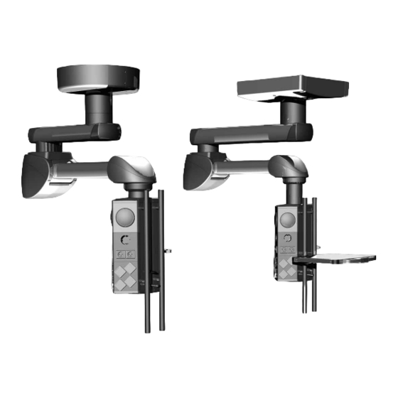
Technical Description 17.1 Motor arm, Navigator Lift 150 / 250 Single arm with Navigator M6 ™ This section presents configuration examples for the Navigator Lift ™ 150 / 250 product family. The schematic representation differs from the individually configured Navigator Lift ™... - Page 82 Technical Description 17.2 Extension arm with motor arm, Navigator Lift ™ 150 Dual arm with Navigator M6 ™ This section presents configuration examples for the Navigator Lift 150 / 250 product family. The schematic representation differs from the ™ individually configured Navigator Lift 150 / 250.
- Page 83 Technical Description 17.3 XL extension arm with motor arm, MediLift ® XL 250 Dual arm with Navigator M6 ™ This subchapter presents configuration examples for the Navigator Lift 250 product family. The schematic representation differs from the ™ individually configured Navigator Lift 150 / 250.
-
Page 84: Technical Data
Technical Data Modes of operation • The pendant systems Navigator Lift ™ 150 Single, Navigator Lift ™ 250 Single, ™ ™ Navigator Lift 150 Dual, Navigator Lift XL 250 Dual are suitable for continuous operation. Duty cycle of the • The maximum duty cycle of the height adjustment mechanism on the motor arm must height adjustment mechanism not exceed 3 minutes:... - Page 85 Technical Data Maximum loading capacity Motor arm 150 (1015mm long) .................150kg on the pendant system Motor arm 250 (1015mm long) .................250kg Extension arm, 600mm, with motor arm 150 (1015mm long) ........150kg Extension arm, 800mm, with motor arm 150 (1015mm long) ........150kg Extension arm, 1000mm, with motor arm 150 (1015mm long) ........150kg Extension arm, 1200mm, with motor arm 150 (1015mm long) ........140kg XL extension arm, 600mm, with motor arm 250 (1015mm long) ......250kg...
- Page 86 – The combination of any other Nuvo product with the pendant system must be approved by Nuvo Surgical. If applicable, the conformity assessment must be repeated. Read the Installation Instructions •...
-
Page 87: Electromagnetic Compatibility (Emc) Information
Electromagnetic Compatibility (EMC) Information 19.1 Guidelines and manufacturer’s declarations 19.1.1 Electromagnetic emissions The Navigator Lift ™ 150 / 250 is intended for use in the ELECTROMAGNETIC ENVIRON- MENT specified below. The customer or the user of the Navigator Lift ™ 150 / 250 must en- sure that it is used in such an environment. -
Page 88: Electromagnetic Immunity
Electromagnetic Compatibility (EMC) Information 19.1.2 Electromagnetic immunity The Navigator Lift ™ 150 / 250 is intended for use in the ELECTROMAGNETIC environ- ment specified below. The customer or the user of the Navigator Lift ™ 150 / 250 should en- sure that it is used in such an environment. - Page 89 Electromagnetic Compatibility (EMC) Information Cont. The Navigator Lift ™ 150 / 250 is intended for use in the ELECTROMAGNETIC environ- ment specified below. The customer or the user of the Navigator Lift ™ 150 / 250 should en- sure that it is used in such an environment. Interference immunity test Test level in accordance with IEC 60601 Compliance level...
-
Page 90: Test Specifications
Electromagnetic Compatibility (EMC) Information 19.1.3 Test specifications Test specifications for the INTERFERENCE IMMUNITY of ENCLOSURES against high- frequency wireless communication facilities Test frequency Frequency band Radio service Modulation Maximum Distance IMMUNITY TEST power LEVEL 380 to 390 TETRA 400 Pulse modulation 18Hz 430 to 470 GMRS 460,... - Page 91 Electromagnetic Compatibility (EMC) Information WARNING Do not operate this device immediately next to or together with other devices stacked on top of each other because this could result in improper operation. If operation in the described manner is unavoidable, this device and all other devices should be monitored in order to ensure proper opera- tion."...
-
Page 92: Approved Nuvo Products
Possible Combination with Third-Party Products Approved third-party products with CE mark For more detailed information on the requirements for the interface towards the pendant system please contact Nuvo customer service so as to prevent damage to persons or property: •... -
Page 93: Notes
Notes 1568911, Edition 2019-04, Version 0... - Page 94 Notes 1568911, Edition 2019-04, Version 0...
- Page 95 Notes 1568911, Edition 2019-04, Version 0...