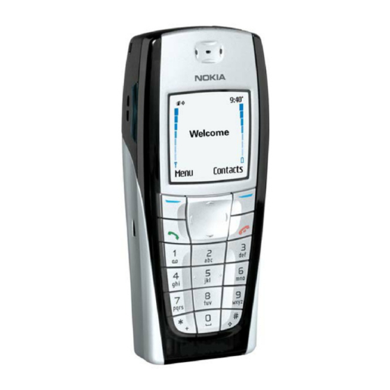
Nokia RH-27 Series Troubleshooting Manual
Gps
Hide thumbs
Also See for RH-27 Series:
- Technical documentation manual (60 pages) ,
- Troubleshooting manual (10 pages) ,
- Troubleshooting instructions (6 pages)
Summary of Contents for Nokia RH-27 Series
- Page 1 CCS Technical Documentation RH-27 Series Transceivers Troubleshooting - GPS ©2003 Nokia Corporation Issue 1 11/2003 Confidential...
-
Page 2: Table Of Contents
Page No Troubleshooting - Global Positioning System (GPS) Engine........3 GPS General Block Diagram ..................3 GPS RF Schematic ......................3 GPS Testing .........................4 GPS RF Probing Setup ....................7 GPS RF Probing Measurements................8 ©2003 Nokia Corporation Page 2 Confidential Issue 1 11/2003... -
Page 3: Troubleshooting - Global Positioning System (Gps) Engine
TRF5101 16.368MHz GPS RF Cellular Baseband GPS RF Schematic GPS RF Chip (N001) Filter 1 (Z001) Filter 2 (Z002) RF Input Circuits located on Bottom Layer Circuits located on Top Layer ©2003 Nokia Corporation Issue 1 11/2003 Confidential Page 3... -
Page 4: Gps Testing
Signal Generator Signal Generator RF OUT RF OUT 3 Open “GPS Control” from the “BB/Hwd” drop-down menu. 4. Execute the GPS Quick Test. 5. Analyze Results: See next figures. ©2003 Nokia Corporation Page 4 Confidential Issue 1 11/2003... - Page 5 • Check that signal generator is on and sourcing a signal to the GPS RF input port (X001). • Inspect all GPS RF circuit elements. • Inspect all GPS circuit elements around D051. • If all visual inspection looks good, then replace GPS RF IC (N001). ©2003 Nokia Corporation Issue 1 11/2003 Confidential Page 5...
- Page 6 RH-27 Troubleshooting - GPS CCS Technical Documentation INSPECT! ©2003 Nokia Corporation Page 6 Confidential Issue 1 11/2003...
-
Page 7: Gps Rf Probing Setup
3 Continue to the GPS RF Probing Diagram diagram which follows, and measure probe points with either a FET probe and a spectrum analyzer set at center fre- quency 1575.25MHz, Span = 500kHz, or a voltmeter as specified. ©2003 Nokia Corporation Issue 1 11/2003 Confidential... -
Page 8: Gps Rf Probing Measurements
Instrument LNA output 1575.25MHz @ -19.5dBm spectrum analyzer 2nd BPF output 1575.25MHz @ -21dBm spectrum analyzer TXCO supply V 2.78V (DC) voltmeter RF_GPS TXCO output freq 16.368MHz @ +6dBm spectrum analyzer ©2003 Nokia Corporation Page 8 Confidential Issue 1 11/2003...


