Table of Contents
Advertisement
Quick Links
Main chipset:
This service information is designed for experienced repair technicians only and is not designed for use by the general
public.
It does not contain warnings or cautions to advise non-technical individuals of potential dangers in attempting to
service a product.
Products powered by electricity should be serviced or repaired only by experienced professional technicians. Any
attempt to service or repair
the product or products dealt with in this service information by anyone else could result in serious injury or death.
SERVICE MANUAL
LED TV Model No.
TSUMV59XUS
WARNING
©2013 Qingdao Haier Electronics Co., Ltd.
All rights reserved. Unauthorized copying and
distribution is a violation of law
LE39B9000
1
Advertisement
Table of Contents
Troubleshooting

Related Manuals for Haier LE39B9000


Summary of Contents for Haier LE39B9000
- Page 1 ©2013 Qingdao Haier Electronics Co., Ltd. All rights reserved. Unauthorized copying and distribution is a violation of law...
-
Page 2: Table Of Contents
Service Manual Model No.:LE39B9000 CONTENTS Chapter 1. General Information 1-1. Document Information ..............4 1-2. General Guidelines..............4 1-3. Important Notice.................4 1-3-1. Follow the regulations and warnings ............4 1-3-2. Be careful to the electrical shock ..............4 1-3-3. Electro static discharge (ESD)..............4 1-3-4. - Page 3 Service Manual Model No.:LE39B9000 Chapter 6. Operation Instructions 6-1. Front Panel Controls..............19 6-2. Back Panel Controls ..............20 6-3. Setting Up Your Remote Control ..........21 Chapter 7. Electrical Parts 7-1. Circuit Diagram................22 7-2. Wiring Connection Diagram ............32 Chapter 8. Measurements and Adjustments 8-1.
-
Page 4: Chapter 1. General Information
Service Manual Model No.:LE39B9000 Chapter 1. General Information 1-1. Document Information Document format: Adobe PDF Author: JINJI .LIANG (Aidan) Compiler: 1-2. General Guidelines When servicing, observe the original lead dress. If a short circuit is found, replace all parts which have been overheated or damaged by the short circuit. -
Page 5: About Lead Free Solder (Pbf)
Service Manual Model No.:LE39B9000 assembly, drain off any electrostatic charge on your body by touching a known earth ground. Alternatively, obtain and wear a commercially available discharging wrist strap device, which should be removed to prevent potential shock reasons prior to applying power to the unit under test. -
Page 6: Ordering Spare Parts
Service Manual Model No.:LE39B9000 Do not connect the test fixture ground strap to any heat sink in this receiver. CAUTION: 9. Remove the antenna terminal on TV and turn on the TV. 10. Insulation resistance between the cord plug terminals and the eternal exposure metal should be more than Mohm by using the 500V insulation resistance meter. - Page 7 Service Manual Model No.:LE39B9000 Warning: A “warning” is used when there is danger of personal injury. Reference: A “reference” guides the reader to other places in this binder or in this manual, where he/she will find additional information on a specific topic.
-
Page 8: Chapter 2. Specification
Service Manual Model No.:LE39B9000 Chapter 2. Specification 2-1. Specification list LE39B9000 Model Screen Size 39" Aspect Ratio 16:9 Resolution 1366x768 Brightness (cd/m²) Contrast 800:1 Response Time (ms) Angel of View H:170°, V:160° Color Display 16.7M OSD Language English Color System... -
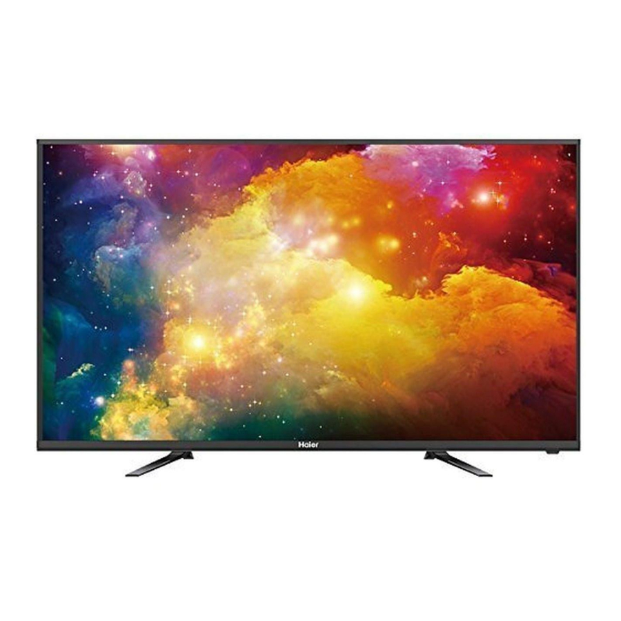
Page 9: External Pictures (Four Faces)
Service Manual Model No.:LE39B9000 2-2. External pictures (four faces) Front Side Up Side... - Page 10 Service Manual Model No.:LE39B9000 Right Side Back Side...
-
Page 11: Chapter 3. Disassemble And Assemble
Service Manual Model No.:LE39B9000 Chapter 3. Disassemble and Assemble 3-1. LE39B9000 3-1-1. Remove the Stand 3-1-3. Remove the Mainboard 1. Remove the screws indicated with red circles in above picture. 2. Remove the Mainboard Module. 1. Lay down the TV set . -
Page 12: Remove The Remote Control Board
Service Manual Model No.:LE39B9000 3-1-5. Remove the Remote Control Board And the Key Board Remove the Remote Control Board and the Key Board indicated by red circle in below picture. -
Page 13: Chapter 4. Location Of Controls And Components
Service Manual Model No.:LE39B9000 Chapter 4. Location of Controls and Components 4-1. Board Location B Panel A With Power supply Main Board Parts Type Description A Board TP.VST59S.PB813 With Power Supply Main board B Board AUO T390XVN01.0 LED Panel... -
Page 14: Mainboard
Service Manual Model No.:LE39B9000 4-2. Mainboard 4-2-1. Function Description Process signal which incept from exterior equipment then translate into signal that panel can display. 4-2-2. Connector definition... -
Page 15: 4-3.Led Panel
Service Manual Model No.:LE39B9000 4-3. LED Panel LE39B9000 Backlight Unit LVDS Connector... -
Page 16: Led Panel Lvds Interface Connections
Service Manual Model No.:LE39B9000 4-4. LED Panel LVDS Interface Connections... -
Page 17: Chapter 5. Installation Instructions
Service Manual Model No.:LE39B9000 Chapter 5. Installation Instructions 5-1. Accessories... -
Page 18: Base Stand Assembly Instruction
Service Manual Model No.:LE39B9000 5-2. Base Stand Assembly Instruction... -
Page 19: Front Panel Controls
Service Manual Model No.:LE39B9000... -
Page 20: Back Panel Controls
Service Manual Model No.:LE39B9000... -
Page 21: Setting Up Your Remote Control
Service Manual Model No.:LE43B7000 6-3. Setting Up Your Remote Controls... -
Page 22: Chapter 7. Electrical Parts
Service Manual Model No.:LE43B7000 Chapter 7. Electrical Parts 7-1. Circuit Diagram +1.2V-VDDC 500mA DC-DC 1.26V +3.3V-STB 100mA LDO 3.3V-STB VST59S Si TUNER HDMI1 IN HDMID +2.5/1.8V DDR LDO 2.5/1.8V 250mA HDMI2 IN HDMIA 5V-SB +5V P5V +12V PW ON POWER PANEL GPIO 64 PC AUDIO IN... - Page 23 RB125 RB126 CB118 RB127 RB128 DB102 TB101 DB103 Vbridge RB141 CB117 RB129 RB130 RB142 SGND BB101 DB106 CYB1 Vbridge EB102 T3.15AL 250V~ QB101 DB101 RB106 CB116 CXB1 RB101 LCB1 SGND CNB1 CYB2 LCB2 RB107 SGND RB109 SGND RB102 NTCB1 UB101 QB102 RB108 GATE...
- Page 24 RD15 CD13 TEST UD11 5V-STB 5V-STB LD12 5V-M UL41 DDR-2.5V/1.8V TEST 2V5/1V8 CD11 CD12 RD11 CD14 CD15 5V-STB 3V3-STB 3V3_STB RD12 TEST RD13 CL42 CL44 CL43 1uF-0402-X5R-± 20%-6.3V RD16 22ohm-0402-± 5%-1/16W CTD0504-4R7-M 0.1uF-0402-X5R-± 20%-16V MP1470GJ-Z 30Kohm-0402-± 1%-1/16W 10uF-0805-X5R-± 20%-16V 5K6ohm-0402-± 1%-1/16W 0.1uF-0402-X5R-±...
- Page 25 AV2-IN/ SCART-VI NC/33ohm-0402-± 5%-1/16W NC/75ohm-0402-± 5%-1/16W AV1-IN NC/0.047uF-0402-X7R-± 10%-16V AV2-IN/ AV2-RIN/ AV2-LIN/ AV1-IN/ 75ohm-0402-±5%-1/16W 33ohm-0402-±5%-1/16W NC/2×2PIN-2.0-L-H-F- 0.047uF-0402-X7R-± 10%-16V RS10 AV2-LIN/ SC-LI 10uF-0603-X5R-± 20%-6.3V RS11 AV1-8.4-17C AV1-L/ AV1-LIN NC/8K2ohm-0402-±5%-1/16W NC/12Kohm-0402-±5%-1/16W CS28 SCART-VOUT/ SCART-VOUT NC/1uF-0402-X5R-± 20%-6.3V 56Kohm-0402-± 5%-1/16W AV2-RIN/ NC/12Kohm-0402-±5%-1/16W 1uF-0402-X5R-± 20%-6.3V AV1-R/ AV2-IN/ AV2-LIN/...
- Page 26 3V3-STB 3V3-STB UF11 5V-IR RK12 5V-STB RF14 LED-R RK13 LED-R/ XTALO SPI-CSN CF13 LED-G/B RK10 3V3-STB SPI-SDO HOLD# K0/S K0/AD KEYA K1/C+ 3V3-STB SPI-SCK 4K7ohm-0402-± 5%-1/16W XTALI K2/C- 0.1uF-0402-X5R-± 20%-16V K3/V+ SPI-SDI GD25Q32BSIG K4/V- K5/M 24MHz-±20PPM-20PF-HC-49S K6/P K6/AD 1Mohm-0402-±5%-1/16W K7/N KEYB 33pF-0402-NPO-±5%-50V 33pF-0402-NPO-±5%-50V...
- Page 27 HDMI1-5V HDMI1-5V CN15 HDMI1-RX2-P RX2+ HDMI1-RX2-N RX2- HOTPLUG1 HDMI1-RX1-P 0ohm-0402-± 5%-1/16W SHELL(GND) RX1+ 0ohm-0402-± 5%-1/16W HDMI1-RX1-N NC/47Kohm-0402-± 5%-1/16W RX1- HDMI1-RX0-P RX0+ HOTPLUGA SHELL(GND) HDMI1-RX0-N RX0- 1Kohm-0402-± 5%-1/16W HDMI1-RXC-P RXC+ LMBT3904LT1G 10Kohm-0402-± 5%-1/16W HDMI1-RXC-N SHELL(GND) RXC- 10Kohm-0402-± 5%-1/16W CEC1 RH15 HDMI1-SCL/ HDMI1-SCL RH16 HDMI1-SDA/...
- Page 28 AMP-AMP-STB AMP-STB/ AVCC RA34 AMP-PVCCL 10ohm-0402-± 5%-1/16W 0.22uF-0402-X5R-± 10%-16V SLN54T-220K 510ohm-0402-± 5%-1/16W 0.22uF-0402-X5R-± 10%-16V SLN54T-220K 10Kohm-0402-± 5%-1/16W 0.22uF-0402-X5R-± 10%-16V 0.22uF-0402-X5R-± 10%-16V SLN54T-220K 0.22uF-0402-X5R-± 10%-16V AMP-PVCCL 0.22uF-0402-X5R-± 10%-16V SLN54T-220K 0.22uF-0402-X5R-± 10%-16V 1000pF-0402-X7R-± 10%-50V 1uF-0402-X5R-± 20%-16V 0.22uF-0402-X5R-± 10%-16V NC/0.1uF-0402-Y5V-+80%-20%-25V 1uF-0402-X5R-± 20%-16V 1Kohm-0402-± 5%-1/16W 1uF-0603-X5R-±...
- Page 29 3V3-STB CT20 RT18 VIFM TUNER-SDA/ M-SDA IF-AGC TAGC TUNER-SCL/ M-SCL CT23 RT10 VIFP 100ohm-0402-± 5%-1/16W 10Kohm-0402-± 5%-1/16W 100ohm-0402-± 5%-1/16W 10Kohm-0402-± 5%-1/16W 0.1uF-0402-X5R-± 20%-16V 220ohm-0402-± 5%-1/16W 0.1uF-0402-X5R-±20%-16V 220ohm-0402-± 5%-1/16W 0.1uF-0402-X5R-±20%-16V 3V3-STB 0.1uF-0402-X5R-± 20%-16V GND GND 0.1uF-0402-X5R-± 20%-16V 0.022uF-0402-X7R-± 10%-16V SDCL1005C68NJTDF(68nH-0402± 5%-C) 3V3-STB 1Kohm-0402-±...
-
Page 30: Software Update
Service Manual Model No.:LE43B7000 Chapter 8. Software Update 8-1.Software Update 1-1. bin_v59s_49.bin software update 1-2. Copy the software files to a USB disk on the root directory; 1-3. Insert the USB disk when the AC power is off; 1-4. Turn on the AC power in turn to begin; 1-5. -
Page 31: Chapter 9. Trouble Shooting
Service Manual Model No.:LE43B7000 Chapter 9. Trouble shooting 9-1.Trouble shooting... -
Page 32: Wiring Connection Diagram
Service Manual Model No.:LE49B7000... - Page 33 Service Manual Model No.:LE49B7000...
-
Page 34: 9-1.Powertroubleshooting
Service Manual Model No.:LE49B7000... -
Page 35: 9-2.Display Troubleshooting(Blank Screen Or Shouw Nothing)
Service Manual Model No.:LE49B7000... -
Page 36: 9-3.Display Troubleshooting(White Screen)
Service Manual Model No.:LE49B7000... -
Page 37: 9-4.Display Troubleshooting(Picture Badness)
Service Manual Model No.:LE43B7000 Sincere Forever Haier Group Haier Industrial Park, No.1, Haier Road 266101, Qingdao, China http://www.haier.com Printed in China...