Advertisement
Available languages
Available languages
Quick Links
Quick Start
Thank you for purchasing the MSI
H370 GAMING PRO CARBON/
®
B360 GAMING PRO CARBON
motherboard. This Quick Start section
provides demonstration diagrams about how to install your computer.
Some of the installations also provide video demonstrations. Please
link to the URL to watch it with the web browser on your phone or
tablet. You may have even link to the URL by scanning the QR code.
Kurzanleitung
Danke, dass Sie das MSI
H370 GAMING PRO CARBON/ B360
®
GAMING PRO CARBON
Motherboard gewählt haben. Dieser Abschnitt
der Kurzanleitung bietet eine Demo zur Installation Ihres Computers.
Manche Installationen bieten auch die Videodemonstrationen.
Klicken Sie auf die URL, um diese Videoanleitung mit Ihrem Browser
auf Ihrem Handy oder Table anzusehen. Oder scannen Sie auch den
QR Code mit Ihrem Handy, um die URL zu öffnen.
Présentation rapide
Merci d' avoir choisi la carte mère MSI
H370 GAMING PRO
®
CARBON/ B360 GAMING PRO
CARBON. Ce manuel fournit une rapide
présentation avec des illustrations explicatives qui vous aideront à
assembler votre ordinateur. Des tutoriels vidéo sont disponibles pour
certaines étapes. Cliquez sur le lien fourni pour regarder la vidéo sur
votre téléphone ou votre tablette. Vous pouvez également accéder au
lien en scannant le QR code qui lui est associé.
Быстрый старт
Благодарим вас за покупку материнской платы MSI
H370
®
CARBON. В этом
GAMING PRO CARBON/ B360 GAMING PRO
разделе представлена информация, которая поможет
вам при сборке комьютера. Для некоторых этапов
сборки имеются видеоинструкции. Для просмотра видео,
необходимо открыть соответствующую ссылку в веб-
браузере на вашем телефоне или планшете. Вы также
можете выполнить переход по ссылке, путем сканирования
QR-кода.
I
Quick Start
Advertisement

Related Manuals for MSI H370


Summary of Contents for MSI H370
- Page 1 Klicken Sie auf die URL, um diese Videoanleitung mit Ihrem Browser auf Ihrem Handy oder Table anzusehen. Oder scannen Sie auch den QR Code mit Ihrem Handy, um die URL zu öffnen. Présentation rapide Merci d’ avoir choisi la carte mère MSI H370 GAMING PRO ® CARBON/ B360 GAMING PRO CARBON.
- Page 2 Installing a Processor/ Installation des Prozessors/ Installer un processeur/ Установка процессора http://youtu.be/bf5La099urI Quick Start...
- Page 3 Installing DDR4 memory/ Installation des DDR4-Speichers/ Installer une mémoire DDR4/ Установка памяти DDR4 http://youtu.be/T03aDrJPyQs DIMMB2 DIMMB2 DIMMB1 DIMMA2 DIMMA2 DIMMA2 DIMMA1 Quick Start...
- Page 4 Connecting the Front Panel Header/ Anschließen der Frontpanel-Stiftleiste/ Connecter un connecteur du panneau avant/ Подключение разъемов передней панели http://youtu.be/DPELIdVNZUI HDD LED + Power LED + HDD LED - Power LED - Reset Switch Power Switch Reset Switch Power Switch JFP1 Reserved No Pin JFP1...
- Page 5 Installing the Motherboard/ Installation des Motherboards/ Installer la carte mère/ Установка материнской платы BAT1 Quick Start...
- Page 6 Installing SATA Drives/ Installation der SATA-Laufwerke/ Installer le disque dur SATA/ Установка дисков SATA http://youtu.be/RZsMpqxythc Quick Start...
- Page 7 Installing a Graphics Card/ Einbau der Grafikkarte/ Installer une carte graphique/ Установка дискретной видеокарты http://youtu.be/mG0GZpr9w_A Quick Start...
- Page 8 Connecting Peripheral Devices/ Peripheriegeräte/ Connecter un périphérique anschliessen/ Подключение периферийных устройств VIII Quick Start...
- Page 9 Connecting the Power Connectors/ Stromanschlüsse anschliessen/ Connecter les câbles du module d’ alimentation/ Подключение разъемов питания http://youtu.be/gkDYyR_83I4 ATX_PWR1 CPU_PWR1 Quick Start...
- Page 10 Power On/ Einschalten/ Mettre sous-tension/ Включение питания Quick Start...
- Page 11 Contents Safety Information ....................2 Specifications ......................3 JCORSAIR1 Connector Specification ..............7 Rear I/O Panel ....................... 8 LAN Port LED Status Table..................8 Audio Ports Configuration ..................8 Realtek HD Audio Manager ..................9 Overview of Components ..................11 CPU Socket ......................
- Page 12 Safety Information y The components included in this package are prone to damage from electrostatic discharge (ESD). Please adhere to the following instructions to ensure successful computer assembly. y Ensure that all components are securely connected. Loose connections may cause the computer to not recognize a component or fail to start.
- Page 13 * SATA2 port will be unavailable when an M.2 SATA SSD module has been installed in the M2_1 slot. ** Before using Intel Optane™ memory modules, please ensure that you have ® updated the drivers and BIOS to the latest version from MSI website. Continued on next page Specifications...
- Page 14 1 Type-C port available through the internal USB connector) ƒ 4x USB 3.1 Gen1 (SuperSpeed USB) ports available through the internal USB connectors (H370 GAMING PRO CARBON) ƒ 2x USB 3.1 Gen1 (SuperSpeed USB) ports available through the internal USB connector (B360 GAMING PRO CARBON) ƒ...
- Page 15 1x USB 3.1 Gen 2 Type-C connector y 2x USB 3.1 Gen1 connectors (supports additional 4 USB 3.1 Gen1 ports) (H370 GAMING PRO CARBON) y 1x USB 3.1 Gen1 connector (supports additional 2 USB 3.1 Gen1 ports) (B360 GAMING PRO CARBON) y 2x USB 2.0 connectors (supports additional 4 USB 2.0...
- Page 16 GAMING APP y MYSTIC LIGHT y GAMING LAN MANAGER y Nahimic Audio y Open Broadcaster Software (OBS) y CPU-Z MSI GAMING y Intel Extreme Tuning Utility ® y Google Chrome™ ,Google Toolbar, Google Drive y Norton™ Internet Security Solution y Audio ƒ...
- Page 17 ƒ Mystic Light Extension (RGB) ƒ Mystic Light Extension (CORSAIR) ƒ Mystic light SYNC ƒ EZ DEBUG LED y Protection ƒ M.2 Shield (H370 only) ƒ PCI-E Steel Armor y Performance ƒ Multi GPU – CrossFire Technology ƒ DDR4 Boost Special Features ƒ...
- Page 18 Rear I/O Panel Audio Ports USB 3.1 Gen1 PS/2 USB 3.1 Gen2 DisplayPort USB 2.0 Optical S/PDIF-Out USB 3.1 Gen2 USB 3.1 Gen1 Type-C LAN Port LED Status Table Link/ Activity LED Speed LED Status Description Status Description No link 10 Mbps connection Yellow Linked...
- Page 19 Realtek HD Audio Manager After installing the Realtek HD Audio driver, the Realtek HD Audio Manager icon will appear in the system tray. Double click on the icon to launch. Device Selection Advanced Settings Jack Status Application Enhancement Main Volume Connector Strings Profiles...
- Page 20 Audio jacks to headphone and microphone diagram Audio jacks to stereo speakers diagram AUDIO INPUT Audio jacks to 7.1-channel speakers diagram AUDIO INPUT Rear Front Side Center/ Subwoofer Rear I/O Panel...
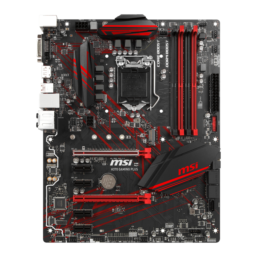
- Page 21 Overview of Components DIMMA1 SYS_FAN1 DIMMA2 CPU_FAN1 CPU_PWR1 DIMMB1 DIMMB2 CPU Socket PUMP_FAN1 JCORSAIR1 SYS_FAN2 ATX_PWR1 SYS_FAN3 JUSB5 M2_1 JBAT1 PCI_E1 JUSB4 BAT1 SATA▼1▲2 PCI_E2 SATA▼3▲4 PCI_E3 SATA▼5▲6 PCI_E4 M2_2 PCI_E5 JCI1 JFP1 JFP2 JAUD1 JUSB1 JRGB1 JUSB2 JRAINBOW1 JUSB3 SYS_FAN5 JTPM1 SYS_FAN4...
- Page 22 Always unplug the power cord from the power outlet before installing or removing the CPU. Please retain the CPU protective cap after installing the processor. MSI will deal with Return Merchandise Authorization (RMA) requests if only the motherboard comes with the protective cap on the CPU socket.
- Page 23 DIMM Slots DIMMA1 DIMMB1 Channel A Channel B DIMMA2 DIMMB2 Memory module installation recommendation DIMMB2 DIMMB2 DIMMB1 DIMMA2 DIMMA2 DIMMA2 DIMMA1 Important Always insert memory modules in the DIMMA2 slot first. Due to chipset resource usage, the available capacity of memory will be a little less than the amount of installed.
- Page 24 If you install a large and heavy graphics card, you need to use a tool such as MSI Gaming Series Graphics Card Bolster to support its weight and to prevent deformation of the slot. PCI_E3 slot will be unavailable when an M.2 PCIe SSD module has been installed in the M2_2 slot.
- Page 25 Supplied M.2 screw 30° Using M.2 shield (H370 only) We provide the M.2 shield on the M2_1 slot to help dissipate heat away from the M.2 SSD. Before installing the M.2 SSD for the first time, you need to remove the screw, lift the cover and remove the protective film and the round rubber from the thermal pad.
- Page 26 SATA1~6: SATA 6Gb/s Connectors These connectors are SATA 6Gb/s interface ports. Each connector can connect to one SATA device. SATA2 SATA1 SATA4 SATA3 SATA6 SATA5 Important SATA2 port will be unavailable when an M.2 SATA SSD module has been installed in the M2_1 slot.
- Page 27 CPU_PWR1, ATX_PWR1: Power Connectors These connectors allow you to connect an ATX power supply. CPU_PWR1 Ground +12V Ground +12V Ground +12V Ground +12V +3.3V +3.3V +3.3V -12V Ground Ground PS-ON# Ground Ground Ground ATX_PWR1 Ground Ground PWR OK 5VSB +12V +12V +3.3V Ground...
- Page 28 JFP1, JFP2: Front Panel Connectors These connectors connect to the switches and LEDs on the front panel. JFP1 HDD LED + Power LED + HDD LED - Power LED - Reset Switch Power Switch Reset Switch Power Switch Reserved No Pin Speaker - Buzzer + JFP2...
- Page 29 In order to recharge your iPad,iPhone and iPod through USB ports, please install SUPER CHARGER utility. ® JUSB3~4: USB 3.1 Gen1 Connectors (optional) These connectors allow you to connect USB 3.1 Gen1 ports on the front panel. JUSB4 JUSB3 (For H370 only) Power USB2.0+ USB3_RX_DN USB2.0- USB3_RX_DP Ground...
- Page 30 CPU_FAN1,SYS_FAN1~5, PUMP_FAN1: Fan Connectors Fan connectors can be classified as PWM (Pulse Width Modulation) Mode or DC Mode. PWM Mode fan connectors provide constant 12V output and adjust fan speed with speed control signal. DC Mode fan connectors control fan speed by changing voltage. When you plug a 3-pin (Non-PWM) fan to a fan connector in PWM mode, the fan speed will always maintain at 100%, which might create a lot of noise.
- Page 31 JAUD1: Front Audio Connector This connector allows you to connect audio jacks on the front panel. MIC L Ground MIC R Head Phone R MIC Detection SENSE_SEND No Pin Head Phone L Head Phone Detection JCI1: Chassis Intrusion Connector This connector allows you to connect the chassis intrusion switch cable. Normal Trigger the chassis intrusion event...
- Page 32 JTPM1: TPM Module Connector This connector is for TPM (Trusted Platform Module). Please refer to the TPM security platform manual for more details and usages. LPC Clock 3V Standby power LPC Reset 3.3V Power LPC address & data pin0 Serial IRQ LPC address &...
- Page 33 Please keeping the LED strip shorter than 2 meters to prevent dimming. Always turn off the power supply and unplug the power cord from the power outlet before installing or removing the RGB LED strip. Please use MSI’ s software to control the extended LED strip. Overview of Components...
- Page 34 The JCORSAIR1 connector allows you to connect the CORSAIR Individually Addressable Lighting PRO RGB LED strips 5V or CORSAIR RGB fans with the CORSAIR fan hub. Once all items are connected properly, you can control the CORSAIR RGB LED strips and fans with MSI's software. JCORSAIR1 Data...
- Page 35 Onboard LEDs EZ Debug LED These LEDs indicate the status of key components during booting process. When an error is occurred, the corresponding LED stays lit until the problem is solved. CPU - indicates CPU is not detected or fail. DRAM - indicates DRAM is not detected or fail.
- Page 36 Press Delete key, when the Press DEL key to enter Setup Menu, F11 to enter Boot Menu message appears on the screen during the boot process. y Use MSI FAST BOOT application. Click on GO2BIOS button and choose OK. The system will reboot and enter BIOS setup directly.
- Page 37 Updating BIOS Updating BIOS with M-FLASH Before updating: Please download the latest BIOS file that matches your motherboard model from MSI website. And then save the BIOS file into the USB flash drive. Updating BIOS: 1. Insert the USB flash drive that contains the update file into the computer.
- Page 38 EZ Mode At EZ mode, it provides the basic system information and allows you to configure the basic setting. To configure the advanced BIOS settings, please enter the Advanced Mode by pressing the Setup Mode switch or F7 function key. XMP switch Setup Mode switch Screenshot...
- Page 39 y Information display - click on the CPU, Memory, Storage, Fan Info and Help buttons on left side to display related information. y Function buttons - enable or disable the LAN Option ROM, M.2/ Optane Genie, HD audio controller, AHCI, RAID, CPU Fan Fail Warning Control and BIOS Log Review by clicking on their respective button.
- Page 40 Advanced Mode Press Setup Mode switch or F7 function key can switch between EZ Mode and Advanced Mode in BIOS setup. XMP switch Setup Mode switch Screenshot Search Language System information Boot device priority bar BIOS menu BIOS menu selection selection Menu display y XMP switch/ Setup Mode switch/ Screenshot/ Language/ System information/ Boot...
- Page 41 OC Menu This menu is for advanced users who want to overclock the motherboard. Important Overclocking your PC manually is only recommended for advanced users. Overclocking is not guaranteed, and if done improperly, it could void your warranty or severely damage your hardware. f OC Explore Mode [Normal] Enables or disables to show the normal or expert version of OC settings.
- Page 42 f Core X X of X xxxx MHz [Auto]* Allows you to set the CPU ratios for different number of active cores. These items only appear when CPU Ratio Apply Mode set to Per Core. f CPU Ratio Offset When Running AVX [Auto] Sets a offset value to lower the CPU core ratio.
- Page 43 f DRAM Frequency [Auto] Sets the DRAM frequency. Please note the overclocking behavior is not guaranteed. f Adjusted DRAM Frequency Shows the adjusted DRAM frequency. Read-only. f Memory Try It ! [Disabled] It improve memory compatibility or performance by choosing optimized memory preset.
- Page 44 f CPU Specifications Press Enter to enter the sub-menu. This sub-menu displays the information of installed CPU. You can also access this information menu at any time by pressing [F4]. Read only. fCPU Technology Support Press Enter to enter the sub-menu. The sub-menu shows the key features of installed CPU.
- Page 45 fHardware Prefetcher [Enabled] Enables or disables the hardware prefetcher (MLC Streamer prefetcher). [Enabled] Allows the hardware prefetcher to automatically pre-fetch data and instructions into L2 cache from memory for tuning the CPU performance. [Disabled] Disables the hardware prefetcher. fAdjacent Cache Line Prefetch [Enabled] Enables or disables the CPU hardware prefetcher (MLC Spatial prefetcher).
- Page 46 fLong Duration Power Limit (W) [Auto] Sets the long duration TDP power limit for CPU in Turbo Boost mode. fLong Duration Maintained (s) [Auto] Sets the maintaining time for Long duration power Limit(W). fShort Duration Power Limit (W) [Auto] Sets the short duration TDP power limit for CPU in Turbo Boost mode. fCPU Current Limit (A) [Auto] Sets maximum current limit of CPU package in Turbo Boost mode.
- Page 47 Software Description Please download and update the latest utilities and drivers at www.msi.com Installing Windows ® 1. Power on the computer. 2. Insert the Windows 10 disc into your optical drive. ® 3. Press the Restart button on the computer case.
- Page 49 Inhalt Sicherheitshinweis ....................2 Spezifikationen ...................... 3 JCORSAIR1 Anschluss-Spezifikationen ..............8 Rückseite E/A ......................9 LAN Port LED Zustandstabelle ................9 Konfiguration der Audioanschlüsse ............... 9 Realtek HD Audio Manager .................. 10 Übersicht der Komponenten ................12 CPU Sockel ......................13 DIMM-Steckplätze ....................
- Page 50 Sicherheitshinweis y Die im Paket enthaltene Komponenten sind der Beschädigung durch elektrostatischen Entladung (ESD). Beachten Sie bitte die folgenden Hinweise, um die erfolgreichen Computermontage sicherzustellen. y Stellen Sie sicher, dass alle Komponenten fest angeschlossen sind. Lockere Steckverbindungen können Probleme verursachen, zum Beispiel: Der Computer erkennt eine Komponente nicht oder startet nicht.
- Page 51 Modul im M2_1-Steckplatz installieren. ** Bevor Sie Intel Optane Speichermodule verwenden, stellen Sie bitte über ® ™ Downloads von der MSI Website sicher, dass die Treiber und das BIOS auf dem neuesten Stand sind. Fortsetzung auf der nächsten Seite Spezifikationen...
- Page 52 Anschlussleiste, 1 Typ-C Anschluss steht durch die internen USB Anschluss zur Verfügung) ƒ 4x USB 3.1 Gen1 (SuperSpeed USB) Anschlüsse stehen durch die internen USB Anschluss zur Verfügung (H370 GAMING PRO CARBON) ƒ 2x USB 3.1 Gen1 (SuperSpeed USB) Anschlüsse stehen durch die internen USB Anschluss zur Verfügung (B360...
- Page 53 1x USB 3.1 Gen 2 Typ-C Anschluss y 2x USB 3.1 Gen1 Anschlüsse (unterstützt zusätzliche 4 USB 3.1 Gen1-Ports) (H370 GAMING PRO CARBON) y 1x USB 3.1 Gen1 Anschluss (unterstützt zusätzliche 2 USB 3.1 Gen1-Ports) (B360 GAMING PRO CARBON) y 2x USB 2.0 Anschlüsse (unterstützt zusätzliche 4...
- Page 54 DPC LATENCY TUNER y GAMING APP y MYSTIC LIGHT y GAMING LAN MANAGER y Nahimic Audio y Open Broadcaster Software (OBS) y CPU-Z MSI GAMING y Intel Extreme Tuning Utility ® y Google Chrome , Google Toolbar, Google Drive ™...
- Page 55 ƒ Mystic Light ƒ Mystic Light Extension (RAINBOW) ƒ Mystic Light Extension (RGB) ƒ Mystic Light Extension (CORSAIR) ƒ Mystic Light SYNC ƒ EZ DEBUG LED y Schutz ƒ M.2-Abdeckung (nur H370) ƒ PCI-E Steel Armor Fortsetzung auf der nächsten Seite Spezifikationen...
- Page 56 Fortsetzung der vorherigen Seite y Leistung ƒ Multi GPU – CrossFire Technologie ƒ DDR4 Boost ƒ USB Anschluss mit Typ A+C ƒ Intel Turbo USB 3.1 Gen2 y Stabilität ƒ 7000+ Quality Test y VR Besondere Funktionen ƒ VR Ready y Gamer-Erfahrungen ƒ...
- Page 57 Rückseite E/A Audioanschlüsse USB 3.1 Gen1 PS/2 USB 3.1 Gen2 DisplayPort USB 2.0 Optischer S/PDIF- Ausgang USB 3.1 Gen2 USB 3.1 Gen1 Typ-C LAN Port LED Zustandstabelle Verbindung/ Aktivität LED Geschwindigkeit LED Zustand Bezeichnung Zustand Bezeichnung Keine Verbindung 10 Mbps-Verbindung Gelb Verbindung Grün...
- Page 58 Realtek HD Audio Manager Nach der Installation des Realtek HD Audio-Treibers, wird das Symbol Realtek HD Audio Manager in der Taskleiste angezeigt. Klicken Sie doppelt auf dieses Symbol, um das Programm zu starten. Geräteauswahl Erweiterte Einstellungen Verbindungs- status Optimierungen Lautstärke Anschlüsse Profil y Geräteauswahl - Ermöglicht die Auswahl der Audio-Ausgangs Quelle.
- Page 59 Audiobuchsen für den Anschluss von einem Kopfhörer und Mikrofon Audiobuchsen für Stereo-Lautsprecher AUDIO INPUT Audiobuchsen für 7.1 Kanal Anlage AUDIO INPUT Rear Front Side Center/ Subwoofer Rückseite E/A...
- Page 60 Übersicht der Komponenten DIMMA1 SYS_FAN1 DIMMA2 CPU_FAN1 CPU_PWR1 DIMMB1 DIMMB2 CPU Sockel PUMP_FAN1 JCORSAIR1 SYS_FAN2 ATX_PWR1 SYS_FAN3 JUSB5 M2_1 JBAT1 PCI_E1 JUSB4 BAT1 SATA▼1▲2 PCI_E2 SATA▼3▲4 PCI_E3 SATA▼5▲6 PCI_E4 M2_2 PCI_E5 JCI1 JFP1 JFP2 JAUD1 JUSB1 JRGB1 JUSB2 JRAINBOW1 JUSB3 SYS_FAN5 JTPM1 SYS_FAN4...
- Page 61 Sie jedoch bitte sicher, dass die betroffenen Komponenten mit den abweichenden Einstellungen während des Übertaktens zurecht kommen. Von jedem Versuch des Betriebes außerhalb der Produktspezifikationen kann nur abgeraten werden. MSI übernehmt keinerlei Garantie für die Schäden und Risiken, die aus einem unzulässigem Betrieb oder einem Betrieb außerhalb der Produktspezifikation resultieren.
- Page 62 DIMM-Steckplätze DIMMA1 DIMMB1 Kanal A Kanal B DIMMA2 DIMMB2 Speichermodul-Installationsempfehlung DIMMB2 DIMMB2 DIMMB1 DIMMA2 DIMMA2 DIMMA2 DIMMA1 Wichtig Um einen sicheren Systemstart zu gewährleisten, bestücken Sie immer DIMMA2 zuerst. Aufgrund der Chipsatzressourcennutzung wird die verfügbare Kapazität des Speichers kleiner sein als die Größe der installierten Speicherkapazität. Basierend auf der Intel CPU Spezifikation wird eine Speicherspannung unter 1,35 Volt vorgeschlagen, um die CPU zu schützen.
- Page 63 PCI_E1~5: PCIe Erweiterungssteckplätze PCI_E1: PCIe 3.0 x16 (CPU Lanes) BAT1 PCI_E2: PCIe 3.0 x1 (PCH Lanes) PCI_E3: PCIe 3.0 x4 (PCH Lanes) PCI_E4: PCIe 3.0 x1 (PCH Lanes) PCI_E5: PCIe 3.0 x1 (PCH Lanes) Mehrere Grafikkarten Einbauempfehlung Wichtig Für die Installation einer einzelnen PCIe x16 Erweiterungskarte mit optimaler Leistung, empfehlen wir den PCI_E1 Steckplatz zu verwenden.
- Page 64 M.2-Schraube fest. Mitgelieferte M.2-Schraube 30° M.2-Abdeckung verwenden (nur H370) Wir setzen eine M.2-Abdeckung auf dem M2_1- Steckplatz ein, um die Abwärme des M.2-Moduls effizient abführen zu können. Bevor Sie das M.2-Modul erstmals installieren, sollten Sie die Schraube entfernen, die M.2-Abdeckung...
- Page 65 SATA1~6: SATA 6Gb/s Anschlüsse Dieser Anschluss basiert auf der Hochgeschwindigkeitsschnittstelle SATA 6 Gb/s. Pro Anschluss kann ein SATA Gerät angeschlossen werden. SATA2 SATA1 SATA4 SATA3 SATA6 SATA5 Wichtig Der SATA2-Steckplatz wird nicht zur Verfügung, wenn Sie ein M.2 SATA SSD Modul im M2_1-Steckplatz installieren.
- Page 66 CPU_PWR1, ATX_PWR1: Stromanschlüsse Mit diesen Anschlüssen verbinden Sie die ATX Stromstecker. CPU_PWR1 Ground +12V Ground +12V Ground +12V Ground +12V +3.3V +3.3V +3.3V -12V Ground Ground PS-ON# Ground Ground Ground ATX_PWR1 Ground Ground PWR OK 5VSB +12V +12V +3.3V Ground Wichtig Stellen Sie sicher, dass alle Anschlüsse mit den richtigen Anschlüssen des Netzteils verbunden sind, um einen stabilen Betrieb der Hauptplatine sicherzustellen.
- Page 67 JFP1, JFP2: Frontpanel-Anschlüsse Diese Anschlüsse verbinden die Schalter und LEDs des Frontpanels. JFP1 HDD LED + Power LED + HDD LED - Power LED - Reset Switch Power Switch Reset Switch Power Switch Reserved No Pin Speaker - Buzzer + JFP2 Buzzer - Speaker +...
- Page 68 Bitte beachten Sie, dass Sie die mit VCC (Stromführende Leitung) und Ground (Erdung) bezeichneten Pins korrekt verbinden müssen, ansonsten kann es zu Schäden kommen. Um ein iPad, iPhone und einen iPod über USB-Anschlüsse aufzuladen, installieren Sie bitte die MSI SUPER CHARGER Software. ® JUSB3~4: USB 3.1 Gen1 Anschlüsse (optional) Mit diesen Anschlüssen können Sie die USB 3.1 Gen1 Anschlüsse auf dem Frontpanel...
- Page 69 CPU_FAN1,SYS_FAN1~5, PUMP_FAN1: Stromanschlüsse für Lüfter Diese Anschlüsse können im PWM (Pulse Width Modulation) Modus oder Spannungsmodus betrieben werden. Im PWM-Modus bieten die Lüfteranschlüsse konstante 12 V Ausgang und regeln die Lüftergeschwindigkeit per Drehzahlsteuersignal. Im DC-Modus bestimmen die Lüfteranschlüsse die Lüftergeschwindigkeit durch Ändern der Spannung. Wenn Sie ein 3-Pin (Non-PWM) Lüfter an einen PWM-Modus Lüfteranschluss anschließen, läuft der Lüfter mit höchster Drehzahl und kann unangenehm laut werden.
- Page 70 JAUD1: Audioanschluss des Frontpanels Dieser Anschluss ermöglicht den Anschluss von Audiobuchsen eines Frontpanels. MIC L Ground MIC R Head Phone R MIC Detection SENSE_SEND No Pin Head Phone L Head Phone Detection JCI1: Gehäusekontaktanschluss Dieser Anschluss wird mit einem Kontaktschalter verbunden. Normal Löse den Gehäuseeingriff aus...
- Page 71 JTPM1: TPM Anschluss Dieser Anschluss wird für das TPM Modul (Trusted Platform Module) verwendet. Weitere Informationen über den Einsatz des optionalen TPM Modules entnehmen Sie bitte dem TPM Plattform Handbuch. LPC Clock 3V Standby power LPC Reset 3.3V Power LPC address & data pin0 Serial IRQ LPC address &...
- Page 72 Beachten Sie bitte, dass die Länge des LED-Streifens maximal 2 Meter betragen darf um eine Verdunkelung der LED zu verhindern. Schalten Sie die Stromversorgung aus und ziehen Sie das Netzkabel ab, bevor Sie die RGB-LED-Streifen ein- und ausbauen. Bitte verwenden Sie die MSI-Software zur Steuerung des LED-Leuchtstreifens. Übersicht der Komponenten...
- Page 73 Mit dem JCORSAIR1 Anschluss können Sie CORSAIR einzeln adressierbare Lighting PRO RGB-LED-Strips (5 V) oder CORSAIR RGB LED Lüfter mit dem CORSAIR-Lüfter- Hub verbinden. Nach ordnungsgemäßem Anschluss können Sie die MSI-Software zur Steuerung der CORSAIR RGB LED-Streifen und Lüfter verwenden.
- Page 74 Onboard LEDs EZ Debug LED Diese LEDs zeigen den Status der Hauptkomponenten während des Boot-Vorgangs an Im Falle eines Fehlers, leuchtet die entsprechende LED bis zur Lösung des Problems vorübergehend dauerhaft. CPU - CPU wird nicht erkannt oder ist fehlerhaft. DRAM - DRAM wird nicht erkannt oder ist fehlerhaft.
- Page 75 Während des BOOT-Vorgangs drücken Sie die Taste ENTF, wenn die Meldung Press DEL key to enter Setup Menu, F11 to enter Boot Menu erscheint. y Verwenden Sie die MSI FAST BOOT Anwendung. Klicken Sie die GO2BIOS-Taste und drücken Sie OK. Das System startet neu und geht direkt ins BIOS.
- Page 76 Aktualisierung des BIOS mit dem M-FLASH-Programm Vorbereitung: Laden Sie bitte die neueste BIOS Version, die dem Motherboard-Modell entspricht, von der offiziellen MSI Website herunter und speichern Sie die BIOS-Datei auf USB-Flash- Laufwerk. BIOS-Aktualisierungsschritte: 1. Schließen das USB-Flashlaufwerk mit der BIOS-Datei an den Computer.
- Page 77 EZ Modus Im EZ-Modus können Sie die Grundinformationen des Systems einsehen und grundlegende Einstellungen konfigurieren. Um sich die erweiterten BIOS- Einstellungen anzeigen zu lassen, aktivieren Sie bitte den Erweiterten Modus durch Drücken des Setup Modus Schalter oder der Funktionstaste F7. XMP Schalter Setup Modus Schalter Screenshot...
- Page 78 y Informationsanzeige - Klicken Sie auf die Schaltfläche CPU, Memory, Storage, Fan Info und Help auf der linken Seite, um die jeweiligen Informationen anzuzeigen. y Funktionstasten - Aktivieren oder deaktivieren Sie LAN Option ROM, M.2/ Optane Genie, HD Audio Controller, AHCI, RAID, CPU Fan Fail Warning Control und BIOS Log Review durch Anklicken der zugehörigen Schaltfläche.
- Page 79 Erweiterter Modus Drücken Sie den Setup Modus Schalter oder die Funkionstaste F7, um zwischen dem EZ-Modus und Erweiterten-Modus im BIOS-Setup zu wechseln. XMP Schalter Setup Modus Schalter Screenshot Suchen Sprache System- information Bootgeräte- Prioritätsleiste BIOS-Menü BIOS-Menü -Auswahl -Auswahl Menüanzeige y XMP Schalter/ Setup Modus Schalter/ Screenshot/ Sprache/ Systeminformation/ Boot-Geräte Prioritätsleiste - Finden Sie die Informationen in den Beschreibungen der EZ Modus-Abschritt.
- Page 80 OC Menü In diesem Menü können Benutzer das BIOS anpassen und das Mainboard übertakten. Bitte führen Sie nur Änderungen durch, wenn Sie sich über das Ergebnis im Klaren sind. Sie sollten Erfahrung beim Übertakten haben, da Sie sonst das Motherboard oder Komponenten des Systems beschädigen können.
- Page 81 f Adjusted CPU Frequency Zeigt die eingestellte Frequenz der CPU an. Es handelt sich um eine Anzeige – Änderungen sind nicht möglich. f Core X X of X xxxx MHz [Auto]* Hier können Sie die CPU Taktraten der verschiedenen aktiven Kerne anpassen. Diese Optionen kann nur geändert werden, wenn CPU Ratio Apply Mode auf Per Core eingestellt.
- Page 82 f Extreme Memory Profile (X.M.P.) [Disabled] Extreme Memory Profile (XMP) basieren auf Zertifizierungen für Speichermodule aus dem PC-Bereich. Aktivieren Sie die Funktion XMP oder wählen Sie ein Profil des Speichermoduls zum Übertakten aus. Diese Option steht zur Verfügung, wenn die installierten Speichermodule die XMP Technik unterstützen.
- Page 83 f CPU Voltages control [Auto] Erlaubt das Einstellen der CPU-Spannungen. Wenn die Einstellung auf Auto gesetzt ist, wird das BIOS die Spannungen automatisch einstellen oder Sie können es manuell einstellen. f DRAM Voltages control [Auto] Erlaubt das Einstellen der DRAM-Spannungen. Wenn die Einstellung auf Auto gesetzt ist, wird das BIOS die Spannungen automatisch einstellen oder Sie können es manuell einstellen.
- Page 84 fLimit CPUID Maximum [Disabled] Aktiviert oder deaktiviert den erweiterten CPUID-Wert. [Enabled] Das BIOS begrenzt den maximalen CPUID Eingabewert, um Bootprobleme mit älteren Betriebssystem zu umgehen, die den Prozessor mit erweiterten CPUID-Wert nicht unterstützen. [Disabled] Verwenden Sie den maximalen CPUID Eingabewert. fIntel Virtualization Tech [Enabled] Aktiviert oder deaktiviert die Intel Virtualization Technologie.
- Page 85 fC1E Support [Disabled] Aktiviert oder deaktiviert die C1E-Funktion für Stromersparnis im Leerlauf. Diese Option wird angezeigt, wenn Intel C-State aktiviert ist. [Enabled] Ermöglicht die C1E Funktion, um die CPU-Frequenz und Spannung zur Stromersparnis im Leerlauf zu reduzieren. [Disabled] Deaktiviert diese Funktion. fPackage C State limit [Auto] Hier können Sie einen CPU C-State-Modus für Stromsparen auswählen, wenn das System im Leerlauf ist.
- Page 86 Softwarebeschreibung Laden Sie die neuesten Treiber und Dienstprogramme von www.msi.com herunter und aktualisieren Sie sie. Installation von Windows ® 1. Schalten Sie den Computer ein. 2. Legen Sie die Windows 10 Disk in das optisches Laufwerk. ® 3. Drücken Sie die Taste Restart auf dem Computergehäuse.
- Page 87 Table des matière Informations de sécurité ..................2 Spécifications ......................3 Spécifications du connecteur JCORSAIR1 ............. 7 Panneau arrière Entrée/ Sortie ................8 Tableau explicatif de l’ état de la LED du port LAN ..........8 Configuration des ports audio ................8 Realtek HD Audio Manager ..................
- Page 88 Informations de sécurité y Les composants dans l’ emballage peuvent être endommagés par des décharges électrostatiques (ESD). Pour vous assurer de correctement monter votre ordinateur, veuillez vous référer aux instructions ci-dessous. y Assurez-vous de bien connecter tous les composants. En cas de mauvaise connexion, il se peut que l’...
- Page 89 Support Intel Extreme Memory Profile (XMP) ® * Veuillez vous référer au site www.msi.com pour plus d’ informations sur la mémoire compatible. y 2 x slots PCIe 3.0 x16 (support mode x16/ x4)* y 3 x slots PCIe 3.0 x1 Slots d’...
- Page 90 Type-C disponible par l’ intermédiaire du connecteur USB interne) ƒ 4 x ports USB 3.1 Gen1 (SuperSpeed USB) disponibles par l’ intermédiaire des connecteurs USB internes (H370 GAMING PRO CARBON) ƒ 2 x ports USB 3.1 Gen1 (SuperSpeed USB) disponible par l’...
- Page 91 1 x connecteur USB 3.1 Gen 2 Type-C y 2 x connecteurs USB 3.1 Gen1 (support de 4 autres ports USB 3.1 Gen1) (H370 GAMING PRO CARBON) y 1 x connecteur USB 3.1 Gen1 (support de 2 autres ports USB 3.1 Gen1) (B360 GAMING PRO CARBON)
- Page 92 GAMING APP y MYSTIC LIGHT y GAMING LAN MANAGER y Nahimic Audio y Open Broadcaster Software (OBS) y CPU-Z MSI GAMING y Intel Extreme Tuning Utility ® y Google Chrome™, Google Toolbar et Google Drive y Norton™ Internet Security Solution y Audio ƒ...
- Page 93 ƒ Mystic Light Extension (RGB) ƒ Mystic Light Extension (CORSAIR) ƒ Mystic light SYNC ƒ EZ DEBUG LED y Protection ƒ M.2 Shield (H370 uniquement) ƒ Steel Armor PCI-E y Performance ƒ Technologie Multi GPU – CrossFire ƒ DDR4 Boost Fonctions spéciales...
- Page 94 Panneau arrière Entrée/ Sortie Ports Audio USB 3.1 Gen1 PS/2 USB 3.1 Gen2 DisplayPort USB 2.0 Sortie S/PDIF optique USB 3.1 Gen2 USB 3.1 Gen1 Type-C Tableau explicatif de l’ état de la LED du port LAN LED indiquant la connexion LED indiquant la vitesse et l’...
- Page 95 Realtek HD Audio Manager Après l’ installation du pilote Realtek HD Audio, l’ icône Realtek HD Audio Manager apparaît dans la barre des tâches du système. Double-cliquez sur l’ icône pour lancer le programme. Sélection du périphérique Paramètres avancés Etat des prises Jack Amélioration d’...
- Page 96 Ilustration de l’ utilisation des ports audio dédiés au casque et au microphone Ilustration de l’ utilisation du port audio dédié aux haut-parleurs AUDIO INPUT Ilustration de l’ utilisation des ports audio dédiés aux haut-parleurs 7.1 AUDIO INPUT Rear Front Side Center/ Subwoofer...
- Page 97 Vue d’ ensemble des composants DIMMA1 SYS_FAN1 DIMMA2 CPU_FAN1 CPU_PWR1 DIMMB1 Socket processeur DIMMB2 PUMP_FAN1 JCORSAIR1 SYS_FAN2 ATX_PWR1 SYS_FAN3 JUSB5 M2_1 JBAT1 PCI_E1 JUSB4 BAT1 SATA▼1▲2 PCI_E2 SATA▼3▲4 PCI_E3 SATA▼5▲6 PCI_E4 M2_2 PCI_E5 JCI1 JFP1 JFP2 JAUD1 JUSB1 JRGB1 JUSB2 JRAINBOW1 JUSB3 SYS_FAN5...
- Page 98 électrique. Veuillez garder le capot de protection du processeur après l’ installation du processeur. Selon les exigences de RMA (Return Merchandise Authorization), MSI n’ acceptera pas les cartes mère dont le capot de protection aura été retiré.
- Page 99 Slots DIMM DIMMA1 DIMMB1 Canal A Canal B DIMMA2 DIMMB2 Installation recommandée de module mémoire DIMMB2 DIMMB2 DIMMB1 DIMMA2 DIMMA2 DIMMA2 DIMMA1 Important Veillez à toujours insérer un module de mémoire dans l’ emplacement DIMMA2 en premier. Du fait des ressources utilisées par le chipset, la capacité de mémoire disponible est un peu moins élevée que celle installée.
- Page 100 Si vous installez une carte graphique lourde, il vous faut utiliser un outil comme la barre de support MSI Gaming Series pour supporter son poids et pour éviter la déformation du slot. Le slot PCI_E3 est indisponible lorsqu’ un SSD M.2 PCIe est installé dans le slot M2_2.
- Page 101 Vis M.2 fournie 30° Utilisation de la protection M.2 Shield (H370 uniquement) Nous fournissons une protection pour le slot M2_1, appelée M.2 Shield. Cette protection permet de mieux dissiper la chaleur du SSD M.2. Avant d’ installer le SSD M.2 pour la première fois, vous devez enlever la vis, soulever le...
- Page 102 SATA1~6 : Connecteurs SATA 6 Gb/s Ces connecteurs utilisent une interface SATA 6 Gb/s. Chaque connecteur peut être relié à un appareil SATA. SATA2 SATA1 SATA4 SATA3 SATA6 SATA5 Important Le port SATA2 est indisponible lorsqu’ un SSD M.2 SATA est installé dans le slot M2_1.
- Page 103 CPU_PWR1, ATX_PWR1 : Connecteurs d’ alimentation Ces connecteurs vous permettent de relier une alimentation ATX. CPU_PWR1 Ground +12V Ground +12V Ground +12V Ground +12V +3.3V +3.3V +3.3V -12V Ground Ground PS-ON# Ground Ground Ground ATX_PWR1 Ground Ground PWR OK 5VSB +12V +12V +3.3V...
- Page 104 JFP1, JFP2 : Connecteurs de panneau avant Ces connecteurs se lient aux interrupteurs et indicateurs LED du panneau avant. JFP1 HDD LED + Power LED + HDD LED - Power LED - Reset Switch Power Switch Reset Switch Power Switch Reserved No Pin Speaker -...
- Page 105 Notez que les broches VCC et Terre doivent être branchées correctement afin d’ éviter tout dommage sur la carte mère. Pour recharger votre iPad, iPhone et iPod par l’ intermédiaire d’ un port USB, veuillez installer l’ utilitaire MSI SUPER CHARGER. ®...
- Page 106 CPU_FAN1,SYS_FAN1~5, PUMP_FAN1 : Connecteurs pour ventilateurs Les connecteurs pour ventilateurs peuvent être utilisés en mode PWM (Pulse Width Modulation) et en mode DC. En mode PWM, les connecteurs fournissent une sortie de 12V constante et ajustent la vitesse des ventilateurs avec un signal de contrôle de vitesse.
- Page 107 JAUD1 : Connecteur audio avant Ce connecteur se lie aux jacks audio du panneau avant. MIC L Ground MIC R Head Phone R MIC Detection SENSE_SEND No Pin Head Phone L Head Phone Detection JCI1 : Connecteur intrusion châssis Ce connecteur est relié à un câble d’ interrupteur intrusion châssis. Normal Commencer l’...
- Page 108 JTPM1 : Connecteur de module TPM Ce connecteur est relié à un module TPM (Trusted Platform Module). Veuillez vous référer au manuel du module TPM pour plus d’ informations. LPC Clock 3V Standby power LPC Reset 3.3V Power LPC address & data pin0 Serial IRQ LPC address &...
- Page 109 Avant d’ installer ou de retirer le ruban LED, veillez à toujours éteindre l’ alimentation et à débrancher le câble d’ alimentation de la prise électrique. Veuillez utiliser un logiciel MSI dédié pour contrôler le ruban d’ extension LED. Vue d’ ensemble des composants...
- Page 110 PRO adressables individuellement 5V ou un ventilateur RGB de marque Corsair via un hub de ventilateur CORSAIR. Une fois que tous les éléments sont correctement connectés, vous pourrez contrôler les rubans et les ventilateurs LED RGB de marque CORSAIR avec un logiciel MSI dédié. JCORSAIR1 Data...
- Page 111 Indicateurs LED embarqués EZ Debug LED Ces LED indiquent l’ état des composants clés au cours du processus de démarrage. En cas d’ erreur, la LED correspondante reste allumée jusqu’ à ce que le problème soit résolu. CPU - indique que le CPU n’ est pas détecté ou que son initialisation a échoué.
- Page 112 Menu, F11 to enter Boot Menu” sur l’ écran, veuillez appuyer sur la touche Suppr. y Quand l’ ordinateur est déjà en marche, vous pouvez utiliser l’ application MSI FAST BOOT. Cliquez sur le bouton GO2BIOS puis sur OK. Le système redémarre et entre dans l’...
- Page 113 Avant la mise à jour : Veuillez télécharger la dernière version de BIOS compatible à votre carte mère sur le site MSI. Ensuite, veuillez sauvegarder le nouveau BIOS sur le lecteur flash USB. Mettre le BIOS à jour : 1. Connectez le lecteur Flash USB contenant le profil à l’ ordinateur.
- Page 114 EZ Mode (mode simplifié) Le mode EZ vous fournit les informations basiques du système et vous permet de configurer les réglages de base. Si vous souhaitez configurer les réglages du BIOS, veuillez utiliser le mode Advanced en appuyant sur le switch Setup Mode (Interrupteur de modes de réglages) ou la touche de fonction F7.
- Page 115 y Ecran d’ informations - cliquez sur les boutons CPU (Processeur), Memory (Mémoire), Storage (Stockage), Fan Info (Info ventilateurs) et Help (Aide) à gauche de la fenêtre pour obtenir les informations respectives. y Boutons de fonction - en cliquant sur leur bouton respectif, vous pourrez activer les fonctions LAN Option ROM, M.2/ Optane Genie, HD audio controller, AHCI, RAID, CPU Fan Fail Warning Control et BIOS Log Review.
- Page 116 Advanced Mode (mode avancé) Appuyez sur le Setup Mode switch (interrupteur de modes de réglages) ou sur la touche de fonction F7 pour commuter entre le mode simplifié et le mode avancé. Interrupteur de Capture modes de réglages Interrupteur XMP Recherche d’...
- Page 117 OC Menu (menu overclocking) Ce menu est destiné aux utilisateurs avancés souhaitant overclocker leur carte mère. Important L’ overclocking manuel du PC n’ est recommandé que pour les utilisateurs avancés. L’ overclocking n’ est pas garanti et une mauvaise manipulation peut rendre nulle votre garantie et sévèrement endommager votre matériel.
- Page 118 f Core X X of X xxxx MHz [Auto]* Permet de définir le ratio du processeur pour différent nombre de coeurs actifs. Ce menu n’ apparaît que lorsque CPU Ratio Apply Mode est mis en Per Core. f CPU Ratio Offset When Running AVX [Auto] Définit une valeur de décalage pour réduire le ratio du coeur CPU.
- Page 119 f DRAM Reference Clock [Auto]* Définit la valeur d’ horloge de référence de la mémoire. La gamme de valeur valide dépend du processeur installé. Ce menu est seulement disponible si le processeur installé supporte cette fonction. f DRAM Frequency [Auto] Définit la fréquence de la mémoire.
- Page 120 f CPU Memory Changed Detect [Enabled]* Active ou désactive les messages d’ alerte système au démarrage suite au remplacement du processeur ou de la mémoire. [Enabled] Le système montre un message d’ alerte pendant le démarrage et vous devez charger les réglages par défaut pour les nouveaux périphériques. [Disabled] Désactive cette fonction et garde les réglages BIOS actuels.
- Page 121 fIntel Virtualization Tech [Enabled] Active ou désactive la technologie Intel Virtualization. [Enabled] Active la technologie Intel Virtualization et autoriser une plate- forme visant à faire fonctionner plusieurs systèmes d’ exploitation dans des partitions indépendentes. Le système peut fonctionner virtuellement comme des systèmes multiples. [Disabled] Désactive cette fonction.
- Page 122 fPackage C-State limit [Auto] Ce menu permet de choisir un mode C-state du processeur pour économiser l’ énergie lorsque le système est en veille. Ce menu apparaît lorsque la fonction Intel C-State est activée. fCFG Lock [Enabled] Verrouille ou déverrouille la fonction MSR 0xE2[15], CFG lock bit. [Enabled] Verrouille le CFG lock bit.
- Page 123 Informations sur les logiciels Veuillez vous référer au site www.msi.com pour télécharger et mettre à jour les derniers utilitaires et pilotes. Installer Windows ® 1. Allumez l’ ordinateur. 2. Insérez le disque de Windows 10 dans le lecteur optique. ®...
- Page 125 Содержание Безопасное использование продукции ............2 Технические характеристики ................ 3 Технические характеристики разъема JCORSAIR1 ........7 Задняя панель портов ввода/ вывода ............8 Таблица состояний индикатора порта LAN ........... 8 Конфигурация портов Аудио ................8 Менеджер Realtek HD Audio ................9 Компоненты...
- Page 126 Безопасное использование продукции y Компоненты, входящие в комплект поставки могут быть повреждены статическим электричеством. Для успешной сборки компьютера, пожалуйста, следуйте указаниям ниже. y Убедитесь, что все компоненты компьютера подключены должным образом. Ослабленные соединения компонентов могут привести как к сбоям в работе, так и полной неработоспособности компьютера. y Чтобы...
- Page 127 * Порт SATA2 будет недоступен при установке модуля M.2 SATA SSD в разъеме M2_1. ** Перед использованием модулей памяти Intel Optane™ убедитесь, что ® драйверы и BIOS были обновлены до последней версии с веб-сайта MSI. Продолжение на следующей странице Технические характеристики...
- Page 128 порт Type-C доступен через внутренние разъемы USB) ƒ 4x порта USB 3.1 Gen1 (SuperSpeed USB) доступны через внутренние разъемы USB (H370 GAMING PRO CARBON) ƒ 2x порта USB 3.1 Gen1 (SuperSpeed USB) доступны через внутренние разъемы USB (B360 GAMING PRO CARBON) ƒ...
- Page 129 6x разъемов SATA 6Гб/с y 1x разъем USB 3.1 Gen 2 Type-C y 2x разъема USB 3.1 Gen1 (Поддержка 4-х дополнительных портов USB 3.1 Gen1) (H370 GAMING PRO CARBON) y 1x разъем USB 3.1 Gen (Поддержка 2-х дополнительных портов USB 3.1 Gen1) (B360 GAMING PRO CARBON) y 2x разъема...
- Page 130 GAMING APP y MYSTIC LIGHT y GAMING LAN MANAGER y Nahimic Audio y Open Broadcaster Software (OBS) y CPU-Z MSI GAMING y Intel Extreme Tuning Utility ® y Google Chrome™, Google Toolbar, Google Drive y Norton™ Internet Security Solution y Аудио...
- Page 131 ƒ Mystic Light Extension (RGB) ƒ Mystic Light Extension (CORSAIR) ƒ Mystic light SYNC ƒ EZ DEBUG LED y Защита ƒ M.2 Shield (только для H370) ƒ PCI-E Steel Armor y Производительность ƒ Multi GPU – CrossFire Technology Эксклюзивные ƒ DDR4 Boost функции...
- Page 132 Задняя панель портов ввода/ вывода Порты Аудио USB 3.1 Gen1 PS/2 USB 3.1 Gen2 DisplayPort Оптический S/PDIF-Out USB 2.0 USB 3.1 Gen2 USB 3.1 Gen1 Type-C Таблица состояний индикатора порта LAN Подключение/ Работа Скорость передачи данных индикатора Состояние Описание Состояние Описание...
- Page 133 Менеджер Realtek HD Audio После установки драйвера Realtek HD Audio, в системном трее появится значок Realtek HD Audio Manager. Дважды щелкните по значку для запуска приложения. Выбор устройства Расширенные настройки Состояние Дополнительные разъемов эффекты Мастер- Настройки громкость подключений Профили y Выбор устройства - позволяет выбрать источник аудио выхода и изменить соответствующие...
- Page 134 Подключение наушников и микрофона Подключение внешнего стерео усилителя (колонок) AUDIO INPUT Подключение звуковой системы 7.1 AUDIO INPUT Rear Front Side Center/ Subwoofer Задняя панель портов ввода/ вывода...
- Page 135 Компоненты материнской платы DIMMA1 SYS_FAN1 DIMMA2 CPU_FAN1 Процессорный CPU_PWR1 DIMMB1 сокет DIMMB2 PUMP_FAN1 JCORSAIR1 SYS_FAN2 ATX_PWR1 SYS_FAN3 JUSB5 M2_1 JBAT1 PCI_E1 JUSB4 BAT1 SATA▼1▲2 PCI_E2 SATA▼3▲4 PCI_E3 SATA▼5▲6 PCI_E4 M2_2 PCI_E5 JCI1 JFP1 JFP2 JAUD1 JUSB1 JRGB1 JUSB2 JRAINBOW1 JUSB3 SYS_FAN5 JTPM1 SYS_FAN4...
- Page 136 Перед установкой или заменой процессора, необходимо отключить кабель питания. Пожалуйста, сохраните защитную крышку процессорного сокета после установки процессора. Любые возможные гарантийные случаи, связанные с работой материнской платы, MSI будет рассматривать только, при наличии ® защитной крышки на процессорном сокете. При установке процессора обязательно установите процессорный...
- Page 137 Слоты DIMM DIMMA1 DIMMB1 Канал A Канал B DIMMA2 DIMMB2 Рекомендации по установке модулей памяти DIMMB2 DIMMB2 DIMMB1 DIMMA2 DIMMA2 DIMMA2 DIMMA1 Внимание! Всегда устанавливайте модуль памяти сначала в слот DIMMA2. В связи со спецификой использования ресурсов чипсета, доступный объем памяти...
- Page 138 аппаратные или программные изменения для данной карты. При установке массивной видеокарты, необходимо использовать такой инструмент, как MSI Gaming Series Graphics Card Bolster для поддержки веса графической карты и во избежание деформации слота. Слот PCI_E3 будет недоступен при усановке модуля M.2 PCIe SSD в разъеме...
- Page 139 винта для M.2. SSD. Винт для M.2 30° Использование M.2 shield (только для H370) M.2 shield на разъеме M2_1 используется в качестве радиатора охлаждения для рассеяния тепла от M.2 SSD. Перед установкой модуля M.2 в первый раз, необходимо удалить винт, поднять крышку...
- Page 140 SATA1~6: Разъемы SATA 6Гб/с Эти разъемы представляют собой интерфейсные порты SATA 6 Гб/с. К каждому порту можно подключить одно устройство SATA. SATA2 SATA1 SATA4 SATA3 SATA6 SATA5 Внимание! Порт SATA2 будет недоступен при установке модуля M.2 SATA SSD в разъеме M2_1.
- Page 141 CPU_PWR1, ATX_PWR1: Разъемы питания Данные разъемы предназначены для подключения блока питания ATX. CPU_PWR1 Ground +12V Ground +12V Ground +12V Ground +12V +3.3V +3.3V +3.3V -12V Ground Ground PS-ON# Ground Ground Ground ATX_PWR1 Ground Ground PWR OK 5VSB +12V +12V +3.3V Ground Внимание! Для...
- Page 142 JFP1, JFP2: Разъемы передней панели Эти разъемы служат для подключения кнопок и светодиодных индикаторов, расположенных на передней панели. JFP1 HDD LED + Power LED + HDD LED - Power LED - Reset Switch Power Switch Reset Switch Power Switch Reserved No Pin Speaker - Buzzer +...
- Page 143 Внимание! Помните, что во избежание повреждений, необходимо правильно подключать контакты VCC и земли. Для того, чтобы зарядить ваш iPad, iPhone и iPod через порты USB, пожалуйста, установите утилиту MSI SUPER CHARGER. ® JUSB3~4: Разъемы USB 3.1 Gen1 (опционально) Данные разъемы предназначены для подключения портов USB 3.1 Gen1 на...
- Page 144 CPU_FAN1,SYS_FAN1~5, PUMP_FAN1: Разъемы вентиляторов Разъемы вентиляторов можно разделить на два типа: с PWM (PulseWidth Modulation) управлением и управлением постоянным током. Разъемы вентиляторов с PWM управлением имеют контакт с постоянным напряжением 12В, а также контакт с сигналом управления скоростью вращения. Управление скоростью...
- Page 145 JAUD1: Разъем аудио передней панели Данный разъем предназначен для подключения аудиоразъемов передней панели. MIC L Ground MIC R Head Phone R MIC Detection SENSE_SEND No Pin Head Phone L Head Phone Detection JCI1: Разъем датчика открытия корпуса К этому разъему подключается кабель от датчика открытия корпуса. Нормально...
- Page 146 JTPM1: Разъем модуля TPM Данный разъем используется для подключения модуля ТРМ (Trusted Platform Module). Дополнительные сведения см. в описании модуля ТРМ. LPC Clock 3V Standby power LPC Reset 3.3V Power LPC address & data pin0 Serial IRQ LPC address & data pin1 5V Power LPC address &...
- Page 147 Обратите внимание, что длина лент должна быть не более 2 метров, иначе яркость свечения будет падать. Перед установкой или заменой светодиодных лент RGB, необходимо полностью обесточить систему и отключить кабель питания. Используйте утилиту MSI для управления удлинительными ® светодиодными лентами.
- Page 148 Разъем JCORSAIR1 используется для подключения RGB светодиодных лент CORSAIR (5В) с индивидуальной адресацией Lighting PRO или вентиляторов CORSAIR с RGB светодиодной подсветкой через контроллер вентиляторов CORSAIR. Когда все элементы правильно подключены, используйте утилиту MSI для управления RGB светодиодными лентами и вентиляторами CORSAIR с подсветкой. JCORSAIR1 Data Ground Подключение...
- Page 149 Подключение светодиодных лент CORSAIR Lighting PRO Разъем JCORSAIR1 Внимание! Количество поддерживаемых вентиляторов с RGB светодиодной подсветкой или светодиодных лент RGB Lighting PRO может различаться в зависимости от модели. Для получения подробной информации обратитесь к техническим характеристикам материнской платы. Вентиляторы CORSAIR с RGB светодиодной подсветкой нельзя использовать одновременно...
- Page 150 Встроенные индикаторы Индикаторы отладки EZ Данные светодиоды показывают состояния основных компонентов в процессе загрузки. При возникновении ошибки, соответствующий светодиод продолжает гореть до устранения проблемы. CPU - процессор не обнаружен или поврежден. DRAM - память DRAM не обнаружена или повреждена. VGA - видеокарта не обнаружена или повреждена.
- Page 151 Нажмите клавишу Delete, когда появляется сообщение на экране Press DEL key to enter Setup Menu, F11 to enter Boot Menu во время загрузки. y При помощи приложения MSI FAST BOOT. Нажмите на кнопку GO2BIOS и выберите ОК. Система перезагрузится и автоматически войдет в настройки...
- Page 152 обратитесь к разделу “Джампер очистки данных CMOS” . Обновление BIOS Обновление BIOS при помощи M-FLASH Подготовительные операции: Пожалуйста, скачайте последнюю версию файла BIOS с сайта MSI, который соответствует вашей модели материнской платы. Сохраните файл BIOS на флэш-диске USB. Обновление BIOS: 1.
- Page 153 Режим EZ Режим EZ предоставляет основную информацию о системе и позволяет выполнить основные операции по настройке. Для настройки расширенных функций BIOS, пожалуйста, войдите в Расширенный режим, путем нажатия Переключатель режимов установки или при помощи функциональной клавиши F7. Переключатель режимов установки Переключатель...
- Page 154 y Приоритет загрузочных устройств - вы можете переместить инонку устройства для изменения приоритета загрузки. Приоритет загрузки устанавливается слева направо, от высокого к низкому. y Экран просмотра информации - нажмите на кнопку CPU, Memory, Storage, Fan Info и Help в левой части экрана для отображения соответствующей информации.
- Page 155 Режим разгона Нажмите переключатель режимов установки или функциональную клавишу F7 для переключения между режимами EZ и разгона в настройках BIOS. Переключатель режимов установки Переключатель XMP Скриншот Поиск Язык Информация о системе Приоритет загрузочных устройств Выбор меню Выбор меню BIOS BIOS Экран...
- Page 156 Меню OC Данное меню предназначено для опытных пользователей и предоставляет возможности для «разгона» системы. Внимание! Разгонять ПК вручную рекомендуется только опытным пользователям. Производитель не гарантирует успешность разгона. Неправильное выполнение разгона может привести к аннулированию гарантии и серьезному повреждению оборудования. f OC Explore Mode [Normal] Включение...
- Page 157 f Adjusted CPU Frequency Показывает текущую частоту процессора. Это значение нельзя изменять. f Core X X of X xxxx MHz [Auto]* Позволяет устанавливать множители процессора для различных активных ядер. Данный пункт появляется только при установлении CPU Ratio Apply Mode в режим Per Core. f CPU Ratio Offset When Running AVX [Auto] Установка...
- Page 158 f DRAM Reference Clock [Auto]* Установка референсной частоты DRAM. Диапазон допустимых значений зависит от установленного процессора. Этот пункт доступен, если установлен соответсвующий процессор. f DRAM Frequency [Auto] Установка частоты памяти DRAM. Обратите внимание, что возможность успешного разгона не гарантируется. f Adjusted DRAM Frequency Показывает...
- Page 159 f DRAM Voltages control [Auto] Эти параметры позволяют вам задать напряжения, связанные с памятью. При установке в Auto, BIOS установит напряжения автоматически. Вы также можете настроить напряжения вручную. f CPU Memory Changed Detect [Enabled]* Включение или выключение предупреждающих сообщений при загрузке системы, когда...
- Page 160 fLimit CPUID Maximum [Disabled] Включение или выключение расширенных значений CPUID. BIOS будет ограничивать максимальное входное значение [Enabled] CPUID для обхода проблемы загрузки в устаревших операционных системах, не поддерживающих процессор с расширенными значениями CPUID. Используйте фактическое максимальное входное значение [Disabled] CPUID. fIntel Virtualization Tech [Enabled] Включение...
- Page 161 fIntel C-State [Auto] Включение или выключение Intel C-state. C-state - это технология управления питанием процессора, определяемая ACPI. Параметр будет настроен автоматически с помощью BIOS. [Auto] Определяет состояние простоя системы и значительно [Enabled] сокращает энергопотребление процессором. Выключение функции. [Disabled] fC1E Support [Disabled] Включение...
- Page 162 Описание программного обеспечения Cкачайте и обновите последние утилиты и драйверы с сайта: www.msi.com Установка Windows ® 1. Включите компьютер. 2. Вставьте диск Windows 10 в привод для оптических дисков. ® 3. Нажмите кнопку Restart на корпусе компьютера. 4. Нажмите клавишу F11 во время POST (Power-On Self Test) компьютера, чтобы...
- Page 163 The point of contact for regulatory matters is MSI, recycling and disposing of their end-of-life products. MSI-NL Eindhoven 5706 5692 ER Son. y Visit the MSI website and locate a nearby distributor B급 기기 (가정용 방송통신기자재) for further recycling information.
- Page 164 MSI will comply with the product take entregar a una empresa autorizada para la recogida de back requirements at the end of life of MSI-branded estos residuos.
- Page 165 MSI si adeguerà a tale Direttiva ritirando tutti i prodotti marchiati MSI che sono stati venduti all’interno dell’Unione Europea alla fine del loro ciclo di vita.
- Page 166 Micro-Star Int’ l Co., Ltd. All other marks and names mentioned may be trademarks of their respective owners. No warranty as to accuracy or completeness is expressed or implied. MSI reserves the right to make changes to this document without prior notice. Technical Support...