Nokia 6720 Service Manual
Mobile terminal
Hide thumbs
Also See for 6720:
- User manual (78 pages) ,
- Service manual (19 pages) ,
- Service schematics (11 pages)

Related Manuals for Nokia 6720


Summary of Contents for Nokia 6720
- Page 1 Nokia Customer Care Service Manual RM-424; RM-564 (Nokia 6720 classic; L3&4) Mobile Terminal Part No: (Issue 1) COMPANY CONFIDENTIAL Copyright © 2009 Nokia. All rights reserved.
- Page 2 RM-424; RM-564 Amendment Record Sheet Amendment Record Sheet Amendment No Date Inserted By Comments Issue 1 04/2009 Page ii COMPANY CONFIDENTIAL Issue 1 Copyright © 2009 Nokia. All rights reserved.
- Page 3 Nokia operates a policy of continuous development. Nokia reserves the right to make changes and improvements to any of the products described in this document without prior notice. Under no circumstances shall Nokia be responsible for any loss of data or income or any special, incidental, consequential or indirect damages howsoever caused.
- Page 4 WCDMA networks and cause problems to 3G cellular phone communication in a wide area. • During testing never activate the GSM or WCDMA transmitter without a proper antenna load, otherwise GSM or WCDMA PA may be damaged. Page iv COMPANY CONFIDENTIAL Issue 1 Copyright © 2009 Nokia. All rights reserved.
- Page 5 Use only approved accessories and batteries. Do not connect incompatible products. CONNECTING TO OTHER DEVICES When connecting to any other device, read its user’s guide for detailed safety instructions. Do not connect incompatible products. Issue 1 COMPANY CONFIDENTIAL Page v Copyright © 2009 Nokia. All rights reserved.
- Page 6 RM-424; RM-564 ESD protection ESD protection Nokia requires that service points have sufficient ESD protection (against static electricity) when servicing the phone. Any product of which the covers are removed must be handled with ESD protection. The SIM card can be replaced without ESD protection if the product is otherwise ready for use.
- Page 7 All of the above suggestions apply equally to the product, battery, charger or any accessory. Issue 1 COMPANY CONFIDENTIAL Page vii Copyright © 2009 Nokia. All rights reserved.
- Page 8 Our policy is of continuous development; details of all technical modifications will be included with service bulletins. While every endeavour has been made to ensure the accuracy of this document, some errors may exist. If any errors are found by the reader, NOKIA MOBILE PHONES Business Group should be notified in writing/e- mail. Please state: •...
- Page 9 Batteries' performance is particularly limited in temperatures well below freezing. Do not dispose of batteries in a fire! Dispose of batteries according to local regulations (e.g. recycling). Do not dispose as household waste. Issue 1 COMPANY CONFIDENTIAL Page ix Copyright © 2009 Nokia. All rights reserved.
- Page 10 RM-424; RM-564 Battery information (This page left intentionally blank.) Page x COMPANY CONFIDENTIAL Issue 1 Copyright © 2009 Nokia. All rights reserved.
- Page 11 RM-424; RM-564 Nokia 6720 classic; L3&4 Service Manual Structure Nokia 6720 classic; L3&4 Service Manual Structure 1 General Information 2 Service Tools and Service Concepts 3 BB Troubleshooting and Manual Tuning Guide 4 RF Troubleshooting 5 Camera Module Troubleshooting 6 System Module...
- Page 12 RM-424; RM-564 Nokia 6720 classic; L3&4 Service Manual Structure (This page left intentionally blank.) Page xii COMPANY CONFIDENTIAL Issue 1 Copyright © 2009 Nokia. All rights reserved.
- Page 13 Nokia Customer Care 1 — General Information Issue 1 COMPANY CONFIDENTIAL Page 1 –1 Copyright © 2009 Nokia. All rights reserved.
- Page 14 RM-424; RM-564 General Information (This page left intentionally blank.) Page 1 –2 COMPANY CONFIDENTIAL Issue 1 Copyright © 2009 Nokia. All rights reserved.
-
Page 15: Table Of Contents
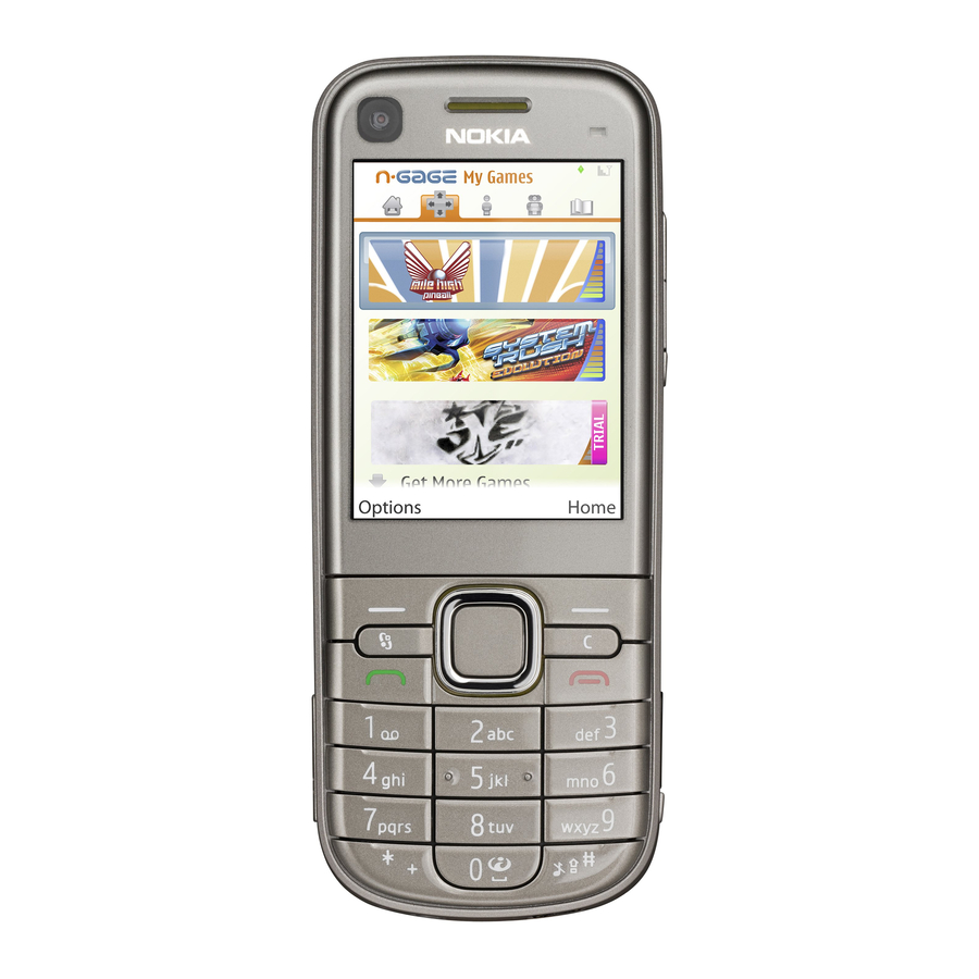
Table 3 Data ................................1–9 Table 4 Messaging ..............................1–9 Table 5 Music ................................1–9 Table 6 Navigation ..............................1–9 Table 7 Power .................................1–9 List of Figures Figure 1 View of RM-424............................1–5 Issue 1 COMPANY CONFIDENTIAL Page 1 –3 Copyright © 2009 Nokia. All rights reserved. - Page 16 RM-424; RM-564 General Information (This page left intentionally blank.) Page 1 –4 COMPANY CONFIDENTIAL Issue 1 Copyright © 2009 Nokia. All rights reserved.
-
Page 17: Product Selection
S60, which brings desktop-like Web browsing experience to mobile devices. RM-424 also supports MIDP Java 2.0, providing a good platform for compelling 3rd party applications. Figure 1 View of RM-424 Issue 1 COMPANY CONFIDENTIAL Page 1 –5 Copyright © 2009 Nokia. All rights reserved. -
Page 18: Product Features And Sales Package
• Speech codec support for AMR-WB, AMR, FR, EFR • Stereo speaker • RDS FM Radio Productivity Context management • OMA DRM version 2.0 • PIM (Calendar + Contacts + Active Notes) Page 1 –6 COMPANY CONFIDENTIAL Issue 1 Copyright © 2009 Nokia. All rights reserved. -
Page 19: Product And Module List
• Audio message reader for text messages and E-mail • VoIP calls Add-on software framework • Symbian OS 9.3 • Nokia Series 60, 3rd edition, feature pack 3.2 • Java: MIDP2.0 Additional features • City compass to support easy pedestrian routing and guidance •... -
Page 20: Mobile Enhancements
CK-300 (BT & plug-in) CK-600 FM transmitter CA-300 Holder CR-39 CR-82 CR-99 Mobile charger DC-4 Mobile holder easy mount HH-12 HH-17 Plug-in car handsfree HF-200 HF-300 HF-310 HF-510 Page 1 –8 COMPANY CONFIDENTIAL Issue 1 Copyright © 2009 Nokia. All rights reserved. -
Page 21: Table 3 Data
Music speakers MD-6 MD-8 Table 6 Navigation Enhancement Type Wireless GPS module LD-3W LD-4W Table 7 Power Enhancement Type Battery 1050mAh Li-ion BP-6MT Charger adapter DT-14 Issue 1 COMPANY CONFIDENTIAL Page 1 –9 Copyright © 2009 Nokia. All rights reserved. -
Page 22: Technical Specifications
GSM1800: 1710 - 1785 MHz GSM1900: 1850 - 1910 MHz WCDMA VIII (900): 880 - 915 MHz WCDMA II (1900): 1850-1910MHz WCDMA I (2100): 1920 - 1980 MHz Page 1 –10 COMPANY CONFIDENTIAL Issue 1 Copyright © 2009 Nokia. All rights reserved. -
Page 23: Battery Endurance
Capacity (mAh) Talk time Stand-by BP-6MT 1050 Up to 7.1 h (GSM) Up to 525 h (GSM) Up to 4.3 h (WCDMA) Up to 404 h (WCDMA) Issue 1 COMPANY CONFIDENTIAL Page 1 –11 Copyright © 2009 Nokia. All rights reserved. -
Page 24: Environmental Conditions
The standard for electrostatic discharge is IEC 61000-4-2, and this device fulfils level 4 requirements. RoHS This device uses RoHS compliant components and lead-free soldering process. Page 1 –12 COMPANY CONFIDENTIAL Issue 1 Copyright © 2009 Nokia. All rights reserved. - Page 25 Nokia Customer Care 2 — Service Tools and Service Concepts Issue 1 COMPANY CONFIDENTIAL Page 2 –1 Copyright © 2009 Nokia. All rights reserved.
- Page 26 RM-424; RM-564 Service Tools and Service Concepts (This page left intentionally blank.) Page 2 –2 COMPANY CONFIDENTIAL Issue 1 Copyright © 2009 Nokia. All rights reserved.
-
Page 27: Table Of Contents
CA-89DS ..............................2–17 DAU-9S ................................ 2–18 PCS-1 ................................2–18 XCS-4 ................................2–18 XRS-6................................2–19 Service concepts ..............................2–19 POS (Point of Sale) flash concept ........................2–19 Issue 1 COMPANY CONFIDENTIAL Page 2 –3 Copyright © 2009 Nokia. All rights reserved. - Page 28 Figure 11 RF testing / BB tuning concept ......................2–26 Figure 12 Service concept for RF testing and RF/BB tuning ................2–28 Figure 13 RF testing concept with RF coupler ....................2–29 Page 2 –4 COMPANY CONFIDENTIAL Issue 1 Copyright © 2009 Nokia. All rights reserved.
-
Page 29: Service Tools
RJ-230 is a soldering jig used for soldering and as a rework jig for the engine module. SA-131 RF coupler SA-131 is a generic device for GPS testing. It is used together with SS-62. Issue 1 COMPANY CONFIDENTIAL Page 2 –5 Copyright © 2009 Nokia. All rights reserved. -
Page 30: Using Sa-131 Gps Rf Coupler With Rm-424
High Using SA-131 GPS RF coupler with RM-424 Use the following basic SA-131 setup for RM-424: • 1575.520152 MHz • -110dbm • 20db fixed RF attenuator Page 2 –6 COMPANY CONFIDENTIAL Issue 1 Copyright © 2009 Nokia. All rights reserved. - Page 31 And use the following settings for the SA-131: • Base setting: 2 • Sledge setting: 2 • Frame setting: A1 • Coupler setting: A2 • Direction: Down Figure 2 Base setting for SA-131 Issue 1 COMPANY CONFIDENTIAL Page 2 –7 Copyright © 2009 Nokia. All rights reserved.
-
Page 32: Rework Jigs And Stencils
RJ-160 Rework jig RJ-160 is a rework jig used when servicing the WCDMA duplexer (Z7540). It is used together with the ST-55 stencil. Page 2 –8 COMPANY CONFIDENTIAL Issue 1 Copyright © 2009 Nokia. All rights reserved. - Page 33 It is used together with rework jig RJ-73. ST-40 Rework stencil ST-40 is a rework stencil that is used with the RJ-93 rework jig to service the Front End Module (N7520). Issue 1 COMPANY CONFIDENTIAL Page 2 –9 Copyright © 2009 Nokia. All rights reserved.
-
Page 34: General Tools
Universal power supply for FPS-21; included in the FPS-21 sales package. Also available as a separate spare part. Input 100V…230V 50Hz…60Hz, output voltage of 12 V and output current up to 3 A. Page 2 –10 COMPANY CONFIDENTIAL Issue 1 Copyright © 2009 Nokia. All rights reserved. - Page 35 4 Connect an FBUS cable (if necessary). 5 Start Phoenix service software. Note: Phoenix enables CU-4 regulators via USB when it is started. Reconnecting the power supply requires a Phoenix restart. Issue 1 COMPANY CONFIDENTIAL Page 2 –11 Copyright © 2009 Nokia. All rights reserved.
- Page 36 • Power Supply with 5 country specific cords • USB cable Note: FPS-21 is substitute FPS-10 if FPS-10 has not been set Note: FPS-10 is not available anymore. Page 2 –12 COMPANY CONFIDENTIAL Issue 1 Copyright © 2009 Nokia. All rights reserved.
-
Page 37: Fps-21
WCDMA network, a shield box is needed in all testing, tuning and fault finding which requires WCDMA RF signal. The shield box is not an active device, it contains only passive filtering components for RF attenuation. Issue 1 COMPANY CONFIDENTIAL Page 2 –13 Copyright © 2009 Nokia. All rights reserved. - Page 38 January 2009. For all new parts needing solder paste support after January 1, 2009, please contact your solder machine manufacturer for the universal solutions for solder paste application for rework purposes. Page 2 –14 COMPANY CONFIDENTIAL Issue 1 Copyright © 2009 Nokia. All rights reserved.
- Page 39 SRT-6 Opening tool SRT-6 is used to open phone covers. Note: The SRT-6 is included in the Nokia Standard Toolkit. SS-100 Camera removal tool The camera removal tool SS-100 is used to remove/attach a camera module from/to the camera socket of the phone PWB.
-
Page 40: Cables
USB cable The CA-31D USB cable is used to connect FPS-10 or FPS-11 to a PC. It is included in the FPS-10 and FPS-11 sales packages. Page 2 –16 COMPANY CONFIDENTIAL Issue 1 Copyright © 2009 Nokia. All rights reserved. -
Page 41: Ca-35S
Attenuation Rx/Tx GSM850/900 0.2...0.3 dB GSM1800/1900 0.3...0.4 dB WCDMA900 0.2...0.3 dB WCDMA2100 0.3...0.4 dB CA-89DS Cable Provides VBAT and Flashbus connections to mobile device programming adapters. Issue 1 COMPANY CONFIDENTIAL Page 2 –17 Copyright © 2009 Nokia. All rights reserved. -
Page 42: Dau-9S
XCS-4 Modular cable XCS-4 is a shielded (one specially shielded conductor) modular cable for flashing and service purposes. Page 2 –18 COMPANY CONFIDENTIAL Issue 1 Copyright © 2009 Nokia. All rights reserved. -
Page 43: Service Concepts
POS (Point of Sale) flash concept Figure 4 POS flash concept Type Description Product specific tools BP-6MT Battery Other tools FLS-5 POS flash dongle PC with Phoenix service software Issue 1 COMPANY CONFIDENTIAL Page 2 –19 Copyright © 2009 Nokia. All rights reserved. -
Page 44: Flash Concept With Fps-10
Other devices FPS-10 Flash prommer box PKD-1/PK-1 SW security device SS-46 Interface adapter PC with Phoenix service software Cables XCS-4 Modular cable CA-35S Power cable USB cable Page 2 –20 COMPANY CONFIDENTIAL Issue 1 Copyright © 2009 Nokia. All rights reserved. -
Page 45: Flash Concept With Fps-21
Other devices FPS-21 Flash prommer box AC-35 Power supply PK-1/PKD-1 SW security device SS-46 Interface adapter PC with Phoenix service software Cables CA-89DS Service cable USB cable Issue 1 COMPANY CONFIDENTIAL Page 2 –21 Copyright © 2009 Nokia. All rights reserved. -
Page 46: Flash Concept With Fps-10
SW security device SS-62 Flash adapter base SX-4 Smart card PC with Phoenix service software Cables PCS-1 Power cable XCS-4 Modular cable Standard USB cable USB cable Page 2 –22 COMPANY CONFIDENTIAL Issue 1 Copyright © 2009 Nokia. All rights reserved. -
Page 47: Flash Concept With Fps-21
Flash adapter base SX-4 Smart card (for DCT-4 generation mobile device programming) PC with Phoenix service software Cables PCS-1 Power cable CA-89DS Service cable Standard USB cable Issue 1 COMPANY CONFIDENTIAL Page 2 –23 Copyright © 2009 Nokia. All rights reserved. -
Page 48: Module Jig Service Concept
Smart card PC with Phoenix service software Measurement equipment Cables CA-58RS RF service cable (product-specific adapter cable) PCS-1 DC power cable XCS-4 Modular cable XRS-6 RF cable Page 2 –24 COMPANY CONFIDENTIAL Issue 1 Copyright © 2009 Nokia. All rights reserved. -
Page 49: Rf Testing Concept With Rf Coupler
CU-4 Control unit SX-4 Smart card FPS-10 Flash prommer box PKD-1/PK-1 SW security device SS-62 Flash adapter base Measurement equipment PC with Phoenix service software Cables Issue 1 COMPANY CONFIDENTIAL Page 2 –25 Copyright © 2009 Nokia. All rights reserved. -
Page 50: Rf Testing / Bb Tuning Concept
Product specific tools FS-97 Flash adapter SA-157 RF coupler Other tools CU-4 Control unit PKD-1/PK-1 SW security device SS-62 Flash adapter base SX-4 Smart card Measurement equipment Page 2 –26 COMPANY CONFIDENTIAL Issue 1 Copyright © 2009 Nokia. All rights reserved. -
Page 51: Bb/Rf Tuning Concept With Module Jig
Product specific tools MJ-191 Module jig Other tools CU-4 Control unit PKD-1 SW security device SX-4 Smart card PC with Phoenix service software Smart card reader Issue 1 COMPANY CONFIDENTIAL Page 2 –27 Copyright © 2009 Nokia. All rights reserved. -
Page 52: Bluetooth Testing Concept With
Control unit SS-62 Flash adapter base PK-1 SW security device SX-4 Smart card SB-6 Bluetooth test and interface box Smart card reader PC with Phoenix service software Page 2 –28 COMPANY CONFIDENTIAL Issue 1 Copyright © 2009 Nokia. All rights reserved. -
Page 53: Gps Testing Concept With Gps Rf Coupler
GPS RF coupler Other devices CU-4 Control unit SX-4 Smart card JXS-1 RF shield box PKD-1/PK-1 SW security device SS-62 Flash adapter base Smart card reader Issue 1 COMPANY CONFIDENTIAL Page 2 –29 Copyright © 2009 Nokia. All rights reserved. - Page 54 PC with Phoenix service software Cables CA-58RS RF service cable (product-specific adapter cable) PCS-1 Power cable DAU-9S MBUS cable XRS-6 RF cable 20dB attenuator Interface cable USB cable Page 2 –30 COMPANY CONFIDENTIAL Issue 1 Copyright © 2009 Nokia. All rights reserved.
- Page 55 Nokia Customer Care 3 — BB Troubleshooting and Manual Tuning Guide Issue 1 COMPANY CONFIDENTIAL Page 3 –1 Copyright © 2009 Nokia. All rights reserved.
- Page 56 RM-424; RM-564 BB Troubleshooting and Manual Tuning Guide (This page left intentionally blank.) Page 3 –2 COMPANY CONFIDENTIAL Issue 1 Copyright © 2009 Nokia. All rights reserved.
- Page 57 Internal microphone troubleshooting ......................3–55 Internal microphone troubleshooting....................3–55 EANC microphone testing ......................... 3–55 Internal handsfree (IHF) troubleshooting....................3–58 External earpiece troubleshooting....................... 3–58 External microphone troubleshooting......................3–60 Issue 1 COMPANY CONFIDENTIAL Page 3 –3 Copyright © 2009 Nokia. All rights reserved.
- Page 58 Figure 31 EANC error microphone ........................3–61 Figure 32 EANC reference microphone......................3–62 Figure 33 Audio uplink microphones ........................ 3–62 Figure 34 Test points in Bluetooth-FM ASIC circuit ..................3–70 Page 3 –4 COMPANY CONFIDENTIAL Issue 1 Copyright © 2009 Nokia. All rights reserved.
-
Page 59: Baseband Self Tests In Phoenix
Always start the troubleshooting procedure by running the Phoenix self tests. If a test fails, please follow the diagram below. Dead or jammed device troubleshooting. If the phone is dead and you cannot perform the self tests, go to Issue 1 COMPANY CONFIDENTIAL Page 3 –5 Copyright © 2009 Nokia. All rights reserved. - Page 60 RM-424; RM-564 BB Troubleshooting and Manual Tuning Guide Troubleshooting flow Page 3 –6 COMPANY CONFIDENTIAL Issue 1 Copyright © 2009 Nokia. All rights reserved.
-
Page 61: Power And Charging Troubleshooting
RM-424; RM-564 BB Troubleshooting and Manual Tuning Guide Power and charging troubleshooting Dead or jammed device troubleshooting Troubleshooting flow - Page 1 of 2 Issue 1 COMPANY CONFIDENTIAL Page 3 –7 Copyright © 2009 Nokia. All rights reserved. - Page 62 RM-424; RM-564 BB Troubleshooting and Manual Tuning Guide Troubleshooting flow - Page 2 of 2 Page 3 –8 COMPANY CONFIDENTIAL Issue 1 Copyright © 2009 Nokia. All rights reserved.
-
Page 63: Power Key Troubleshooting
RM-424; RM-564 BB Troubleshooting and Manual Tuning Guide Power key troubleshooting Troubleshooting flow Issue 1 COMPANY CONFIDENTIAL Page 3 –9 Copyright © 2009 Nokia. All rights reserved. -
Page 64: General Voltage Checking Troubleshooting
RM-424; RM-564 BB Troubleshooting and Manual Tuning Guide General voltage checking troubleshooting Troubleshooting flow - Page 1 of 2 Page 3 –10 COMPANY CONFIDENTIAL Issue 1 Copyright © 2009 Nokia. All rights reserved. - Page 65 RM-424; RM-564 BB Troubleshooting and Manual Tuning Guide Troubleshooting flow - Page 2 of 2 Issue 1 COMPANY CONFIDENTIAL Page 3 –11 Copyright © 2009 Nokia. All rights reserved.
-
Page 66: General Power Checking
RAPU version & SW VOUT Pearl/Gazoo Video switch VCAM_2V8 N1401 Camera Disabled in sleep VCAM_1V8 N1402 1.800 Camera Disabled in sleep VMEM Pearl/Gazoo microSD Disabled in sleep Page 3 –12 COMPANY CONFIDENTIAL Issue 1 Copyright © 2009 Nokia. All rights reserved. -
Page 67: Battery Current Measuring Fault Troubleshooting
RM-424; RM-564 BB Troubleshooting and Manual Tuning Guide Battery current measuring fault troubleshooting Troubleshooting flow Issue 1 COMPANY CONFIDENTIAL Page 3 –13 Copyright © 2009 Nokia. All rights reserved. -
Page 68: Charging Troubleshooting
RM-424; RM-564 BB Troubleshooting and Manual Tuning Guide Charging troubleshooting Troubleshooting flow Page 3 –14 COMPANY CONFIDENTIAL Issue 1 Copyright © 2009 Nokia. All rights reserved. -
Page 69: Clocking Troubleshooting
RM-424; RM-564 BB Troubleshooting and Manual Tuning Guide Clocking troubleshooting Troubleshooting flow Issue 1 COMPANY CONFIDENTIAL Page 3 –15 Copyright © 2009 Nokia. All rights reserved. -
Page 70: Interface Troubleshooting
RM-424; RM-564 BB Troubleshooting and Manual Tuning Guide Interface troubleshooting Flash programming fault troubleshooting Troubleshooting flow - Page 1 of 2 Page 3 –16 COMPANY CONFIDENTIAL Issue 1 Copyright © 2009 Nokia. All rights reserved. - Page 71 BB Troubleshooting and Manual Tuning Guide Troubleshooting flow - Page 2 of 2 Figure 14 Flashing pic 1. Take single trig measurement for the rise of the BSI signal Issue 1 COMPANY CONFIDENTIAL Page 3 –17 Copyright © 2009 Nokia. All rights reserved.
- Page 72 RM-424; RM-564 BB Troubleshooting and Manual Tuning Guide Figure 15 Flashing pic 2. Take single trig measurement for the rise of the BSI signal Page 3 –18 COMPANY CONFIDENTIAL Issue 1 Copyright © 2009 Nokia. All rights reserved.
-
Page 73: Sim Card Troubleshooting
RM-424; RM-564 BB Troubleshooting and Manual Tuning Guide SIM card troubleshooting Troubleshooting flow Issue 1 COMPANY CONFIDENTIAL Page 3 –19 Copyright © 2009 Nokia. All rights reserved. - Page 74 RM-424; RM-564 BB Troubleshooting and Manual Tuning Guide Page 3 –20 COMPANY CONFIDENTIAL Issue 1 Copyright © 2009 Nokia. All rights reserved.
-
Page 75: Microsd Card Troubleshooting
RM-424; RM-564 BB Troubleshooting and Manual Tuning Guide MicroSD card troubleshooting Troubleshooting flow Issue 1 COMPANY CONFIDENTIAL Page 3 –21 Copyright © 2009 Nokia. All rights reserved. -
Page 76: Usb Data Interface Troubleshooting
RM-424; RM-564 BB Troubleshooting and Manual Tuning Guide USB data interface troubleshooting Troubleshooting flow - Page 1 of 2 Page 3 –22 COMPANY CONFIDENTIAL Issue 1 Copyright © 2009 Nokia. All rights reserved. -
Page 77: Tv-Out Troubleshooting
A composite video monitor (TV) can be connected to a TV-out connector. The TV-out connection supports PAL and NTSC video standards. Video signal is connected to AV-connector pin 3. Issue 1 COMPANY CONFIDENTIAL Page 3 –23 Copyright © 2009 Nokia. All rights reserved. - Page 78 RM-424; RM-564 BB Troubleshooting and Manual Tuning Guide Troubleshooting flow Page 3 –24 COMPANY CONFIDENTIAL Issue 1 Copyright © 2009 Nokia. All rights reserved.
-
Page 79: User Interface Troubleshooting
If the failure mode is not clear, start with the Keyboard test in Phoenix. In this phone the keyboard is connected to D2800 I/O pins. Troubleshooting flow Issue 1 COMPANY CONFIDENTIAL Page 3 –25 Copyright © 2009 Nokia. All rights reserved. -
Page 80: Keyboard, Side Keys And Indicator Led Troubleshooting
There is no image on the display. The display looks the same when the phone is on as it does when the phone is off. The backlight can be on in some cases. Page 3 –26 COMPANY CONFIDENTIAL Issue 1 Copyright © 2009 Nokia. All rights reserved. - Page 81 APE ID). 3. Proceed to the display fault troubleshooting flowchart. Phoenix to find the detailed fault mode. Use the Display Test tool in Issue 1 COMPANY CONFIDENTIAL Page 3 –27 Copyright © 2009 Nokia. All rights reserved.
-
Page 82: Display Fault Troubleshooting
RM-424; RM-564 BB Troubleshooting and Manual Tuning Guide Display fault troubleshooting Context The display module is an active matrix TFT panel including display controller. Page 3 –28 COMPANY CONFIDENTIAL Issue 1 Copyright © 2009 Nokia. All rights reserved. - Page 83 RM-424; RM-564 BB Troubleshooting and Manual Tuning Guide Troubleshooting flow Issue 1 COMPANY CONFIDENTIAL Page 3 –29 Copyright © 2009 Nokia. All rights reserved.
-
Page 84: Introduction To Display And Keyboard Backlight Troubleshooting
LED network can be enabled and disabled independently from Gazoo LedCR register or using Phoenix display test program. Display LEDs are located inside the display and keyboard LEDs are on the PWB. Page 3 –30 COMPANY CONFIDENTIAL Issue 1 Copyright © 2009 Nokia. All rights reserved. -
Page 85: Display Backlight Troubleshooting
RM-424; RM-564 BB Troubleshooting and Manual Tuning Guide Display backlight troubleshooting Troubleshooting flow Issue 1 COMPANY CONFIDENTIAL Page 3 –31 Copyright © 2009 Nokia. All rights reserved. -
Page 86: Ambient Light Sensor Troubleshooting And Re-Calibration
ALS is stable. The light quide of the ALS is located on the upper part of the phone’s front cover, right next to the secondary camera. Page 3 –32 COMPANY CONFIDENTIAL Issue 1 Copyright © 2009 Nokia. All rights reserved. - Page 87 5. If the component does not give any reading or the reading does not change when sensor is/is not covered, replace the part. Note: The ALS calibration procedure requires a reference phone with a calibrated ALS. Issue 1 COMPANY CONFIDENTIAL Page 3 –33 Copyright © 2009 Nokia. All rights reserved.
-
Page 88: Als Troubleshooting
RM-424; RM-564 BB Troubleshooting and Manual Tuning Guide ALS troubleshooting Troubleshooting flow Page 3 –34 COMPANY CONFIDENTIAL Issue 1 Copyright © 2009 Nokia. All rights reserved. -
Page 89: Calibrating Als
Calibration is done when the Co-efficient is equal to the co-efficient value calculated in step 6. Note: Decimal numbers should be used in the iteration to achieve adequate precision (e.g. 200.2455) Issue 1 COMPANY CONFIDENTIAL Page 3 –35 Copyright © 2009 Nokia. All rights reserved. -
Page 90: Accelerometer And Magnetometer Troubleshooting
If the illuminance values differ more than +- 10%, repeat the whole ALS calibration procedure. 10. To end the calibration, click Close. Accelerometer and magnetometer troubleshooting UI (map) features troubleshooting Page 3 –36 COMPANY CONFIDENTIAL Issue 1 Copyright © 2009 Nokia. All rights reserved. - Page 91 RM-424; RM-564 BB Troubleshooting and Manual Tuning Guide Accelerometer troubleshooting Magnetometer troubleshooting Issue 1 COMPANY CONFIDENTIAL Page 3 –37 Copyright © 2009 Nokia. All rights reserved.
-
Page 92: Gps Troubleshooting
BB Troubleshooting and Manual Tuning Guide GPS troubleshooting GPS antenna The GPS antenna is located on the A-side at the top of the phone. Figure 17 GPS antenna Page 3 –38 COMPANY CONFIDENTIAL Issue 1 Copyright © 2009 Nokia. All rights reserved. -
Page 93: Gps Layout And Basic Test Points
CW test. J6210 = GPS Ant J6211 = GPS Ant Gnd Issue 1 COMPANY CONFIDENTIAL Page 3 –39 Copyright © 2009 Nokia. All rights reserved. - Page 94 In order to probe GPS RF test points, inject 1575.52 MHz tone @ -50dBm at the GPS antenna test connector and select Receiver On, then probe the GPS RF test points as shown in the figure below. Compare RF levels with a known reference phone. Page 3 –40 COMPANY CONFIDENTIAL Issue 1 Copyright © 2009 Nokia. All rights reserved.
-
Page 95: Gps Settings For Phoenix
Use the following to test GPS using Phoenix. Steps 1. Start Phoenix service software. 2. From the File menu, select Scan Product and check that the correct product version is displayed. Issue 1 COMPANY CONFIDENTIAL Page 3 –41 Copyright © 2009 Nokia. All rights reserved. - Page 96 On will turn on all the RF sections of the ASIC and so all LDOs will be present. Turning Receiver Action Note: These checks are part of GPS basic checks troubleshooting (page 3–48) Figure 21 GPS Control dialog box Page 3 –42 COMPANY CONFIDENTIAL Issue 1 Copyright © 2009 Nokia. All rights reserved.
-
Page 97: Oscillator Test
Rx Control window, go to the Simple Tests section, select Oscillator Test and click Start. The Offset In the result will be returned and should be within the limits of +- 84Hz. Issue 1 COMPANY CONFIDENTIAL Page 3 –43 Copyright © 2009 Nokia. All rights reserved. -
Page 98: Receiver Self Test
Oscillator test to prolong and result in Phoenix timing out. If you are carrying out both of these tests, run the Oscillator Test first, after which you can run the Receiver Self Test. Page 3 –44 COMPANY CONFIDENTIAL Issue 1 Copyright © 2009 Nokia. All rights reserved. -
Page 99: Cw Test
GPS antenna test connector at a level of -110dBm and click Start. For Pin = -110dBm and negligible other losses, the expected result ranges are: • Galvanic 29.8dB to 38.1dB • Radiated 25.8dB to 38.1dB Issue 1 COMPANY CONFIDENTIAL Page 3 –45 Copyright © 2009 Nokia. All rights reserved. -
Page 100: Quick Test Window
Oscillator Test . It does not necessarily mean that Oscillator Test has failed, but carrying out the Oscillator Test (page 3–43), Receiver Self Test (page 3–44) CW Test (page 3–45) individually will give more valid results. Page 3 –46 COMPANY CONFIDENTIAL Issue 1 Copyright © 2009 Nokia. All rights reserved. -
Page 101: Gps Failure Troubleshooting
GPS troubleshooting is broken down into two parts: General GPS failure & GPS basic checks. The GPS failure troubleshooting flow can be followed and, where applicable, will feed into the basic checks troubleshooting flow. Issue 1 COMPANY CONFIDENTIAL Page 3 –47 Copyright © 2009 Nokia. All rights reserved. - Page 102 RM-424; RM-564 BB Troubleshooting and Manual Tuning Guide Troubleshooting flow Page 3 –48 COMPANY CONFIDENTIAL Issue 1 Copyright © 2009 Nokia. All rights reserved.
-
Page 103: Gps Basic Checks Troubleshooting
RM-424; RM-564 BB Troubleshooting and Manual Tuning Guide GPS basic checks troubleshooting Troubleshooting flow Issue 1 COMPANY CONFIDENTIAL Page 3 –49 Copyright © 2009 Nokia. All rights reserved. -
Page 104: Audio Troubleshooting
[dB] (fixed) 1 kHz sine output DC level [mVp-p] voltage [mVp- AV mic to AV ear HS_MIC HS_EAR_R and +21.3 and GND HS_EAR_L and Page 3 –50 COMPANY CONFIDENTIAL Issue 1 Copyright © 2009 Nokia. All rights reserved. - Page 105 Figure 27 AV mic to AV ear, single-ended loop measurement. 16 kHz lowpass filter is used to attenuate noise from the signal. The filter is optional. Issue 1 COMPANY CONFIDENTIAL Page 3 –51 Copyright © 2009 Nokia. All rights reserved.
- Page 106 Figure 28 AV mic to HP ear, single-ended loop measurement. 62.5 kHz lowpass filter is used to attenuate noise from the signal. The filter is optional. Figure 29 Ext microphone in Int handsfree out, single-ended loop measurement without filter. Page 3 –52 COMPANY CONFIDENTIAL Issue 1 Copyright © 2009 Nokia. All rights reserved.
- Page 107 Figure 30 Ext microphone in Int handsfree out, differential loop measurement with 8 kHz lowpass filter. The signal is measured differentially between the pads of B2102 or B2103. Issue 1 COMPANY CONFIDENTIAL Page 3 –53 Copyright © 2009 Nokia. All rights reserved.
-
Page 108: Internal Earpiece Troubleshooting
RM-424; RM-564 BB Troubleshooting and Manual Tuning Guide Internal earpiece troubleshooting Troubleshooting flow Page 3 –54 COMPANY CONFIDENTIAL Issue 1 Copyright © 2009 Nokia. All rights reserved. -
Page 109: Internal Microphone Troubleshooting
RM-424; RM-564 BB Troubleshooting and Manual Tuning Guide Internal microphone troubleshooting Internal microphone troubleshooting Troubleshooting flow Issue 1 COMPANY CONFIDENTIAL Page 3 –55 Copyright © 2009 Nokia. All rights reserved. -
Page 110: Eanc Microphone Testing
Audio Control window, activate E-ANC Microphone Test. 7. In the The IHF speakers emit a 1 kHz tone and the EANC microphones measure the sound level. Page 3 –56 COMPANY CONFIDENTIAL Issue 1 Copyright © 2009 Nokia. All rights reserved. - Page 111 It is recommended to run this test more than once and observe the results. There may be an electrical fault if a microphone gives exactly the same result each time. The test returns also PASS/FAIL information for both microphones. Issue 1 COMPANY CONFIDENTIAL Page 3 –57 Copyright © 2009 Nokia. All rights reserved.
-
Page 112: Internal Handsfree (Ihf) Troubleshooting
RM-424; RM-564 BB Troubleshooting and Manual Tuning Guide Internal handsfree (IHF) troubleshooting Troubleshooting flow Page 3 –58 COMPANY CONFIDENTIAL Issue 1 Copyright © 2009 Nokia. All rights reserved. -
Page 113: External Earpiece Troubleshooting
RM-424; RM-564 BB Troubleshooting and Manual Tuning Guide External earpiece troubleshooting Troubleshooting flow Issue 1 COMPANY CONFIDENTIAL Page 3 –59 Copyright © 2009 Nokia. All rights reserved. -
Page 114: External Microphone Troubleshooting
RM-424; RM-564 BB Troubleshooting and Manual Tuning Guide External microphone troubleshooting Troubleshooting flow Page 3 –60 COMPANY CONFIDENTIAL Issue 1 Copyright © 2009 Nokia. All rights reserved. -
Page 115: Acoustics Troubleshooting
The phone should be dry and clean, and no objects must be located in such a way that they close any of the holes. Figure 31 EANC error microphone Issue 1 COMPANY CONFIDENTIAL Page 3 –61 Copyright © 2009 Nokia. All rights reserved. - Page 116 RM-424; RM-564 BB Troubleshooting and Manual Tuning Guide Figure 32 EANC reference microphone Figure 33 Audio uplink microphones Page 3 –62 COMPANY CONFIDENTIAL Issue 1 Copyright © 2009 Nokia. All rights reserved.
-
Page 117: Earpiece Troubleshooting
RM-424; RM-564 BB Troubleshooting and Manual Tuning Guide Earpiece troubleshooting Troubleshooting flow Issue 1 COMPANY CONFIDENTIAL Page 3 –63 Copyright © 2009 Nokia. All rights reserved. -
Page 118: Ihf Troubleshooting
RM-424; RM-564 BB Troubleshooting and Manual Tuning Guide IHF troubleshooting Troubleshooting flow Page 3 –64 COMPANY CONFIDENTIAL Issue 1 Copyright © 2009 Nokia. All rights reserved. -
Page 119: Eanc Error Microphone Troubleshooting
RM-424; RM-564 BB Troubleshooting and Manual Tuning Guide EANC error microphone troubleshooting Troubleshooting flow Issue 1 COMPANY CONFIDENTIAL Page 3 –65 Copyright © 2009 Nokia. All rights reserved. -
Page 120: Eanc Reference Microphone Troubleshooting
RM-424; RM-564 BB Troubleshooting and Manual Tuning Guide EANC reference microphone troubleshooting Troubleshooting flow Page 3 –66 COMPANY CONFIDENTIAL Issue 1 Copyright © 2009 Nokia. All rights reserved. -
Page 121: Uplink Microphone Troubleshooting
RM-424; RM-564 BB Troubleshooting and Manual Tuning Guide Uplink microphone troubleshooting Troubleshooting flow Issue 1 COMPANY CONFIDENTIAL Page 3 –67 Copyright © 2009 Nokia. All rights reserved. -
Page 122: Vibra Troubleshooting
Open circuit solder joints or Replacement of Bluetooth/FM ASIC/ Bluetooth on phone component failure of BTH/ module. user interface. FM ASIC/module BB ASICs or SMD components. Page 3 –68 COMPANY CONFIDENTIAL Issue 1 Copyright © 2009 Nokia. All rights reserved. -
Page 123: Bluetooth And Fm Radio Component Placement
FM audio through headset. Bluetooth and FM radio component placement The figure below shows the test points for BTHFMRDS2.2D in RM-424. Issue 1 COMPANY CONFIDENTIAL Page 3 –69 Copyright © 2009 Nokia. All rights reserved. - Page 124 RM-424; RM-564 BB Troubleshooting and Manual Tuning Guide Figure 34 Test points in Bluetooth-FM ASIC circuit Page 3 –70 COMPANY CONFIDENTIAL Issue 1 Copyright © 2009 Nokia. All rights reserved.
-
Page 125: Bluetooth And Fm Radio Module Troubleshooting
RM-424; RM-564 BB Troubleshooting and Manual Tuning Guide Bluetooth and FM radio module troubleshooting Troubleshooting flow Issue 1 COMPANY CONFIDENTIAL Page 3 –71 Copyright © 2009 Nokia. All rights reserved. -
Page 126: Baseband Manual Tuning Guide
Note: USB flashing does not work for a dead BB5 phone. • Create a request file. • Send the file to Nokia by e-mail. Use the following addresses depending on your location: • APAC: sydney.service@nokia.com • CHINA: repair.ams@nokia.com • E&A: salo.repair@nokia.com •... - Page 127 Flash Type must be set to Phone as Manufactured. To continue, click Start. Progress bars and messages on the screen show actions during phone programming, please wait. Issue 1 COMPANY CONFIDENTIAL Page 3 –73 Copyright © 2009 Nokia. All rights reserved.
- Page 128 Phoenix , choose File→Scan Product . To connect the phone with ii Choose Tools→Certificate Restore . iii To choose a location for the request file, click Browse. Page 3 –74 COMPANY CONFIDENTIAL Issue 1 Copyright © 2009 Nokia. All rights reserved.
- Page 129 Request file, click Start. To create the vi When the file for certificate restore has been created, send it to Nokia as an e-mail attachment. 3. Restore certificate. For this procedure, you must supply +12 V to CU-4 from an external power supply.
- Page 130 To write the file to phone, click Start. Next actions Phoenix tuning functions. After a successful rewrite, you must retune the phone completely by using Important: Perform all tunings: RF, BB, and UI. Page 3 –76 COMPANY CONFIDENTIAL Issue 1 Copyright © 2009 Nokia. All rights reserved.
-
Page 131: Energy Management Calibration
Write and/or repeat the procedure again. Energy Management Calibration window. 10. To end the procedure, close the Issue 1 COMPANY CONFIDENTIAL Page 3 –77 Copyright © 2009 Nokia. All rights reserved. - Page 132 RM-424; RM-564 BB Troubleshooting and Manual Tuning Guide (This page left intentionally blank.) Page 3 –78 COMPANY CONFIDENTIAL Issue 1 Copyright © 2009 Nokia. All rights reserved.
- Page 133 Nokia Customer Care 4 — RF Troubleshooting Issue 1 COMPANY CONFIDENTIAL Page 4 –1 Copyright © 2009 Nokia. All rights reserved.
- Page 134 RM-424; RM-564 RF Troubleshooting (This page left intentionally blank.) Page 4 –2 COMPANY CONFIDENTIAL Issue 1 Copyright © 2009 Nokia. All rights reserved.
- Page 135 Figure 45 Test points for voltage checking ...................... 4–26 Figure 46 Component reference schematics ....................4–29 Figure 47 Main antenna............................4–30 Figure 48 Antenna contacts ..........................4–31 Issue 1 COMPANY CONFIDENTIAL Page 4 –3 Copyright © 2009 Nokia. All rights reserved.
- Page 136 RM-424; RM-564 RF Troubleshooting (This page left intentionally blank.) Page 4 –4 COMPANY CONFIDENTIAL Issue 1 Copyright © 2009 Nokia. All rights reserved.
-
Page 137: General Rf Troubleshooting
RF shielded environment, testing at frequencies of nearby base stations should be avoided. Level of repair The scope of this guideline is to verify functionality of the cellular RF block without removing RF shield. Issue 1 COMPANY CONFIDENTIAL Page 4 –5 Copyright © 2009 Nokia. All rights reserved. -
Page 138: Rf Key Components
RM-424; RM-564 RF Troubleshooting RF key components Figure 35 RF key components Page 4 –6 COMPANY CONFIDENTIAL Issue 1 Copyright © 2009 Nokia. All rights reserved. -
Page 139: Auto Tuning
3. Set the loss between CMU200 and the phone. (Total loss = cable + jig) 4. Go to auto tuning by selecting Tuning (Alt_U)→Auto-tune (Alt_A) from the menu. 5. Start auto tuning by clicking the Tune button. Issue 1 COMPANY CONFIDENTIAL Page 4 –7 Copyright © 2009 Nokia. All rights reserved. -
Page 140: Self Test Troubleshooting
Self tests are recommended to be made when phone is in jig and a 50Ω load connected to the RF connector. Otherwise power tests may fail depending on antenna load Page 4 –8 COMPANY CONFIDENTIAL Issue 1 Copyright © 2009 Nokia. All rights reserved. - Page 141 RM-424; RM-564 RF Troubleshooting Troubleshooting flow Issue 1 COMPANY CONFIDENTIAL Page 4 –9 Copyright © 2009 Nokia. All rights reserved.
-
Page 142: Receiver Troubleshooting
The reading should reflect the level of the signal generator (minus losses) ±5dB. When varying the level in the range -30 to -102dBm the reading should then follow within ±5dB. Page 4 –10 COMPANY CONFIDENTIAL Issue 1 Copyright © 2009 Nokia. All rights reserved. -
Page 143: Gsm Receiver Troubleshooting Flowchart
RM-424; RM-564 RF Troubleshooting GSM receiver troubleshooting flowchart Troubleshooting flow Issue 1 COMPANY CONFIDENTIAL Page 4 –11 Copyright © 2009 Nokia. All rights reserved. -
Page 144: Wcdma Rx Chain Activation For Manual Measurement
4. Click Start to activate the settings. If the settings are changed later on (for example, change of channel) you have to click Stop and Start again. Page 4 –12 COMPANY CONFIDENTIAL Issue 1 Copyright © 2009 Nokia. All rights reserved. -
Page 145: Wcdma Rssi Measurement
2. In the RX Power measurement window, select: • Mode: RSSI • Continuous mode 3. Click Start to perform the measurement. Note: WCDMA RSSI measurement is accurate only with WCDMA modulated signal. Issue 1 COMPANY CONFIDENTIAL Page 4 –13 Copyright © 2009 Nokia. All rights reserved. -
Page 146: Wcdma Receiver Troubleshooting Flowchart
RM-424; RM-564 RF Troubleshooting WCDMA receiver troubleshooting flowchart Troubleshooting flow Page 4 –14 COMPANY CONFIDENTIAL Issue 1 Copyright © 2009 Nokia. All rights reserved. -
Page 147: Transmitter Troubleshooting
1. Set the phone to local mode. 2. In Phoenix, select Testing→GSM→Rf Controls . The RF Controls window opens. Figure 40 Phoenix RF Controls window 3. Make the following settings: Issue 1 COMPANY CONFIDENTIAL Page 4 –15 Copyright © 2009 Nokia. All rights reserved. - Page 148 High Tx Power Level 4. Check the basic TX parameters, using a communication analyser (e.g. CMU200). • Power • Phase error • Modulation • Switching spectrum Page 4 –16 COMPANY CONFIDENTIAL Issue 1 Copyright © 2009 Nokia. All rights reserved.
- Page 149 RM-424; RM-564 RF Troubleshooting Figure 41 Typical readings 5. Change the power level in RF controls window and make sure the power reading follows accordingly. Issue 1 COMPANY CONFIDENTIAL Page 4 –17 Copyright © 2009 Nokia. All rights reserved.
- Page 150 You can troubleshoot the GSM transmitter for each GSM band separately, one band at a time. If you want to troubleshoot GSM850, GSM1800 or GSM1900, change the band in the RF controls window and set the communication analyser accordingly. Page 4 –18 COMPANY CONFIDENTIAL Issue 1 Copyright © 2009 Nokia. All rights reserved.
-
Page 151: Gsm Transmitter Troubleshooting Flowchart
RM-424; RM-564 RF Troubleshooting GSM transmitter troubleshooting flowchart Troubleshooting flow Issue 1 COMPANY CONFIDENTIAL Page 4 –19 Copyright © 2009 Nokia. All rights reserved. -
Page 152: Wcdma Transmitter Troubleshooting
9400 WCDMA VIII 2788 4. Make the following general settings (the same values for all bands). Note that Max power limit is not checked by default. Page 4 –20 COMPANY CONFIDENTIAL Issue 1 Copyright © 2009 Nokia. All rights reserved. - Page 153 If settings are changed (eg. new channel selected), you have to click RF Stop and Send again. 6. Check the basic TX parameters using a communication analyser (e.g. CMU200). Issue 1 COMPANY CONFIDENTIAL Page 4 –21 Copyright © 2009 Nokia. All rights reserved.
- Page 154 RM-424; RM-564 RF Troubleshooting Figure 43 Typical readings Page 4 –22 COMPANY CONFIDENTIAL Issue 1 Copyright © 2009 Nokia. All rights reserved.
-
Page 155: Wcdma Transmitter Troubleshooting Flowchart
RM-424; RM-564 RF Troubleshooting WCDMA transmitter troubleshooting flowchart Troubleshooting flow Issue 1 COMPANY CONFIDENTIAL Page 4 –23 Copyright © 2009 Nokia. All rights reserved. -
Page 156: Troubleshooting With Rf-Shield Removed
Supply input to DC/DC conv C7527 3.7V (Vbattery) Note: When using settings as shown in the following Tx Control window, the result at TP4 should be 3.1V. Page 4 –24 COMPANY CONFIDENTIAL Issue 1 Copyright © 2009 Nokia. All rights reserved. - Page 157 RM-424; RM-564 RF Troubleshooting Figure 44 Phoenix WCDMA Tx Control window settings Issue 1 COMPANY CONFIDENTIAL Page 4 –25 Copyright © 2009 Nokia. All rights reserved.
- Page 158 RM-424; RM-564 RF Troubleshooting Figure 45 Test points for voltage checking Page 4 –26 COMPANY CONFIDENTIAL Issue 1 Copyright © 2009 Nokia. All rights reserved.
-
Page 159: Vctcxo Troubleshooting
This table shows the components used for the different bands. It can be used as a reference when troubleshooting which components may or may not be faulty. Issue 1 COMPANY CONFIDENTIAL Page 4 –27 Copyright © 2009 Nokia. All rights reserved. - Page 160 Z7544 X means that the component is used for the band in the current column. For further reference, see Component reference schematics on the following page. Page 4 –28 COMPANY CONFIDENTIAL Issue 1 Copyright © 2009 Nokia. All rights reserved.
- Page 161 RM-424; RM-564 RF Troubleshooting RF block schematics Figure 46 Component reference schematics Issue 1 COMPANY CONFIDENTIAL Page 4 –29 Copyright © 2009 Nokia. All rights reserved.
-
Page 162: Antenna
The main antenna has one feed pad for GSM and WCDMA, one feed pad for BT, one contact to Mutant switch and two ground pads. Check that GND and feed pads take proper contact to the C-clips on the main PWB. Page 4 –30 COMPANY CONFIDENTIAL Issue 1 Copyright © 2009 Nokia. All rights reserved. - Page 163 RM-424; RM-564 RF Troubleshooting Figure 48 Antenna contacts Issue 1 COMPANY CONFIDENTIAL Page 4 –31 Copyright © 2009 Nokia. All rights reserved.
- Page 164 RM-424; RM-564 RF Troubleshooting (This page left intentionally blank.) Page 4 –32 COMPANY CONFIDENTIAL Issue 1 Copyright © 2009 Nokia. All rights reserved.
- Page 165 Nokia Customer Care 5 — Camera Module Troubleshooting Issue 1 COMPANY CONFIDENTIAL Page 5 –1 Copyright © 2009 Nokia. All rights reserved.
- Page 166 RM-424; RM-564 Camera Module Troubleshooting (This page left intentionally blank.) Page 5 –2 COMPANY CONFIDENTIAL Issue 1 Copyright © 2009 Nokia. All rights reserved.
- Page 167 Secondary (front) camera troubleshooting ...................... 5–11 Evaluating videocall picture quality from secondary camera..............5–11 Secondary camera hardware troubleshooting ................... 5–11 Secondary camera bad image quality troubleshooting................5–12 Issue 1 COMPANY CONFIDENTIAL Page 5 –3 Copyright © 2009 Nokia. All rights reserved.
- Page 168 RM-424; RM-564 Camera Module Troubleshooting (This page left intentionally blank.) Page 5 –4 COMPANY CONFIDENTIAL Issue 1 Copyright © 2009 Nokia. All rights reserved.
-
Page 169: Main (Back) Camera Troubleshooting
• Analyse the picture from your PC monitor, full colour setting is recommended • If possible, compare with a picture of the same motive taken with a similar Nokia device • If camera has auto focus: Remember that the white focussing frame which appears when the camera button is pressed halfway down, must turn green for auto focus lock. -
Page 170: Main Camera Troubleshooting
RM-424; RM-564 Camera Module Troubleshooting Main camera troubleshooting Troubleshooting flow Page 5 –6 COMPANY CONFIDENTIAL Issue 1 Copyright © 2009 Nokia. All rights reserved. -
Page 171: Main Camera Baseband Troubleshooting
RM-424; RM-564 Camera Module Troubleshooting Main camera baseband troubleshooting Troubleshooting flow Issue 1 COMPANY CONFIDENTIAL Page 5 –7 Copyright © 2009 Nokia. All rights reserved. -
Page 172: Main Camera No Recognizable Viewfinder Image Troubleshooting
RM-424; RM-564 Camera Module Troubleshooting Main camera no recognizable viewfinder image troubleshooting Troubleshooting flow Page 5 –8 COMPANY CONFIDENTIAL Issue 1 Copyright © 2009 Nokia. All rights reserved. -
Page 173: Main Camera Bad Image Quality Troubleshooting
RM-424; RM-564 Camera Module Troubleshooting Main camera bad image quality troubleshooting Troubleshooting flow Issue 1 COMPANY CONFIDENTIAL Page 5 –9 Copyright © 2009 Nokia. All rights reserved. -
Page 174: Camera Flash And Privacy Indicator Troubleshooting
Camera Module Troubleshooting Camera flash and privacy indicator troubleshooting Context Note: Before checking flash functionality, make sure that the main camera is working ok. Troubleshooting flow Page 5 –10 COMPANY CONFIDENTIAL Issue 1 Copyright © 2009 Nokia. All rights reserved. -
Page 175: Secondary (Front) Camera Troubleshooting
• The center of the picture is sharper than the edges • If possible, compare with the picture on another Nokia device in a videocall, and of the same motive. Secondary camera hardware troubleshooting... -
Page 176: Secondary Camera Bad Image Quality Troubleshooting
Phone must be in a video call for the front camera to be active. Note: Always use the "troubled" phone when evaluating a picture in a video call. Do not evaluate the picture on the receiving phone. Page 5 –12 COMPANY CONFIDENTIAL Issue 1 Copyright © 2009 Nokia. All rights reserved. - Page 177 RM-424; RM-564 Camera Module Troubleshooting Troubleshooting flow Issue 1 COMPANY CONFIDENTIAL Page 5 –13 Copyright © 2009 Nokia. All rights reserved.
- Page 178 RM-424; RM-564 Camera Module Troubleshooting (This page left intentionally blank.) Page 5 –14 COMPANY CONFIDENTIAL Issue 1 Copyright © 2009 Nokia. All rights reserved.
- Page 179 Nokia Customer Care 6 — System Module Issue 1 COMPANY CONFIDENTIAL Page 6 –1 Copyright © 2009 Nokia. All rights reserved.
- Page 180 RM-424; RM-564 System Module (This page left intentionally blank.) Page 6 –2 COMPANY CONFIDENTIAL Issue 1 Copyright © 2009 Nokia. All rights reserved.
-
Page 181: Table 7 Power
Figure 56 MicroUSB connector ........................... 6–14 Figure 57 TV-out interface..........................6–15 Figure 58 AV connector............................6–15 Figure 59 Display interface..........................6–16 Figure 60 Keyboard interface..........................6–17 Issue 1 COMPANY CONFIDENTIAL Page 6 –3 Copyright © 2009 Nokia. All rights reserved. - Page 182 6–19 Figure 64 Camera interface ..........................6–20 Figure 65 Audio interface ........................... 6–21 Figure 66 Bluetooth interface ..........................6–22 Figure 67 FM radio interface ..........................6–23 Page 6 –4 COMPANY CONFIDENTIAL Issue 1 Copyright © 2009 Nokia. All rights reserved.
-
Page 183: Introduction
Battery BP-6MT Battery connector Tabby blade interface X2070 MicroSD connector X3200 MicroUSB connector X3300 RF connector X7505 SIM connector X2700 Microphones Digital microphones B2100 B2104 B2105 Issue 1 COMPANY CONFIDENTIAL Page 6 –5 Copyright © 2009 Nokia. All rights reserved. - Page 184 RM-424; RM-564 System Module Key component placement Page 6 –6 COMPANY CONFIDENTIAL Issue 1 Copyright © 2009 Nokia. All rights reserved.
- Page 185 RM-424; RM-564 System Module System module block diagram Issue 1 COMPANY CONFIDENTIAL Page 6 –7 Copyright © 2009 Nokia. All rights reserved.
-
Page 186: Energy Management
BSI and GND where the BSI line is used to recognize the battery capacity. This is done by means of an internal battery pull down resistor. Figure 49 Battery pin order Page 6 –8 COMPANY CONFIDENTIAL Issue 1 Copyright © 2009 Nokia. All rights reserved. -
Page 187: Normal And Extreme Voltages
Figure 50 Blade battery connector Charging This phone is charged through the smaller Nokia standard interface (2.0 mm plug). The wider standard charger (3.5 mm) can be used together with the CA-44 charger adapter. Figure 51 Small (right) and wide (left) charger plugs Charging is controlled by energy management, and external components are needed to protect the baseband module against EMC, reverse polarity and transient frequency deviation. -
Page 188: Power Key And System Power-Up
VCTCXO powering is off and the system is running with the sleep clock. Regulators are in sleep mode. COMA mode New power save mode (power domains) in RAPU Page 6 –10 COMPANY CONFIDENTIAL Issue 1 Copyright © 2009 Nokia. All rights reserved. -
Page 189: Clocking Scheme
CLK600. The clock source is an internal RC oscillator in EM ASIC N2200 (during the power-up sequence) or RAPU SMPS Clk. Bluetooth has a separate 38.4MHz TCXO clock oscillator. Issue 1 COMPANY CONFIDENTIAL Page 6 –11 Copyright © 2009 Nokia. All rights reserved. -
Page 190: Power Distibution
RM-424; RM-564 System Module Power distibution Figure 52 Power distribution diagram Page 6 –12 COMPANY CONFIDENTIAL Issue 1 Copyright © 2009 Nokia. All rights reserved. -
Page 191: Sim Interface
EM ASIC and the microSD card. The microSD card connector is mounted on a separate PWB, the Micro PWB. The removal of a microSD card is detected by a push detect switch. Figure 54 MicroSD card interface Issue 1 COMPANY CONFIDENTIAL Page 6 –13 Copyright © 2009 Nokia. All rights reserved. -
Page 192: Usb
Hot swap is supported, which means that USB devices may be plugged in and out at any time. MicroUSB connector This phone is provided with a specific connector for microUSB. Figure 56 MicroUSB connector Page 6 –14 COMPANY CONFIDENTIAL Issue 1 Copyright © 2009 Nokia. All rights reserved. -
Page 193: Tv Out Interface
The AVVideoControl signal handles TV-out and microphone usage of the AV connector. The plug detection signal handles the AV connector plug detection with HeadDet signal from EM ASIC. Issue 1 COMPANY CONFIDENTIAL Page 6 –15 Copyright © 2009 Nokia. All rights reserved. -
Page 194: User Interface
RM-424 keyboard supports 3 keys multikeypress functionality. The keypad LEDs are controlled by a separate LED driver. The driver is controlled by the I2C bus port 2 (adr. 0x33). Page 6 –16 COMPANY CONFIDENTIAL Issue 1 Copyright © 2009 Nokia. All rights reserved. -
Page 195: Ambient Light Sensor (Als) Interface
Figure 61 Ambient light sensor (ALS) interface Accelerometer The accelerometer measures the static acceleration of gravity in tilt-sensing applications, as well as dynamic acceleration resulting from motion or shock. Issue 1 COMPANY CONFIDENTIAL Page 6 –17 Copyright © 2009 Nokia. All rights reserved. -
Page 196: Magnetometer
• Digital interface supply +1.70V to analogue supply voltage. GPS interface The device includes an inbuilt GPS receiver and it works as a stand-alone positioning device. The GPS system is connected to RAPU ASIC. Page 6 –18 COMPANY CONFIDENTIAL Issue 1 Copyright © 2009 Nokia. All rights reserved. -
Page 197: Camera Interface
RAPU and controlled by the I2C bus, port 0. Both cameras are supplied by separate voltage regulators enabled by the camera software (GENIOs). Control signals to and from the camera flash driver are connected directly to RAPU (GENIOs). Issue 1 COMPANY CONFIDENTIAL Page 6 –19 Copyright © 2009 Nokia. All rights reserved. -
Page 198: Audio Interface
RM-424; RM-564 System Module Figure 64 Camera interface Audio interface The following block diagram illustrates the audio interface of the phone: Page 6 –20 COMPANY CONFIDENTIAL Issue 1 Copyright © 2009 Nokia. All rights reserved. -
Page 199: Bluetooth Interface
BTHFM module. Bluetooth is physically integrated with FM radio in the BTHFM module ASIC, but from a functional point of view they have nothing in common Issue 1 COMPANY CONFIDENTIAL Page 6 –21 Copyright © 2009 Nokia. All rights reserved. -
Page 200: Fm Radio Interface
FM radio is physically integrated with Bluetooth in the BTHFM module ASIC, but from a functional point of view FM radio and Bluetooth have nothing in common. Page 6 –22 COMPANY CONFIDENTIAL Issue 1 Copyright © 2009 Nokia. All rights reserved. -
Page 201: Rf Description
The receiver functions are implemented in the RF ASIC. Signals with different frequencies take different paths, therefore being handled by different components. The principle of GSM and WCDMA is the same. Issue 1 COMPANY CONFIDENTIAL Page 6 –23 Copyright © 2009 Nokia. All rights reserved. -
Page 202: Transmitter (Tx)
The transmitter functions are implemented in the RF ASIC. Even though the GSM and WCDMA signals are sent via different components, the principle of the transmission is the same. Page 6 –24 COMPANY CONFIDENTIAL Issue 1 Copyright © 2009 Nokia. All rights reserved. - Page 203 Nokia Customer Care 7 — Service information differences between RM-564 and RM-424 Issue 1 COMPANY CONFIDENTIAL Page 7 –1 Copyright © 2009 Nokia. All rights reserved.
- Page 204 RM-424; RM-564 Service information differences between RM-564 and RM-424 (This page left intentionally blank.) Page 7 –2 COMPANY CONFIDENTIAL Issue 1 Copyright © 2009 Nokia. All rights reserved.
-
Page 205: List Of Tables
PWB markings in RM-564 and RM-424 ......................7–5 RF troubleshooting..............................7–6 RM-564 RF block ..............................7–6 List of Tables Table 13 Remote connectivity..........................7–5 List of Figures Figure 68 PWB markings in RM-564 and RM-424 ....................7–6 Issue 1 COMPANY CONFIDENTIAL Page 7 –3 Copyright © 2009 Nokia. All rights reserved. - Page 206 RM-424; RM-564 Service information differences between RM-564 and RM-424 (This page left intentionally blank.) Page 7 –4 COMPANY CONFIDENTIAL Issue 1 Copyright © 2009 Nokia. All rights reserved.
-
Page 207: Rm-564 Product Data
RM-424; RM-564 Service information differences between RM-564 and RM-424 RM-564 product data RM-564 is a WCDMA band variant of Nokia 6720 classic. The key product data differences between the RM-564 and RM-424 are described below. Connectivity Table 13 Remote connectivity... -
Page 208: Rf Troubleshooting
• RM-424 part codes: • Z7521 4511124 • Z7542 4512072 • Z7544 4511798 • RM-564 part codes: • Z7521 4511791 • Z7542 4512068 • Z7544 4511797 Page 7 –6 COMPANY CONFIDENTIAL Issue 1 Copyright © 2009 Nokia. All rights reserved. - Page 209 Nokia Customer Care Glossary Issue 1 COMPANY CONFIDENTIAL Page Glossary–1 Copyright © 2009 Nokia. All rights reserved.
- Page 210 RM-424; RM-564 Glossary (This page left intentionally blank.) Page Glossary–2 COMPANY CONFIDENTIAL Issue 1 Copyright © 2009 Nokia. All rights reserved.
- Page 211 Clock Timing Sleep and interrupt block of Tiku Continuous wave D/A-converter Digital-to-analogue converter Digital-to-analogue converter Digital Battery Interface DBus DSP controlled serial bus connected between UPP_WD2 and Helgo Issue 1 COMPANY CONFIDENTIAL Page Glossary–3 Copyright © 2009 Nokia. All rights reserved.
- Page 212 High speed circuit switched data (data transmission connection faster than GSM) Hardware Input/Output IBAT Battery current Integrated circuit ICHAR Charger current Interface Integrated hands free IMEI International Mobile Equipment Identity Infrared Page Glossary–4 COMPANY CONFIDENTIAL Issue 1 Copyright © 2009 Nokia. All rights reserved.
- Page 213 Phase locked loop (Phone) Permanent memory General Purpose IO (PIO), USARTS and Pulse Width Modulators PURX Power-up reset Printed Wiring Board Pulse width modulation RC-filter Resistance-Capacitance filter Radio Frequency Issue 1 COMPANY CONFIDENTIAL Page Glossary–5 Copyright © 2009 Nokia. All rights reserved.
- Page 214 UPnP Universal Plug and Play Universal Phone Processor UPP_WD2 Communicator version of DCT4 system ASIC Universal Serial Bus VBAT Battery voltage VCHAR Charger voltage Voltage controlled oscillator Page Glossary–6 COMPANY CONFIDENTIAL Issue 1 Copyright © 2009 Nokia. All rights reserved.
- Page 215 Wideband code division multiple access Watchdog WLAN Wireless local area network XHTML Extensible hypertext markup language Zocus Current sensor (used to monitor the current flow to and from the battery) Issue 1 COMPANY CONFIDENTIAL Page Glossary–7 Copyright © 2009 Nokia. All rights reserved.
- Page 216 RM-424; RM-564 Glossary (This page left intentionally blank.) Page Glossary–8 COMPANY CONFIDENTIAL Issue 1 Copyright © 2009 Nokia. All rights reserved.