Advertisement
Quick Links
Contents
1
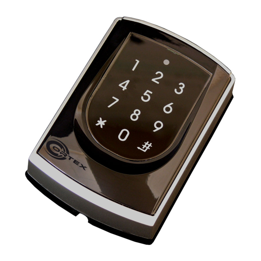
Products
A.
B.
C.
Installation
A.
2
C.
1
c.
Notice
1.Tubing:
The communication wires and power line should not be housed in the same electrical conduit or tubing.
They should always be installed in separate tubes.
2.Cable selection:
Use AWG 22-24 "Shielded twisted Pair" to avoid star wiring.
3.Power supply:
Do Not connect the reader and lock to the same power supply. While the lock activating will case the reader's power unstable and might affect the reader function.
The standard connection of power supply is the door relay and the lock use the same power supply; the reader use independent power supply.
Connector Table
P3
P2
P1
P5
P4
2
User Guide
D.
3
A.
4
B.
5
Using a screwdriver, screw the metal mounting plate C. to the wall.
Take off the plastic mounting plate B. from reader A.; and then, pull cable ends through the access
holes of C. and B. and attach B. back to reader A. .
Put on the elastic band D. embedded into the plastic frame.
Install Security Torx screw (supplied) into the hole of ACC980 at bottom with the Allen Key (supplied).
Apply power. Green and read Led will light up at the same time, and a beep sound.
P1.
Wire Application
Wire
Color
1
Blue White
Door Relay
2
Purple White
3
White
Door Sensor
4
Orange
Exit Switch
5
Purple
Alarm Output
6
Gray
7
Thick Red
Power
8
Thick Black
P2.
Wire Application
Wire
Color
1
Thin Blue
Wiegand
2
Thin Green
Pink
Beeper
3
Brown
Yellow
4
LED
5
COR-ACC980
3
Terminal Cables
P1
A.
B.
C.
B.
P3.
Description
(N.O.) DC24V1Amp
(N.C.) DC24V1Amp
(COM) DC24V1Amp
Negative Trigger Input
P4.
Negative Trigger Input
N.O. or N.C. shift by
JP1 jumper and
Shared Com with
Door Relay
DC Power 12V
DC Power 0V
P5.
Description
Wiegand DAT:1 Input
Wiegand DAT:0 Input
Beeper Output 5V
/100mA, Low
LED Green Output 5V
/20mA, Max
LED Red Output 5V
/20mA, Max
4
Allen Key and Screws
P2
P3
P4
A.
6
d.
8
D.
g.
Wire Application
Wire
Color
Networking
1
Thick Green
Module
2
Thick Blue
Contact Rating: 1A 125VAC/24VDC
Wire Application
Wire
Color
1
Red
Tamper Switch
2
Orange
3
Yellow
※After S/N: 0706-XXXXXX
(Optional)
Wire Application
Wire
Color
1
Black
3-PIN
2
White
Connector
3
Purple
V150921
7
C.
Description
RS-485(B-)
RS-485(A+)
Description
N.C.
COM
N.O.
Description
GND.
Duress
Arming
Advertisement

Related Manuals for Cortex COR-ACC980

Summary of Contents for Cortex COR-ACC980
- Page 1 COR-ACC980 V150921 Contents Products User Guide Terminal Cables Allen Key and Screws Installation Using a screwdriver, screw the metal mounting plate C. to the wall. Take off the plastic mounting plate B. from reader A.; and then, pull cable ends through the access holes of C.
- Page 2 Touch-Panel Controller + Reader Networking & Stand-alone V150921 Diagram ACC980 to ACC1000 ACC1000 WG Reader ACC980 to PC Strike Lock Magnet Lock (Bolt Lock) RS232/RS-485 or USB/RS-485 Converter N.O. N.C. Push Butto n N.O. Orange Magnetic Door Contact s N.O. N.C.
- Page 3 COR-ACC980 V150921 Relay time of lift controller setting NNN=Node ID of lift controller, TTT= relay time: 000~600=1~600 sec. M4/M8 Factory setting-2 (Function default value) M4/M6/M8 Please refer to function default value for details. Real time clock setting (Stand-Alone) YYMMDDHHmmss YYMMDDHHmmss: Year/ Month/ Day/ Hour/ Min./ Sec.
- Page 4 Touch-Panel Controller + Reader Networking & Stand-alone V150921 D.Setting up the control mode (M4/M6/M8) Access programming mode → 04 [N=4/6/8] User Auto-show Event Time Lift Anti-pass- Mode Support Access Mode 120 Holidays Duress Capacity Duty time Capacity Zone Control back 1.Card only Networking/ 3,000...