Advertisement
Quick Links
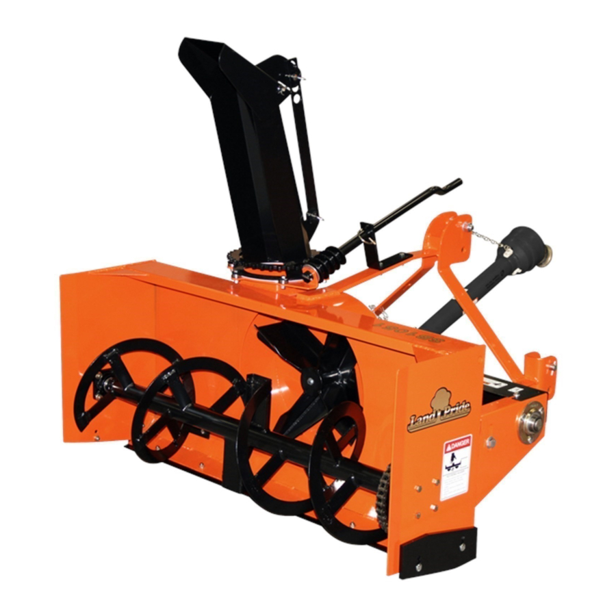
Snow Blowers
SB1051, SB1064, SB1574, & SB2584 with S/N 881640-
33234
SB10 Series Shown with Optional Hydraulic Chute Rotor and Hydraulic Chute Tilt
Table of Contents
!
Operator's Manual
Read the Operator's Manual entirely. When you see this symbol,
the subsequent instructions and warnings are serious - follow
without exception. Your life and the lives of others depend on it!
Cover illustration may show optional
equipment not supplied with standard unit.
370-027M
Printed
2/11/21
Advertisement

Related Manuals for Land Pride SB10 Series


Summary of Contents for Land Pride SB10 Series
- Page 1 Table of Contents Snow Blowers SB1051, SB1064, SB1574, & SB2584 with S/N 881640- 33234 SB10 Series Shown with Optional Hydraulic Chute Rotor and Hydraulic Chute Tilt 370-027M Operator’s Manual Read the Operator’s Manual entirely. When you see this symbol, the subsequent instructions and warnings are serious - follow without exception.
- Page 2 Land Pride assumes no responsibility for errors or omissions. Neither is any liability assumed for damages resulting from the use of the information contained herein. Land Pride reserves the right to revise and improve its products as it sees fit. This publication describes the state of this product at the time of its publication, and may not reflect the product in the future.
- Page 3 Land equipment. Download the appropriate App on your camera phone, open the App, point your phone on the QR code, and take a picture. Pride products. SB10 Series SB15 Series SB25 Series 2/11/21 SB1051, SB1064, SB1574, & SB2584 with S/N 881640- Snow Blowers 370-027M...
- Page 4 Table of Contents Important Safety Information These are common practices that may or may not be applicable to the products described in this manual. Use Safety Transport Maximum transport speed for an attached implement is 20 mph. DO Lights and Devices Machinery Safely NOT EXCEED.
- Page 5 Table of Contents Important Safety Information These are common practices that may or may not be applicable to the products described in this manual. Prepare for Emergencies Wear Avoid High Protective Equipment Pressure Fluids Hazard Be prepared if a fire starts. Keep a first aid kit and fire Wear protective clothing and Escaping fluid under pressure can...
- Page 6 Spray soapy water on the surface where the label is to all damaged or missing labels. Order new labels from your be placed. nearest Land Pride dealer. To find your nearest dealer, Peel backing from label. Press firmly onto the surface. visit our dealer locator at www.landpride.com.
- Page 7 Table of Contents Important Safety Information 33248 818-858C Warning: To Prevent Serious Injury or Death 33248 818-634C Danger: Rotating Auger 33247 818-130C Caution: To avoid Injury or Machine Damage 33248 2/11/21 SB1051, SB1064, SB1574, & SB2584 with S/N 881640- Snow Blowers 370-027M...
- Page 8 Table of Contents Important Safety Information 848-840C Danger: Hands in Chute 2-Places: On both sides of chute Available after Oct. 1, 2011 33248 818-132C Danger: Thrown Object Hazard 33248 Hydraulic Cylinder Location Hydraulic Motor Location 848-747C Warning: High Pressure Fluid Hazard Used only with hydraulic motor and hydraulic cylinders.
- Page 9 Table of Contents Introduction Introduction Land Pride welcomes you to the growing family of new Pride dealer has trained personnel, repair parts, and product owners. equipment needed to service the implement. Serial Number This Snow Blower has been designed with care and built by skilled workers using quality materials.
- Page 10 (#4) for reattachment of discharge chute (#1). SB10 Series .....18 to 32 HP SB15 Series ..... . .30-59 HP 2.
- Page 11 Table of Contents Section 2: Optional Assembly & Set-up Section 2: Optional Assembly & Set-up 33237 SB1064, SB1574, & SB2584 Chute Rotation Powered By Manual Drive Figure 2-2 33238 Chute Rotation, Manual SB1051 Chute Rotation Powered By Manual Drive Figure 2-1 For SB1064, SB1574, &...
- Page 12 Table of Contents Section 2: Optional Assembly & Set-up 33235 Chute Rotation Powered By Electric Motor Figure 2-3 Chute Rotation, Electric Motor bearing strap (#8), chute bearings (#18), lock washers (#16), and nuts (#13). Do not tighten nuts at this time. Refer to Figure 2-3: 8.
- Page 13 (#22), lock washers (#18), and nuts (#14). NOTE: Existing bearing strap (#2) is reused with SB10 Series Snow Blowers. The SB15 and SB25 Series Snow Blowers uses new bearing strap (#7). 3. Attach hydraulic mounting plate (#8) as follows: SB1051 &...
- Page 14 Table of Contents Section 2: Optional Assembly & Set-up 33245 33243 Chute Tilt Powered By Electric Actuator Chute Tilt Powered By Manual Drive Figure 2-6 Figure 2-5 Chute Tilt, Manual Refer to Figure 2-5: 1. Attach lower single hole in adjustment tilt arm (#1) to lower chute lug with adjustment pin (#2).
- Page 15 Table of Contents Section 2: Optional Assembly & Set-up Wear Bar, Lower Wear Bars, Outer Refer to Figure 2-8: Refer to Figure 2-10: 1. Attach wear bar (#1) to bottom of Snow Blower frame 1. Attach adjustable wear bars (#1) to either the upper with 3/8"-16 x 1"...
- Page 16 Snow Blower. NOTE: Land Pride’s Quick-Hitch can be attached to the tractor to provide quick and easy 3-point hook- 7. Replace wire retaining pin (#2). Make sure wire up and detachment.
- Page 17 Table of Contents Section 3: Tractor Hook-up & Unhook Driveline Installation 7. Push/pull on driveline yoke to be sure it is securely fastened to the gearbox shaft. 8. Rotate access doors (#8) closed and snap in place. DANGER 9. Pull back on driveline yoke collar and push driveline Do not engage tractor PTO while hooking-up and unhooking yoke onto the tractor PTO shaft.
- Page 18 Table of Contents Section 3: Tractor Hook-up & Unhook 24804 Outer Shielding has been removed for clarity. Driveline Maximum Extended Length Figure 3-4 23758 3. Continue with “Check Driveline Interference”. Check Driveline Interference Driveline Shortening Figure 3-3 1. Make certain driveline yokes and safety chains are 3.
- Page 19 Table of Contents Section 3: Tractor Hook-up & Unhook Hydraulic Hook-up Refer to Figure 3-6: 1. Find a suitable location to mount control box (#1) on the tractor. Usually this would be close to the DANGER operator’s right-hand side on the tractor fender or Hydraulic fluid under high pressure can penetrate skin.
- Page 20 Table of Contents Section 3: Tractor Hook-up & Unhook Unhooking Snow Blower 1. See “Long Term Storage” on page 32 before parking Snow Blower for a long period. 2. Park on a level solid surface and lower Snow Blower to ground level or onto support blocks. 3.
- Page 21 Table of Contents Section 4: Adjustments Section 4: Adjustments Hitch Pin Locations 33289 Bushing Is Located In Refer to Bottom Hitch Holes For Quick-Hitch. The lower 3-point hitch pins and upper center bolt-on bushing can be arranged in the A-frame hitch three different ways depending on user preference.
- Page 22 Table of Contents Section 4: Adjustments Chute Rotation Discharge Chute Tilting The end of the chute can be angled up or down to direct blown snow up close or far away. This is accomplished in WARNING one of three ways depending upon which option was Never rotate chute to throw snow at the tractor.
- Page 23 Table of Contents Section 4: Adjustments 33287 Outer Skid Shoe Assembly Figure 4-6 33286 Outer Skid Shoes Inner Skid Shoe Assembly Figure 4-5 Refer to Figure 4-6: Inner Skid Shoes 1. Place support blocks under Snow Blower support rests (#4) to hold unit off the ground high enough to Refer to Figure 4-5: adjust skid shoes (#1) up or down.
- Page 24 Table of Contents Section 4: Adjustments 33242 33288 Outer Wear Bar Assembly Roller Chain Take-up Adjustment Figure 4-7 Figure 4-8 Outer Wear Bars Roller Chain Take-up Refer to Figure 4-7: Refer to Figure 4-8: 1. Place support blocks under Snow Blower support IMPORTANT: Tighten roller chain until bottom chain rests to hold unit off the ground high enough to adjust has 3/8"...
- Page 25 Table of Contents Section 5: Operating Instructions Section 5: Operating Instructions Operating Checklist 5. Check for and remove foreign objects wrapped around auger and Impeller. Hazard control and accident prevention are dependent 6. Check for bent, broken, and extreme wear on auger upon the awareness, concern, prudence, and proper flighting and impeller.
- Page 26 Table of Contents Section 5: Operating Instructions Safety Information DANGER DANGER Do not lift 3-point Snow Blower fully up with driveline engaged. A Snow Blower raised too high can cause rotating Do not engage tractor PTO while hooking-up and unhooking u-joints to break apart and throw components at high speeds driveline or while someone is standing near the driveline.
- Page 27 Table of Contents Section 5: Operating Instructions WARNING WARNING Do not operate Snow Blower with loose pins, bolts, and nuts. Never pile snow where it obstructs visibility of traffic. Never Loose hardware can result in a serious breakdown causing pile snow near fire hydrants, mailboxes, water drains, shut-off bodily injury or death.
- Page 28 Table of Contents Section 5: Operating Instructions culvert edges, fire hydrants, stumps, and other IMPORTANT: Never operate Snow Blower with obstructions that are not easily seen. It really pays to chute throwing snow towards property such as inspect a new area and to develop a safe plan before vehicles and buildings that can be scratched, moving snow.
- Page 29 PTO, and begin traveling blowing snow. With a little practice you will be pleased with what you and your Land Pride Snow Blower can do. Whether you are done blowing snow, need to take a break, or just need to make a few adjustments to the Snow Blower, remember to always do the following: •...
- Page 30 Repair or replace impeller before it illegible safety labels by obtaining new labels from your causes structural damage to Snow Blower housing. Land Pride dealer. 3. Check for bent impellers (#1) that are making contact The parts on your Snow Blower have been specially...
- Page 31 A good practice would be to keep several shearbolts on hand at all times. Shearbolts can be purchased from your nearest Land Pride dealer. 1. Loosen hand knobs (#6) and remove rear drive shaft guard (#3).
- Page 32 4. Inspect drive chain for wear or have your nearest reinstallation in step 3d below. Land Pride service center inspect the drive chain. A b. Remove spacers (#3, #5, and/or #6) from used worn drive chain will accelerate sprocket wear.
- Page 33 Table of Contents Section 6: Maintenance & Lubrication 33242 Outer Wear Bar Replacement 33241 Figure 6-8 Outer Skid Shoe Replacement Figure 6-7 Outer Wear Bars (Optional) Outer Skid Shoes (Optional) Refer to Figure 6-8: Refer to Figure 6-7: Outer Wear Bar Part Numbers Outer Skid Shoe Part Numbers Part No.
- Page 34 Figure 6-9 4. Repaint parts where paint is worn or scratched to Lower Wear Bar (Optional) prevent rust. Ask your Land Pride dealer for aerosol touch-up paint. They are also available in touch-up Refer to Figure 6-9: bottles with brush, quarts, and gallon sizes by adding TU, QT, or GL to the end of the aerosol part number.
- Page 35 Table of Contents Section 6: Maintenance & Lubrication Lubrication Lubrication Multi-purpose Multi-purpose Multi-purpose Intervals in hours at which Legend spray lube grease lube oil lube lubrication is required Hours Shearbolt Sprocket Hub 1 - Zerk Type of Lubrication: Multi-purpose Grease Quantity = 2 Pumps 33249 Hours...
- Page 36 Table of Contents Section 6: Maintenance & Lubrication 33293 Required Do Not Overfill Gearbox NOTE: Do not overfill! Snow Blower should be level when checking oil. Oil expands when hot, therefore, always check oil level when cold. SB1051 & SB1064 Gearbox Remove oil level plug shown with arrow.
- Page 37 Table of Contents Section 7: Specifications & Capacities Section 7: Specifications & Capacities SB10, SB15, & SB25 Series List Specifications & Capacities Model No. Model SB1051 Model SB1064 Model SB1574 Model SB2584 Working Width 51" 64" 74" 84" Overall Width 52 3/4"...
- Page 38 Table of Contents Section 7: Specifications & Capacities SB1051 = 52 3/4" SB1064 = 65 3/4" SB1574 = 75 3/4" SB2584 = 85 3/4" SB1051 = 63 1/4" SB1064 = 63 1/4" SB1574 = 69 3/4" SB2584 = 75" SB1051 = 53 1/4" SB1064 = 53 1/4"...
- Page 39 Table of Contents Section 8: Features & Benefits Section 8: Features & Benefits SB10, SB15, & SB25 Series Features Benefits Quality Comer Gearbox Provides long life, durability construction. Greaseable bearings Less drag and extends life of unit. Quick-Hitch compatible Makes for faster and easier hook-up to tractor. Large main housing Ability to handle large drifts.
- Page 40 Table of Contents Section 9: Torque Values Chart Section 9: Torque Values Chart Torque Values Chart for Common Bolt Sizes Bolt Head Identification Bolt Head Identification 10.9 Bolt Size Bolt Size (inches) Grade 2 Grade 5 Grade 8 (Metric) Class 5.8 Class 8.8 Class 10.9 in-tpi...
- Page 41 This Warranty is limited to the repair or replacement of any defective part by Land Pride and the installation by the dealer of any such replacement part, and does not cover common wear items such as blades, belts, tines, etc. Land Pride reserves the right to inspect any equipment or parts which are claimed to have been defective in material or workmanship.
- Page 42 Corporate Office: P.O. Box 5060 Salina, Kansas 67402-5060 USA www.landpride.com...