
Related Manuals for Vulcan-Hart FC-500VC


Summary of Contents for Vulcan-Hart FC-500VC
- Page 1 USER’S MANUAL FC-500VC FC-700VC Preface Thank you for choosing a VULCAN FC-500VC. To ensure high cutting quality and optimal productivity, please read this User’s Manual thoroughly prior to use.
-
Page 2: Table Of Contents
Table of Contents NOTICE ........................4 Manual ..........................4 Cutter ..........................4 Warning labels ........................5 Safety precautions ....................6 After Turning on the Cutting Plotter ................ 9 Definitions ........................9 Chapter 1: Product Summary ................10 1.1 Machine Specifications ..................... 10 1.2 Scope of delivery ....................... - Page 3 3.7 Offline cutting from USB thumb drive ..............37 3.8 Settings ........................38 Calibrate cutter size ........................38 Offset Setting ..........................38 Operating Mode ........................... 39 System Information ........................39 Chapter 4: Troubleshooting and Maintenance ............. 40 4.1 Error information on LCD display ................40 4.2 Daily maintenance .....................
-
Page 4: Notice
NOTICE Manual • No part of this publication may be reproduced, stored in a retrieval system, or transmitted, in any form or by any means, without the prior written permission of VULCAN Corporation and Nepata Digital GmbH. • The product specifications and other information in this manual are subject to change without priornotice. -
Page 5: Warning Labels
Warning labels The following Warning Label is located on this cutting plotter. Please observe all the warnings on the label Warning: Electricity Taking care to avoid coming into contact with electricity Warning; Sharp element Taking care to avoid injury from sharp elements (e.g. needles, blades) Warning;... -
Page 6: Safety Precautions
Safety precautions Before you start operating the machine, please read this manual carefully and make sure you observe all safety precautions. The machine must only be operated by qualified adult persons. WARNING In order to avoid human injury: • During operation do not touch any moving parts like the cutting head, crossbeam or cutter holder •... - Page 7 • When cutting harder material, protect your eyes with eye protection from small particles that may fly around. • When cutting material that produces dust, always wear a protective mask • Only operate the machine, when no children are present. •...
- Page 8 CAUTION In order to avoid damage to the machine or the area around the machine • Make sure the machine is only used in the indicated operating conditions with regards to temperature and humidity • Do not use the machine in direct sunlight •...
-
Page 9: After Turning On The Cutting Plotter
After Turning on the Cutting Plotter During operations, immediately after completion of operations, and when setting the cutting plotter functions, the carriage, Y bar,will move to the origin position, and other parts which are not fixed, may move suddenly. Do not let your hands, hair, or clothing get too close to the moving parts or within their range of movement. -
Page 10: Chapter 1: Product Summary
Chapter 1: Product Summary 1.1 Machine Specifications Item FC-500VC Configuration Digital servo system, Flatbed Media hold-down method Vacuum suction Maximum cutting speed 700 mm/s (10 to 700 mm/s ) Tool 1: Max. 5.88 N (600 gf) Tool 2: Max. 5.88 N (600 Cutting pressure Approx. -
Page 11: Scope Of Delivery
1.2 Scope of delivery parts for flatbed cutting plotter 1x Power Cable 1x Ethernet cable 1x USB cable 1x blade holder 1x pen calibration tool 1x creasing tool, 1x creasing head 5 x pen 1x 30° blade 1x 60° blade 1x creasing mat parts for vacuum pump 1x transfer... - Page 12 Parts for stand 2x beams 1x left stand 1x right Beam cover stand 12xM6 hex screws 1x Philips screwdriver 1x hex kex 4x M4 philips screws...
-
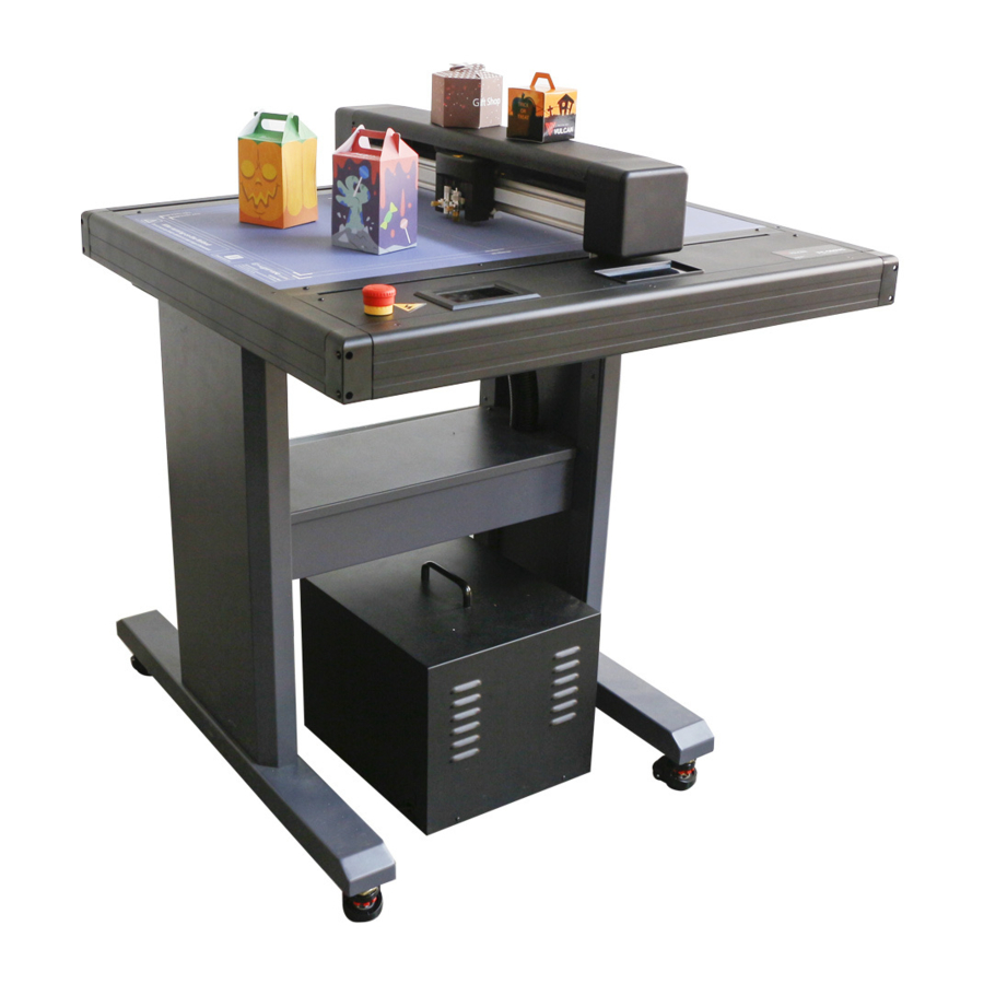
Page 13: Product Overview
1.3 Product overview pter 1: Product Summary 1. Tool carriage Part to drive the cutter/pen 2. Y Bar Holds the tool carriage; moves left/right 3.Writing panel Cutting/Plotting/Creasing work is performed on the panel 4. Storage box Placing tools such as knives, holders, pen holders, etc. - Page 14 9. Network (LAN) interface connector The connector used when connecting this cutting plotter with the network (LAN)interface cable 10. U Disk port The port that is used only for the USB memory 11. USB interface connector Used to connect the cutting plotter to the computer with a USB interface cable.
-
Page 15: Control Panel
1.4 Control Panel Screen (LCD) 1. Acceleration display Arrow key speeds for carriage control, Fast (x10) / Slow (x1 2. Carriage coordinates The coordinates of carriage on the table 3. Arrow keys To move carriage to different positions. 4. Speed Carriage moving speeds (tool1/tool2) during working. - Page 16 Vacuum To toggle of vacuum suction, ON – fast/stable hold OFF – easy replacement of next item Test cut To cut one square and one triangle for testing force of tool1/tool2. Pause To pause the cutting job when we find anything wrong. Files To choose file from USB-disk (PLT-files saved on USB-disk...
-
Page 17: Chapter 2: Installation Equipment
Chapter 2: Installation Equipment Installation Equipment 2.1 Stand and Cutter installation 1. Install beams to stand legs with the supplied hex screws 2. Install beam cover onto beams and tighten with the 4 provided Philips screws... - Page 18 3.Put machine on floor stand and tighten with 4 hex screws Please check labels on machine and stand, to ensure correct direction and positon.The feet of the machine are moveable. As shown,turn left and the wheels will be lifted,the feet are fixed. Turn right, the feet are lifted, and the wheels can move.
-
Page 19: Air Pump Installation
2.2 Air pump installation The thread of the silencer is very sharp. Wear gloves when installing to prevent injury. 1. Connect “Transfer tube” into “Air pump” and tighten it. 2. Connect “Relief valve” into “Transfer tube (on the top)” and tighten it;... - Page 20 The transfer hose need to be passed through beam cover.
-
Page 21: Use Of Tools
2.3 Use of tools To avoid injury, handle cutter blades with care. Blade Holder 1. Unscrew the blade holder cap 2. Place the blade into the slot of the blade seat 3. Close and tighten the blade holder cap to complete the installation and replacement of the blade. -
Page 22: Pen Holder
Pen holder 1. First,unscrew the Calibration tool cap,as shown. 2. First,unscrew the Calibration tool cap,as shown. 3. screw the Calibration tool cap to complete the installation and replacement of the pen. -
Page 23: Creasing Tool
Creasing tool 1. Unscrew old creasing head 2. Install new creasing heat Chapter 2: Installation Equipment... -
Page 24: Attaching A Tool
aching a tool 2.4 Attaching a tool When pushing the tool holder with your fingers, the blade tip may be protruding. Take care not to cut your fingers. When mounting the tool in the tool holder, please note the following. •... -
Page 25: Connecting To The Computer
First,Loosen the tool holder screw.Release tool cover. while pushing up the tool holder, push the tool into the holder until the flange of tool completely touches the upper part of the holder make sure that the tool bracket is engaged on the tool’s flange, and then tighten the screw. -
Page 26: Connection Via Usb Interface
Connection via USB interface Do not perform any of the following: • Do not connect or disconnect the USB cable when the computer or the plotter is performing an initialization routine. • Do not disconnect the USB cable within a 5-second period of connecting it. -
Page 27: Chapter 3: Operation
Chapter 3: Operation 3.1 Loading the Media This plotter is available with a vacuum suction flatbed • There are media that cannot be held down by vacuum suction. Please test before use. • When loading a media that cannot be securely attached using the vacuum duction, reinforce adhesion by using tape on all four sides. -
Page 28: Move The Tool Carriage
Blank media printed media – place mark below tool 1 Turn on the vacuum pump on the control panel. 3.2 Move the Tool Carriage Tool carriage can be moved manually using the POSITION key. It also can move the tool carriage to the origin, or move it certain distance to keep it away. -
Page 29: Move In Steps Manually
Move in Steps Manually When there is no file in progress, you can press the arrow keys to move the tool carriage. Tool carriage will move toward the direction of the pressed arrow key. Setting of Step Movement speed When there is no file in progress, Press the white number to modify the moving speed. -
Page 30: Move Back The Tool Carriage
Move back the Tool Carriage When the cut is over, the tool carriage will stop at a certain position, then press the “Move to origin” button to return to the original point. Press Recut to restart the same cut job. -
Page 31: Setting The Origin Point
3.3 Setting Origin Point Point where the cutting starts is called origin point. The origin point can be set at any location. Use the arrow keys to move the tool to the desired new origin point... -
Page 32: Cutting Tests
Press the “Origin” key. And the new origin has been set. The white text in the upper left corner will show the distance of the new origin point from the original origin point. 3.4 Cutting Tests Make sure that the air pump switch is turned on . This function tests the speed and force of the blade and creasing tools. -
Page 33: Test Fit
Blade holder is placed in the tool holder 1 and creasing is are plased in the tool holder 2. You can adjust the blade speed and force.Turn on the speed and pressure buttons and adjust. Click the tool 1 icon to adjust the speed and force of the tool 1. Click the tool 2 icon to adjust the speed and force of the tool 2. -
Page 34: Stop Cutting
3.7 Stop Cutting Normal Stop During the work, if you need to pause and press the “Pause” button. To continue cutting, press the “Start” again. After the work is paused. Press “Cancel”, if you want cancel the job. Emergency Stop During the work, if you encounter an emergency, you can press the emergency stop switch. -
Page 35: Recut Function
In order to reset the emergency switch: Rotate counter-clockwise to turn the switch on, then the machine will turn back on. The carriage will return to the “Original origin point” automatically. Make sure any emergency situation is fully resolved before resetting the emergency switch 3.6 Recut function Set the origin, or move the carriage directly above the first mark to determine the origin. - Page 36 After the first job, remove the media. Place the next media in the first media position. Press “Move to origin” will return to the origin and then press “Recut”,the cutter will start repeating the last job. The error of the marked position cannot exceed 1cm.
-
Page 37: Offline Cutting From Usb Thumb Drive
3.7 Offline cutting from USB thumb drive Cut jobs that were created by the application software can be saved on a USB thumb drive for direct cutting from USB. Make sure the vacuum pump is switched on before selecting the file. -
Page 38: Settings
3.8 Settings Click on the setting and the Preview box will show the meaning of the setting . Under normal circumstances, these parameters don’t need to be modified. Please refer to the following instructions If you need to adjust: Calibrate cutter size Over time, some mechanical wear may occur, resulting in reduced precision of the device. -
Page 39: Operating Mode
Operating Mode Normal: regular mode with a balance of speed and precision Precision mode: slower for high-precision jobs Hi- Speed: for larger jobs where speed is more important than precision on small cuts System Information System information will display information like: Model Machine serial number Mainboard version... -
Page 40: Chapter 4: Troubleshooting And Maintenance
Chapter 4: Troubleshooting and Maintenance 4.1 Error information on LCD display LCD Display Cause Solution Please adjust the There is not enough Change the material starting position! (X) space in X directions position and reset when working with the starting point registration marks Please adjust the There is not enough... -
Page 41: Daily Maintenance
Image does not fit There is not enough Re-adjust origin the machine size space left for this job point to leave enough space for cutting job X1 Oversize Job size is larger Restart cutter Y1 Oversize than actual working Change material X2 Oversize size of cutter position and reset... -
Page 42: Exploded Drawing
4.3 Exploded drawing... - Page 43 Parts list: Item Part Number Description FC500VC-001 Servo motor FC500VC-002 Motor belt 230 FC500VC-003 Left and right cap Carriage board FC500VC-004 FC500VC-005 Carriage FC500VC-006 Camera sensor FC500VC-007 Wheels FC500VC-008 Limit board FC500VC-009 Mainboard FC500VC-010 X cable (26) FC500VC-011 Transfer board FC500VC-012 Emergency stop switch FC500VC-013...
- Page 44 Statement of Conformity We herewith declare under sole responsibility that the under „technical data“ mentioned product meet the provisions of the following EC Directives and Harmonized Standards: EC directives: 2014/35/EC Low Voltage Directive 98/37/EC Directive on machinery (from 2009-12-29: 2006/42/EC) Standard: EN 60204-1:2006 Oliver Tiedemann Geschäftsführer...