Table of Contents
Advertisement
Advertisement
Table of Contents

Related Manuals for Cushman AC TUG


Summary of Contents for Cushman AC TUG
- Page 1 AC TUG Owner’s Guide 667907 - C ISSUED OCTOBER 2017 REVISED JULY 2018...
- Page 2 Most of the service procedures in this guide can be accomplished using common, automotive hand tools. Contact your service representative on servicing the vehicle in accordance with the Periodic Service Schedule. Repair or replacement parts are available through your TSV Cushman retailer or through TSV Service Parts Department.
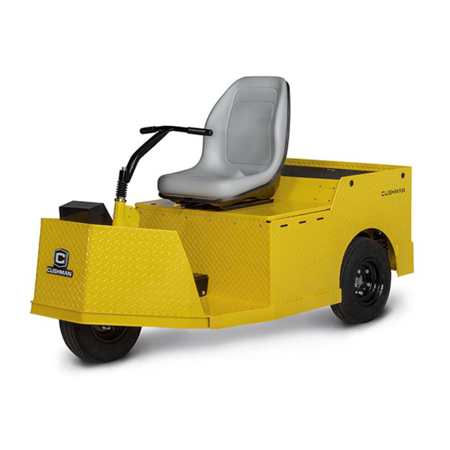
- Page 3 OWNER’S GUIDE ELECTRIC INDUSTRIAL TOW TRACTOR AC TUG STARTING MODEL YEAR 2017 Never modify the vehicle in any way that will alter the weight distribution of the vehicle, decrease its stability or increase the speed beyond the factory specifications. Such modifications can cause serious personal injury or death.
- Page 4 ELCOME This vehicle has been designed and manufactured in the United States of America (USA). The Standards and Specifications listed in the following text originate in the USA unless otherwise indicated. The use of non-Original Equipment Manufacturer (OEM) approved parts may void the warranty.
-
Page 5: Table Of Contents
ABLE OF ONTENTS SAFETY............1 GENERAL. - Page 6 ABLE OF ONTENTS REAR AXLE ..............27 BRAKES .
-
Page 7: Safety
AFETY SAFETY GENERAL For any questions on material contained in this manual, contact an authorized representative for clarification. Read all labels located on the vehicle. Always replace any damaged or missing labels. On steep hills it is possible for vehicles to coast at greater speeds. To prevent loss of vehicle control and possible seri- ous injury, speeds should be limited. -
Page 8: General Operation
CAUTIONS, WARNINGS and DANGERS contained therein. If you have any questions regarding this vehicle, contact your TSV/CUSHMAN dealer or write to the address on the back cover of this publication, Attention: Customer Care Department. - Page 9 AFETY Read the following warnings before attempting to operate the vehicle. To prevent personal injury or death, observe the following: When vehicle is to be left unattended, turn key to OFF position AND REMOVE KEY. Drive vehicle only as fast as terrain and safety considerations allow. Consider the terrain and traffic condi- tions.
-
Page 10: Maintenance
AFETY • follow all safety rules established in the area where the vehicle is being operated. • leave the vehicle when there is a risk of lightning. • reduce speed to compensate for poor terrain or conditions. • apply brake to control speed on steep grades. •... - Page 11 AFETY Keep entire body DO NOT inside vehicle WARNING drive standing Read DO NOT operate manual under influence of Tip over drugs or alcohol possibility passengers DO NOT drive on highway Secure towed loads Fuses position and size 668375 668375 To park vehicle To move forward Turn key to F...
- Page 12 AFETY...
-
Page 13: Specifications
PECIFICATIONS SPECIFICATIONS VEHICLE SPECIFICATIONS Item Specification Maximum Weight Capacity (includes weight of 650 lbs. (294.9 kg) operator, passenger, cargo, accessories) Seating Capacity 1 person Dry Weight 714 lbs. (323.9 kg) Curb Weight 1128 lbs. (711.7 kg) Overall Height 47 in. (119.38 cm) to top of seat back Overall Length 73 in. -
Page 14: Vehicle Dimensions And Incline Information
PECIFICATIONS VEHICLE DIMENSIONS AND INCLINE INFORMATION 33.5 in (85 cm) 21 in (53 cm) 1.75 in 47 in 37 in (4.4 cm) (119.38 cm) (94 cm) 52.5 in 29.5 in (133.35 cm) (74.93 cm) 34.0 in 73 in (185.42 cm) (86.36 cm) RECOMMENDED MAXIMUM RAMP GRADE RECOMMENDED MAXIMUM SIDE TILT... -
Page 15: Turning Diameter
PECIFICATIONS TURNING DIAMETER TURNING CLEARANCE DIAMETER 108 in (280 cm) (Handlebar) 55 in. INTERSECTING (140 cm) AISLE CLEARANCE 55 in (140 cm) - Page 16 PECIFICATIONS...
-
Page 17: Introduction
NTRODUCTION INTRODUCTION OPERATOR CONTROLS AND FEATURES 1. Key Switch/Direction Selector Located on the control panel, this switch enables the basic electrical system of the vehicle to be turned on and off by turning the key. This switch also permits the selection of either Forward, Reverse or Neutral/ON. - Page 18 NTRODUCTION 6. Emergency Stop Switch (included with CE option) The emergency stop switch is located on the front dash. Push down on the red knob to disconnect all electrical power to the vehi- cle motor. To restore power pull up on the red knob.
- Page 19 NTRODUCTION 12. Seat The seat can be adjusted forward or back- ward. The seat adjustment lever is located below the front edge of the of the seat bot- tom. To adjust the seat, move the lever to the left and slide the seat to the desired position.
- Page 20 NTRODUCTION...
-
Page 21: Operation
PERATION OPERATION SERIAL NUMBER LOCATION There are serial number labels in several locations on the vehicle. Design changes take place on an ongoing basis. In order to obtain correct components for the vehicle, the manufacture date code, serial number and vehicle model must be provided when ordering parts. -
Page 22: Chargers
PERATION Hydrogen gas is generated as a natural part of the lead acid battery charging process. A 4% concentration of hydrogen gas is explosive and could cause severe injury or death. Charging must take place in an area that is adequately ventilated (minimum of 5 air exchanges per hour). - Page 23 PERATION The on-board charger is located under the cargo bed panel. It is wired directly to the batteries. Before charging the batteries, park the vehicle in a well ventilated area. Turn the key switch to OFF and remove the key. Pull charger cord (P) out, plug the cord into a dedicated 15 amp AC outlet to start the charger.
-
Page 24: Operating The Vehicle
PERATION OPERATING THE VEHICLE The owner/user of the vehicle is advised to read the Safety Standard for Operator Controlled Industrial Tow Tractors ANSI/ITSDF B56.9 to define general safety practices and training needs to insure safe use of industrial tow tractors. Improper use of the vehicle or the lack of proper maintenance may result in decreased performance or dam- age to the vehicle. -
Page 25: Starting And Driving
PERATION STARTING AND DRIVING To reduce the possibility of roll-back which could result in severe injury or vehicle damage, do not release the service brake until motor has started. All vehicles are equipped with an interlock system that disables the controller and prevents the vehicle from being operated or moved while the charger is connected. -
Page 26: Transporting
PERATION TRANSPORTING This vehicle is not designed to be towed. Run-Tow Switch • The electronic parking brake is deactivated, which allows the vehicle to be towed or roll freely, except in the event of a controller failure • The service brake is still active •... -
Page 27: Maintenance
AINTENANCE MAINTENANCE VEHICLE CLEANING AND CARE Vehicle Cleaning To reduce the possibility of severe injury or vehicle damage, read and understand all instructions supplied by manufacturer of pressure washer. When pressure washing exterior of vehicle, do not use pressure in excess of 700 psi (4800 kPa). To reduce the possibility of cosmetic damage, do not use any abrasive or reactive solvents to clean plastic parts. -
Page 28: Lifting The Vehicle
AINTENANCE Some servicing operations may require the front wheel, the rear wheels, or the entire vehicle to be raised. To reduce the possibility of severe injury or death from a vehicle falling from a jack: Be sure the vehicle is on a firm and level surface. Never get under a vehicle while it is supported by a jack. -
Page 29: Tire Repair
AINTENANCE TIRE REPAIR Tool List • Lug Wrench, 3/4” • Impact Socket, 3/4” • Impact Wrench • Torque Wrench, ft. lbs. There are two different tires used on this vehicle, the standard tire is a tubeless pneumatic tire, the optional tire is a solid tire. -
Page 30: Rear Wheel Removal And Installation
AINTENANCE REAR WHEEL REMOVAL AND INSTALLATION To reduce the possibility of component damage, do not tighten lug nuts to more Tire/wheel style than 85 ft. lbs. (115 Nm) torque. may vary NOTICE: It is important to follow the cross sequence pattern when installing lug nuts. -
Page 31: Taillight/Brake Light
AINTENANCE TAILLIGHT/BRAKE LIGHT Tool List • Flat Screwdriver • Clean Cloth The taillight/brake light is an LED and does Roll Rubber Bezel Away From not have a replaceable bulb. The entire light Lens Using Small Screwdriver must be replaced. The bulb cannot be replaced in this light assembly as stated in the first paragraph. -
Page 32: Transporting Vehicle
AINTENANCE TRANSPORTING VEHICLE This vehicle is not designed to be towed. It is recommended that the vehicle be moved by placing the entire vehicle on a trailer, flat bed truck or other suitable transport. To reduce the possibility of severe injury or death while transporting the vehicle: Secure the vehicle and contents. -
Page 33: Routine Maintenance
AINTENANCE ROUTINE MAINTENANCE To prolong vehicle life, some maintenance items must be serviced more frequently on vehicles used under severe driving conditions such as extreme temperatures, extreme dust/debris conditions, or frequent use with maximum load. To access the powertrain for routine maintenance, remove the load bed. For major repair, refer to the appropriate Repair and Service Manual. -
Page 34: Brakes
AINTENANCE BRAKES To reduce the possibility of severe injury or death, always evaluate pedal travel before operating a vehicle to verify some braking function is present. Dry, Level, Clean, Paved Surface All driving brake tests must be done in a safe location with regard for the safety of all personnel. -
Page 35: Hardware
AINTENANCE HARDWARE Generally, three classes of standard hardware and two classes of metric hardware are used in the vehicle. Grade 5 hardware can be identified by the three marks on the hexagonal head and grade 8 hardware is identified by 6 marks on the head. -
Page 36: Battery Charging And Maintenance
AINTENANCE BATTERY CHARGING AND MAINTENANCE Safety NOTICE: Always observe the following warnings when working on or near batteries. To prevent battery explosion that could result in severe personal injury or death, keep all smoking materials, open flames or sparks away from the batteries. Hydrogen gas is formed when charging batteries. - Page 37 AINTENANCE Battery Maintenance Tool List • Insulated Wrench, 9/16” • Battery Carrier • Hydrometer • Battery Maintenance Kit P/N 25587-G01 • Battery Protective Spray • Torque Wrench, in. lbs • Socket, 9/16” At Each Charging Cycle To reduce the possibility of fire, never attach a battery charger to a vehicle that is to be unattended beyond the normal charging cycle.
- Page 38 AINTENANCE system. Water that is not distilled should be analyzed and, if required, filtration installed to permit the water to meet the requirements of the water purity table. Even if the water is colorless, odorless, tasteless and fit for drinking, the water should be analyzed to see that it does not exceed the impurity levels specified in the table.
- Page 39 AINTENANCE The electrolyte in a storage battery is an acid solution which can cause severe burns to the skin and eyes. Treat all electrolyte spills to the body and eyes with extended flushing with clear water. Contact a physician immediately. Any electrolyte spills should be neutralized with a solution of 2 teaspoons (10 ml) sodium bicarbonate (baking soda) dissolved in 1 quart (1 liters) of water and flushed with water.
- Page 40 AINTENANCE Battery Replacement Remove battery hold downs and cables. Lift out batteries with a commercially available lifting device. If the batteries have been cleaned and any acid in the battery rack area neutralized as recommended, no corrosion to the battery racks or surrounding area should be present. Any corrosion found should be immediately removed with a putty knife and a wire brush.
- Page 41 AINTENANCE Prolonged Storage Battery charger, controller and other electronic devices need to be disconnected since they will contribute to the premature discharge of batteries. During periods of storage, the batteries will need attention to keep them maintained and prevent discharge. In high temperatures the chemical reaction is faster, while low temperatures cause the chemical reaction to slow down.
-
Page 42: Hydrometer
AINTENANCE AC Voltage Battery charger output is directly related to the input voltage. If multiple vehicles are receiving an incomplete charge in a normally adequate time period, low AC voltage could be the cause and the power company should be consulted. Troubleshooting In general, troubleshooting will be done for two distinct reasons. - Page 43 AINTENANCE Using A Hydrometer ELECTROLYTE Draw electrolyte into the hydrometer TEMPERATURE several times to permit the thermome- °F °C ter to adjust to the electrolyte tempera- ture and note the reading. Examine the color of the electrolyte. A brown or +.032 gray coloration indicates a problem +.030...
- Page 44 AINTENANCE...
-
Page 45: Periodic Service Schedule
ERIODIC ERVICE ABLE PERIODIC SERVICE SCHEDULE C - CHECK C&A - CHECK & ADJUST CL - CLEAN R - REPLACE REMARKS Tires - check pressure and inspect condition of tires & rims Hardware - check for loose or missing Reverse Warning Indicator Overall Vehicle Condition Horn operation, Forward Motion Indicator (if equipped) Battery Pack - state of charge, condition, loose termi-... -
Page 46: Maintenance Log
ERIODIC ERVICE ABLE MAINTENANCE LOG Record periodic maintenance in the following maintenance log. MILES (KM) SERVICE PERFORMED DATE TECHNICIAN AND HOURS COMMENTS... - Page 47 ERIODIC ERVICE ABLE MILES (KM) SERVICE PERFORMED DATE TECHNICIAN AND HOURS COMMENTS...
- Page 48 ERIODIC ERVICE ABLE MILES (KM) SERVICE PERFORMED DATE TECHNICIAN AND HOURS COMMENTS...
- Page 49 ERIODIC ERVICE ABLE MILES (KM) SERVICE PERFORMED DATE TECHNICIAN AND HOURS COMMENTS...
- Page 50 ERIODIC ERVICE ABLE MILES (KM) SERVICE PERFORMED DATE TECHNICIAN AND HOURS COMMENTS...
- Page 51 ERIODIC ERVICE ABLE MILES (KM) SERVICE PERFORMED DATE TECHNICIAN AND HOURS COMMENTS...
- Page 52 ERIODIC ERVICE ABLE MILES (KM) SERVICE PERFORMED DATE TECHNICIAN AND HOURS COMMENTS...
- Page 53 ERIODIC ERVICE ABLE MILES (KM) SERVICE PERFORMED DATE TECHNICIAN AND HOURS COMMENTS...
- Page 54 ERIODIC ERVICE ABLE MILES (KM) SERVICE PERFORMED DATE TECHNICIAN AND HOURS COMMENTS...
- Page 55 ERIODIC ERVICE ABLE MILES (KM) SERVICE PERFORMED DATE TECHNICIAN AND HOURS COMMENTS...
- Page 56 ERIODIC ERVICE ABLE MILES (KM) SERVICE PERFORMED DATE TECHNICIAN AND HOURS COMMENTS...
-
Page 57: Delta Q Battery Charger
PPENDIX APPENDIX A DELTA Q BATTERY CHARGER... - Page 58 PPENDIX User’s Guide for: 912-2400, 912-3600-07, 912-4800-14 SAVE THESE IMPORTANT INFORMATIONS IMPORTANTES SAFETY INSTRUCTIONS DE SÉCURITÉ This manual contains important safety, operating, and Conserver ces instructions. Ce manuel contient des instructions installation instructions – read before using charger. importantes concernant la sécurité et le fonctionnement. Battery Safety Information Information de Sécurité...
- Page 59 PPENDIX Troubleshooting Instructions If a fault occurs, count the number of red flashes between pauses and refer to the table below: Red Flashes Cause Solution Charge Enable Fault or Check connector contacts and retry. Battery Temperature Fault Check that battery temperature is between -10°C and +50°C.
- Page 60 PPENDIX...
-
Page 61: Fault Codes
Appendix B APPENDIX B FAULT CODES... - Page 62 Appendix B TROUBLESHOOTING CHART PROGRAMMER LCD DISPLAY CODE POSSIBLE CAUSE SET / CLEAR CONDITIONS EFFECT OF FAULT Controller Overcurrent 1. External short of phase U,V, or W motor Set: Phase current exceeded the current ShutdownMotor; connections. measurement limit. ShutdownMainContactor; 2. Motor parameters are mis-tuned. Clear: Cycle KSI.
- Page 63 Appendix B TROUBLESHOOTING CHART cont’d PROGRAMMER LCD DISPLAY CODE POSSIBLE CAUSE SET / CLEAR CONDITIONS EFFECT OF FAULT Severe KSI Overvoltage 1. Incorrect (to high) battery-voltage Set: KSI voltage exceeded Severe Overvoltage limiit ShutdownMotor; applied to KSI (pin 1) Clear: Bring KSI voltage below the Severe ShutdownMainContactor;...
- Page 64 Appendix B TROUBLESHOOTING CHART cont’d PROGRAMMER LCD DISPLAY CODE POSSIBLE CAUSE SET / CLEAR CONDITIONS EFFECT OF FAULT Motor Temp Hot Cutback 1. Motor temperature is at or above the Set: Motor temperature is at or above the Temperature Hot parameter setting. Reduced drive torque.
- Page 65 Appendix B TROUBLESHOOTING CHART cont’d PROGRAMMER LCD DISPLAY CODE POSSIBLE CAUSE SET / CLEAR CONDITIONS EFFECT OF FAULT Motor Open 1. Motor phase is open. Set: Motor phase U, V, or W detected open. ShutdownMotor; 2. Bad crimps or faulty wiring. Clear: Cycle KSI.
- Page 66 OEM Set: Throttle is above "HPD Threshold" and any of Throttle activated: 1) Within 100 ms of turning Cushman Tug High Pedal Disable keyswitch "On", 2) When operator has been the following is also occurring: 1) Vehicle has been...
- Page 67 Appendix B TROUBLESHOOTING CHART cont’d PROGRAMMER LCD DISPLAY CODE POSSIBLE CAUSE SET / CLEAR CONDITIONS EFFECT OF FAULT Tow Switch Opened While Towing Set: Tow Switch (SW_4, Pin10) opens while the Tow Switch switched from "Tow" into Prevent controller from exiting Tow vehicle speed is above the parameter Zero Speed "Run"...
- Page 68 Appendix B TROUBLESHOOTING CHART cont’d PROGRAMMER LCD DISPLAY CODE POSSIBLE CAUSE SET / CLEAR CONDITIONS EFFECT OF FAULT Driver Supply 1. Internal controller fault in the voltage Set: Internal controller fault detection. ShutdownMotor; supply for the driver circuits. Clear: Cycle KSI. ShutdownMainContactor;...
- Page 69 Appendix B TROUBLESHOOTING CHART cont’d PROGRAMMER LCD DISPLAY CODE POSSIBLE CAUSE SET / CLEAR CONDITIONS EFFECT OF FAULT VCL/OS Mismatch 1. The VCL software in the controller Set: VCL and OS software do not match; when KSI ShutdownMotor; does not match the OS software in the cycles, a check is made to verify that they match ShutdownMainContactor;...
- Page 70 Appendix B...
-
Page 71: Declaration Of Conformity
PPENDIX APPENDIX C DECLARATION OF CONFORMITY... - Page 72 PPENDIX...
- Page 73 PPENDIX...
- Page 74 PPENDIX...
- Page 76 Textron Specialized Vehicles, 1451 Marvin Griffin Road, Augusta, Georgia 30906 - 3852 USA Service Parts Manuals, as well as Repair and Service Manuals are available from a local Distributor, an authorized Branch, Genuine E-Z-GO Parts & Accessories Department or at www.shopezgo.com. Copyrighted Material This manual may not be reproduced in whole or in part without the express permission of...