
Related Manuals for Asus AAEON UP Xtreme i11


Summary of Contents for Asus AAEON UP Xtreme i11
- Page 1 UP Xtreme i11 Maker Board UPX-TGL01 User’s Manual 1 Edition Last Updated: June 15, 2021...
- Page 2 Copyright Notice This document is copyrighted, 2021. All rights are reserved. The original manufacturer reserves the right to make improvements to the products described in this manual at any time without notice. No part of this manual may be reproduced, copied, translated, or transmitted in any form or by any means without the prior written permission of the original manufacturer.
- Page 3 Acknowledgements All other product names or trademarks are properties of their respective owners. Microsoft Windows and Windows 10 are registered trademarks of Microsoft ⚫ Corp. Intel® and Celeron® are registered trademarks of Intel Corporation ⚫ Intel Core™ is a registered trademark of Intel Corporation ⚫...
- Page 4 Packing List Before setting up your product, please make sure the following items have been shipped: Item Quantity UPX-TGL01 If any of these items are missing or damaged, please contact your distributor or sales representative immediately. Preface...
- Page 5 About this Document This User’s Manual contains all the essential information, such as detailed descriptions, and explanations on the product’s hardware and software features (if any), its specifications, dimensions, jumper/connector settings and definitions, and driver installation instructions (if any) to facilitate users in setting up their product Users may refer to the product page at AAEON.com for the latest version of this document.
- Page 6 Safety Precautions Please read the following safety instructions carefully. It is advised to keep a printed copy of this manual in an easy to access location for reference. All cautions and warnings on the device should be noted. Make sure the power source matches the power rating of the device. Position the power cord so that people cannot step on it.
- Page 7 If any of the following situations arises, please the contact our service personnel: Damaged power cord or plug Liquid intrusion to the device iii. Exposure to moisture Device is not working as expected or in a manner as described in this manual The device is dropped or damaged Any obvious signs of damage displayed on the device...
- Page 8 FCC Statement This device complies with Part 15 FCC Rules. Operation is subject to the following two conditions: (1) this device may not cause harmful interference, and (2) this device must accept any interference received including interference that may cause undesired operation.
- Page 9 China RoHS Requirements (CN) 产品中有毒有害物质或元素名称及含量 AAEON System QO4-381 Rev.A0 有毒有害物质或元素 部件名称 铅 汞 镉 六价铬 多溴联 多溴二苯 苯(PBB) 醚(PBDE) (Pb) (Hg) (Cd) (Cr(VI)) 印刷电路板 × ○ ○ ○ ○ ○ 及其电子组件 外部信号 × ○ ○ ○ ○ ○ 连接器及线材 外壳 ○...
- Page 10 China RoHS Requirement (EN) Hazardous and Toxic Materials List AAEON System QO4-381 Rev.A0 Hazardous or Toxic Materials or Elements Component Name PCB and Components Wires & Connectors for Ext.Connections Chassis CPU & RAM HDD Drive LCD Module Optical Drive Touch Control Module Battery This form is prepared in compliance with the provisions of SJ/T 11364.
-
Page 11: Table Of Contents
Table of Contents Chapter 1 - Product Specifications ..................1 Specifications ........................2 Chapter 2 – Hardware Information ..................4 Dimensions ........................5 Jumpers and Connectors ....................6 List of Jumpers and Connectors .................. 8 2.3.1 Power Button (SW1) ..................... 9 2.3.2 RTC (CN1) ....................... - Page 12 2.3.23 Audio Jack (CN33) ..................... 28 2.3.24 Fan Connector (J1) ..................... 28 2.3.25 AT/ATX Mode Jumper (JP1) ................29 Chapter 3 – Software Installation ..................30 Linux Setup ........................31 Windows Drivers Installation ..................31 Dummy Driver Installation ................... 31 Appendix A –...
-
Page 13: Chapter 1 - Product Specifications
Chapter 1 Chapter 1 - Product Specifications... -
Page 14: Specifications
Specifications System Processor 11th Gen Intel® Core™ Processor SoC Core i7-1185GRE Core i5-1145GRE Core i3-1115GRE Celeron® 6305E Graphics Intel® Iris® Xe Graphics RJ45 Ethernet Connector x 2 HDMI/DP Stack Connector x 1 Power Button / LED x 1 DC Connector (Lockable) x 1 10-pin USB 2.0 x 2 / HSUART x 1 SATA Connector with Power Connector (5V, GND) x 1... - Page 15 System RTC battery, CR2032 x 1 Power Dimension 120.35 x 122.5 mm Memory DDR4 SO-DIMM Slot x 2 (up to 64GB 3200Mhz) Storage SATA III (6.0Gbps) x 1: a - SATA Connector x1 b - M.2 2280 M Key NVMe (PCIe [x2]) x 1 Display Interface HDMI 2.0 x 1 DP 1.4 x 1 + eDP x 1, 4K at 60hz internal...
-
Page 16: Chapter 2 - Hardware Information
Chapter 2 Chapter 2 – Hardware Information... -
Page 17: Dimensions
Dimensions Chapter 2 – Hardware Information... -
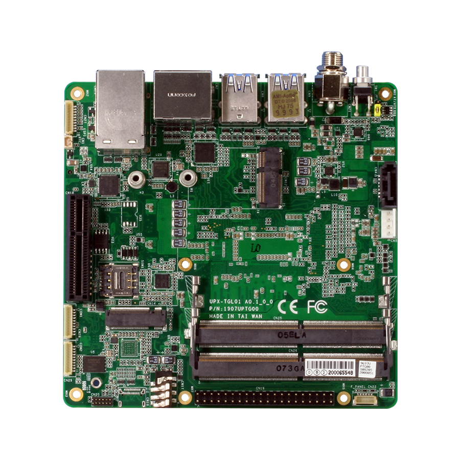
Page 18: Jumpers And Connectors
Jumpers and Connectors Top: Chapter 2 – Hardware Information... - Page 19 Bottom: Chapter 2 – Hardware Information...
-
Page 20: List Of Jumpers And Connectors
List of Jumpers and Connectors Please refer to the table below for all of the board’s jumpers and connectors that you can configure for your application Label Function Power Button HDMI/DP Dual Port SATA Connector USB Type A Dual Port USB Type A Dual Port CN10 USB Type C... -
Page 21: Power Button (Sw1)
2.3.1 Power Button (SW1) Signal Signal PWR_SW# PWR_SW# SW1_LED_P SW1_LED_N 2.3.2 RTC (CN1) Signal RTC_VCC Chapter 2 – Hardware Information... -
Page 22: Hdmi/ Dp Dual Port (Cn2)
2.3.3 HDMI/ DP Dual Port (CN2) Signal Signal DP_TXP0 DP_TXN0 DP_TXP1 DP_TXN1 DP_TXP2 DP_TXN2 DP_CLK+ DP_CLK- CONFIG1 CONFIG2 DP_AUX_P DP_AUX_N DP_HPD 3.3V HDMI_TXP0 HDMI_TXN0 HDMI_TXP1 HDMI_TXN1 HDMI_TXP2 HDMI_TXN2 HDMI_CLK+ HDMI_CLK- HDMI_CEC DDC_CLK DDC_DATA HDMI_HPD Chapter 2 – Hardware Information... -
Page 23: Edp (Cn3)
2.3.4 eDP (CN3) Signal Signal +VDD_3V3 +VDD_3V3 EDP_TXN2 EDP_TXP2 EDP_TXN1 EDP_TXP1 EDP_TXN0 EDP_TXP0 EDP_TXN3 EDP_TXP3 EDP_AUXN EDP_AUXP BKLT_CTRL BKLT_EN EDP_HPD +12V +12V +12V +12V Chapter 2 – Hardware Information... -
Page 24: Sata Connector (Cn4)
2.3.5 SATA Connector (CN4) Signal Signal SATA_TXP0_C SATA_TXN0 SATA_RXN0 SATA_RXP0 2.3.6 USB Type A Dual Port (CN8) Signal Signal USB2_D1- USB2_D1+ USB3_RX1- USB3_RX1+ USB3_TX1- USB3_TX1+ USB2_D2- USB2_D2+ Chapter 2 – Hardware Information... -
Page 25: Usb Type A Dual Port (Cn9)
2.3.7 USB Type A Dual Port (CN9) Signal Signal USB2_D3- USB2_D3+ USB3_RX3- USB3_RX3+ USB3_TX3- USB3_TX3+ USB2_D4- USB2_D4+ USB3_RX4- USB3_RX4+ USB3_TX4- USB3_TX4+ Chapter 2 – Hardware Information... -
Page 26: Usb Type C (Cn10)
2.3.8 USB Type C (CN10) Signal Signal SSTXP1 SSTXN1 SBU1 SSRXN2 SSRXP2 SSTXP2 SSTXN2 SBU2 SSRXN1 SSRXP1 Chapter 2 – Hardware Information... -
Page 27: Usb 2.0/Uart 1X10P Wafer (Cn11)
2.3.9 USB 2.0/UART 1x10P Wafer (CN11) Signal Signal USB2_D5- USB2_D5+ USB2_D6- USB2_D6+ UART_RX UART_TX 2.3.10 M.2 2230 E Key Slot (CN12) Signal Signal +3.3V USB2_D10+ +3.3V USB2_D10- CNV_WR_LANE1_DN CNV_RF_RST# CNV_WR_LANE1_DP CNV_CLKREQ_R CNV_WR_LANE0_DN Chapter 2 – Hardware Information... - Page 28 Signal Signal CNV_WR_LANE0_DP CNV_WR_CLK_DN CNV_RGI_RSP_R CNV_WR_CLK_DP CNV_RGI_DT CNV_RGI_RSP PCIE9_TXP CNV_BRI_DT PCIE9_TXN PCIE9_RXP PCIE9_RXN PCIE5_CLKP PCIE9_CLKN SUS_CLK WIFI_RST# PCIE_CLKREQ# BT_EN PCIE_WAKE# WIFI_EN CNV_WT_LANE1_DN CNV_WT_LANE1_DP CNV_WT_LANE0_DN CNV_WT_LANE0_DP Chapter 2 – Hardware Information...
-
Page 29: 2280 M Key Slot (Cn13)
Signal Signal CNV_WT_CLK_DN +3.3V CNV_WT_CLK_DP +3.3V 2.3.11 M.2 2280 M Key Slot (CN13) Signal Signal +3.3V +3.3V +3.3V +3.3V +3.3V +3.3V PCIE1_RXN PCIE1_RXP Chapter 2 – Hardware Information... - Page 30 Signal Signal PCIE1_TXN PCIE1_TXP SSD_DEV_SLP SMB_CLK_1V8 PCIE0_RXN SMB_DATA_1V8 PCIE0_RXP PCIE0_TXN PCIE0_TXP PLT_RST# PCIE_CLKREQ# PCIE3_CLKN PCIE_WAKE# PCIE3_CLKP +3.3V +3.3V +3.3V Chapter 2 – Hardware Information...
-
Page 31: 3052 B Key Slot (Cn14)
2.3.12 M.2 3052 B Key Slot (CN14) Signal Signal +3.3V +3.3V FULL_CARD_POWER_OFF# USB2_D8+ W_DISABLE#1 USB2_D8- USB3_RX- UIM_RST USB3_RX+ UIM_CLK UIM_DAT USB3_PX- UIM_PWR USB3_PX+ PCIE10_RXN Chapter 2 – Hardware Information... - Page 32 Signal Signal PCIE10_RXP PCIE10_TXN PCIE10_TXP PLT_RST#(3.3V) PCIE_CLKREQ# PCIE4_CLKN PCIE_WAKE# PCIE4_CLKP PLT_RST#(1.8V) +3.3V +3.3V +3.3V Chapter 2 – Hardware Information...
-
Page 33: Lan Dual Port (Cn15)
2.3.13 LAN Dual Port (CN15) Signal Signal LAN1_MDI0+ LAN1_MDI0- LAN1_MDI1+ LAN1_MDI1- LAN1_MDI2+ LAN1_MDI2- LAN1_MDI3+ LAN1_MDI3- R10A LAN1_ACTLED- LAN1_ACTLED+ LAN1_LINK1000# LAN1_LINK100# LAN2_MDI0+ LAN2_MDI0- LAN2_MDI1+ LAN2_MDI1- LAN2_MDI2+ LAN2_MDI2- LAN2_MDI3+ LAN2_MDI3- R10B LAN2_ACTLED- LAN2_ACTLED+ LAN2_LINK1000# LAN2_LINK100# Chapter 2 – Hardware Information... -
Page 34: Pci Express Slot (Cn18)
2.3.14 PCI Express Slot (CN18) Signal Signal +12V +12V +3.3V +3.3V PLT_RST# PCIE0_CLKP PCIE0_CLKN PCIE4_P0_RXP PCIE4_P0_RXN PCIE4_P1_RXP PCIE4_P1_RXN PCIE4_P2_RXP PCIE4_P2_RXN PCIE4_P3_RXP PCIE4_P3_RXN +12V +12V +12V SMB_CLK SMB_DATA +3.3V +V3.3A PCIE_WAKE# Chapter 2 – Hardware Information... -
Page 35: 40-Pin Hat Connector (Cn19)
Signal Signal PCIE4_P0_TXP PCIE4_P0_TXN PCIE4_P1_TXP PCIE4_P1_TXN PCIE4_P2_TXP PCIE4_P2_TXN PCIE4_P3_TXP PCIE4_P3_TXN 2.3.15 40-Pin HAT Connector (CN19) Signal Signal +3.3V I2C1_DAT/ GPIO1 I2C1_CLK/ GPIO2 ANALOG_DATA / GPIO3 UART_TX/ GPIO16 UART_RX/ GPIO17 GPIO4 I2S_BCLK/ GPIO18 GPIO5 GPIO6 GPIO19 +3.3V GPIO20 SPI_MOSI/ GPIO7 Chapter 2 – Hardware Information... -
Page 36: Cpld And Bios Update (Cn20)
Signal Signal SPI_MISO/ GPIO8 GPIO21 SPI_CLK/ GPIO9 SPI_CS0/ GPIO22 SPI_CS1/ GPIO23 I2C0_DAT/ GPIO10 I2C0_CLK/ GPIO24 GPIO11 GPIO12 PWM0/ GPIO25 PWM1/ GPIO13 I2S_SYNC/ GPIO14 GPIO26 GPIO15 I2S_SDI/ GPIO27 I2S_SDO/ GPIO28 2.3.16 CPLD and BIOS Update (CN20) Signal Signal JTAG_TCK JTAG_TDO 1.8V JTAG_TMS SPI_CS SPI_CLK... -
Page 37: Dc Jack (Cn21)
2.3.17 DC Jack (CN21) Signal DC_IN 2.3.18 Front Panel (CN22) Signal Signal RESET POWER S/W +3.3V Chapter 2 – Hardware Information... -
Page 38: Dc Terminal Block (Cn23)
2.3.19 DC Terminal Block (CN23) Signal DC_IN 2.3.20 RS232/ 422/ 485 1x10P Wafer (CN28/CN29) Signal Signal DCD/ RS422TX-/ S485- RX/ RS422TX+/ RS485+ TX/ RS422RX+ DTR/ RS422RX- Chapter 2 – Hardware Information... -
Page 39: Atx Power (Cn31)
2.3.21 ATX Power (CN31) Signal Signal 12V OUT 12V OUT 2.3.22 SATA Power (CN32) Signal Chapter 2 – Hardware Information... -
Page 40: Audio Jack (Cn33)
2.3.23 Audio Jack (CN33) Signal Signal MIC_LR LOUT_R AUDIO-JD LOUT_L 2.3.24 Fan Connector (J1) Signal Signal TACH Chapter 2 – Hardware Information... -
Page 41: At/Atx Mode Jumper (Jp1)
2.3.25 AT/ATX Mode Jumper (JP1) Signal ATX_MODE PWRBTN AT_MODE ATX Mode (Default) AT Mode Chapter 2 – Hardware Information... -
Page 42: Chapter 3 - Software Installation
Chapter 3 Chapter 3 – Software Installation... -
Page 43: Linux Setup
Linux Setup UP Xtreme i11 supports Linux operating systems (see Chapter 1 for specifications). For instructions on how to install a Linux OS onto your UP Xtreme i11, you can find several guides and tutorials in the wiki section of the UP Board website at https://up- board.org for both installing supported distributions as well as porting your own Linux... - Page 44 Step 2 – Under “Other devices” look for Intel High Definition Audio. Right click on the device and select “Update driver”. Step 3 – Select “Browse my computer for drivers” Chapter 3 – Software Installation...
- Page 45 Step 4 – Click “Browse…” and select the folder where you saved the dummy driver software. Chapter 3 – Software Installation...
- Page 46 Step 5 – Repeat for Unknown device Chapter 3 – Software Installation...
-
Page 47: Appendix A - Up Framework Sdk Installation
Appendix A Appendix A – UP Framework SDK Installation... -
Page 48: Introduction
Introduction This section provides instructions for the installation of the UP Framework SDK. Instructions are provided for Windows 10 and Windows IoT Core. You can download the latest version of UP Framework SDK from the UP community: https://downloads.up-community.org/download/up-sdk-for-windows-10-and-windows-iot/ Installation for Windows 10 Step 1 Locate the downloaded file UpFrameworkSetup.msi and run the installer. - Page 49 Step 2 Select the installation folder. Default destination path is C:\Program Files(x86)\AAEON\ You may also choose to install the UP Framework SDK for all users or only the current user. Press “Next” to continue installation. Step 3 Press “Next” to confirm the installation. Appendix A –...
- Page 50 Step 4 Press “Close” to exit once setup is complete. Appendix A – UP Framework SDK Installation...
-
Page 51: Installation For Windows Iot Core
Installation for Windows IoT Core Before you begin, make sure you have downloaded and installed the latest version of the Windows IoT Core image from the UP community. Installation requires using a connected PC with the UP Framework SDK software downloaded and saved. - Page 52 Step 2 Download the UP Framework SDK to your PC and unzip the files. Open PowerShell as an Administrator. Enter the command RemoteInstallation.ps1 to install the UP Framework SDK. Enter the IP address of the UP IoT Core device when prompted. Appendix A –...
-
Page 53: Appendix B - Cables And Connectors
Appendix B Appendix B – Cables and Connectors... -
Page 54: Cables And Connectors
Cables and Connectors This table provides detailed information about the cables and connectors used by the UP Xtreme i11 (UPX-TGL01). If you have any questions about the configuration of your board, please contact your AAEON sales representative. Mating Mating Cable Label Connector PN Description... - Page 55 Mating Mating Cable Label Connector PN Description Cable PN Description DC Power Jack.3P (DC CN21 165250320K 12V) Wafer Box.6P. Front CN22 1655906033 Panel (Power on + Reset) COM Port.9P.COM Wafer Box.10P. COM Cable to CN28 1655901000 170X000255 port VGA.210mm.FLYINGW AY.FWAA-1375. COM Port.9P.COM Wafer Box.10P.